1
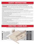
~MLCS USER’S MANUAL~ Cast Iron Router Table Extension For #2391, #2396, #2397 + #9769 We appreciate your purchase. This table can be mounted easily to a table saw, cabinet, or open steel stand. If you wish to mount this table to the right of your saw blade, not directly to the table saw’s table, a T-square type rip fence with heavy steel rails will be needed to support the table. Support legs will also be required. You can make your own or modify existing legs. WARNING: Please read this manual fully and be sure you understand its instructions prior to operating or assembling this tool. Inspect for damage and missing parts upon receipt. Please contact MLCS Woodworking with any problems or questions. Copyright 2009 MLCS 1 PARTS LIST & CONTENTS Part no. Description Quantity 1 2 3 4 5 6 7 Cast Iron Router Table L-Aluminum Router Table Fence Laminated MDF Fence Faces Dust Port Dust Port Adaptor Bit Guard Aluminum Miter T-Track Owner's Manual 1 1 2 1 1 1 1 1 Hardware (see Hardware Parts list--next page) Copyright 2009 MLCS 2 HARDWARE PARTS LIST Part # Name Specification Quantity H1 H2 H3 H4 H5 H6 H7 H8 H9 H10 H11 H12 H13 H14 H15 H16 H17 Hex Head Bolt Hex Head Bolt Hex Head Bolt Hex Head Bolt Flat Washer Flat Washer Flat Washer Locking Washer Square Washer Hex Nut Hex Nut J-Screw Hooks Machine Screw Machine Screw Self Tapping Flat Head Screw Threaded Through Knobs Threaded Through Knobs M10 x 1.5 x 1-1/2” M8 x 1.25 x 1-1/2” M8 x 1.25 x 1” M6 x 1.0 x 1” 10mm 8mm 6mm 8mm 32mm x 25mm M8 x 1.25 M6 x 1.0 M6 x 1.0 M6 x 1.0 x 5/8” M5 x 0.8 x 2” #4 x 1/2” M8 x 1.25 M6 x 1.0 6 4 6 2 8 6 2 4 4 4 2 2 3 2 12 6 2 RECOMMENDED ACCESSORIES Router Speed Control (MLCS Item #9400 or #9410) Featherboards (MLCS Item #9478) Push Sticks and Blocks (MLCS Set #9167 or #9169) Copyright 2009 MLCS 3 IMPORTANT GENERAL SAFETY TIPS NOTE: Please read entire manual before using your Table. Application –specific safety information is included throughout this manual! This manual is not intended as a general instruction guide for woodworking or use of power tools. Appropriate guidance and training should be sought from other sources and use of this product should not be attempted without appropriate background knowledge. 1) Do not stand or sit on your new router table. 2) Properly secure and level your table and base prior to each use. 3) Work area should always be clean, dry, and well-lit. 4) For safety, always use bit guard, dust collection and a router table fence or starting pin. 5) Use a variable speed router or router speed control to reduce the speeds when cutting large diameter bits, as follows: 1/4" to 2" D bits: 18,000 RPM; 2-1/8" to 2-1/2" D bits: 16,000 RPM; 2-5/8" to 3-1/2" D Bits: 12,000 RPM. Bits with a carbide height greater than 1-1/2" should also be run at 16,000 RPM or less and it is EXTREMELY important to make multiple passes with these router bits. 6) Always choose an appropriate tool for the job. Forcing a tool to due a job for which it was not designed can cause damage and injury. 7) Featherboards, clamps, and vises should be used to secure your work when needed. 8) Wear appropriate protective gear, including face shield, dust mask, ear protection and safety glasses. Standard eyeglasses do NOT provide appropriate protection in the workshop environment. 9) Gloves, jewelry, and loose clothing should not be worn when operating power tools, as they can become caught in the machine, causing serious injury. Long hair should also be tied back. 10) Always keep your tools and accessories in good repair. Inspect frequently for signs of wear, misalignment, breakage, weakened mountings, and other potential operating issues. Damaged parts should be promptly repaired or replaced. 11) Always disconnect the power before moving, repairing or performing maintenance on machinery. 12) Never allow those who may disregard safety into the work area, especially children and pets. 13) Never reach too far. Always maintain your balance and footing when working with power tools. 14) Pay careful attention to your environment and always use good judgment. Copyright 2009 MLCS 4 ASSEMBLY INSTRUCTIONS (These instructions are intended ONLY when directly mounting your table to a cast iron table saw. A minimum 27” table depth is required for proper mounting. If your table is deeper than 27”, you will need shims (not included) to fill the extra space.) 1) Detach your table saw’s left extension wing. 2) Install your router table using the included hardware. NOTE: Do not use the factory bolts from your table saw, as they may not be the proper length or grade. If the provided bolts are not the proper size for your table saw, you should obtain your own Grade 5 bolts. 3) Determine if your saw uses a 3 or 4 bolt pattern. Tip: Craftsman and Ridgid saws use four bolts. Most other brands of saws use 3. a) Four Hole Mounting: Typically, 5/16” bolts are used with a 4-hole mounting system. In the (2) middle holes, use the heavy rectangle washers. Each bolt should be installed with (2) 10mm flat washers, (1) lock washer and (1) nut. Some Ridgid models may have tapped rather than through holes. If your table saw requires bolts other than 5/16”-18 TPI, you will need to obtain Grade 5 bolts on your own. b) Three Hole Mounting: Always use the heavy rectangle washers on each bolt. Delta table saws use 7/16”-20 TPI x 1-1/2” hex bolts (not included), while most other imported models use M10 x 1.5 x 40 mm hex bolts. If your table saw requires a different size, you will need to obtain Grade 5 bolts on your own. 4) Lift the router table into place. This is a 2-person operation! Snug the bolts while someone secures the table in position. Both surfaces should be smooth and flat before attempting this step. 5) Secure the router table. Tighten the bolts into place slowly and evenly. A soft-tipped mallet can be used to gently tap the table surfaces. Paper or brass shims may be needed if the (2) tables’ edges are not flat. 6) Install the miter t- track with the (3) M6 x 1.0 x 5/8” flat head machine screws. 7) Install the dust port. Use M4 x 8mm screws to lock the dust port in position. Use the (2) M5 x 0.8 x 2” round head machine screws to attach the dust port to the L-Aluminum fence. Miter Gauge Track Installation (see step 6) Copyright 2009 MLCS 5 8) Attach the (2) MDF sub-fences to the L-Aluminum fence with (4) M6 x 1.0 x 1” hex bolts using the t-tracks in the back face of the MDF fence face. 9) Attach the L-Aluminum fence to the cast iron table with (2) M8 x 1.25 x 1” hex bolts, (2) M8 flat washers and (2) 3/8” T-Knobs. 10) Pre-assemble the bit guard with (2) M6 x 1.25 x 1” hex bolts and (2) M6 x 1.25 through knobs. Both bolt heads then slide into the T-Track in the MDF router fence to attach the bit guard. 11) Mount your router to the MLCS All-in-One Router Plate #9338 or MLCS Aluminum Router Plate #9334. For most common routers, the MLCS Aluminum Plate #9334 is pre-marked. The All-in-One Router Plate Kit #9338 is not marked. For either plate, you will need to drill holes to mount your router. Bit Guard Installation (see step 10) 12) Insert your router and plate into the router tabletop. You may need to make the plate flush by adjusting the (4) Allen head leveling screws in the corners of the plate. 13) Screw the fence hang hooks into the table about 3/8”. Then use a 10mm wrench to tighten the M6 x 1.25 hex jam nuts. 14) When not in use, you should hang the fence on the (2) J-hooks. Fence Hang Hooks (see step 13 TIPS FOR PROPER OPERATION 1) File Sharp Edges. If your table saw has a bevel on the leading edge, you may wish to file your router table to match. 2) Dust Collection. Dust collection is essential when operating your router table. The port on your table accepts a 2-1/2” fitting as used on most Shop Vacs. To ensure proper air flow over the router motor and to properly remove the most dust and chips, a hose of 2-1/2” or larger is strongly recommended. You may need an adapter (not included) for a hose larger or smaller than the standard 2-1/2”. Copyright 2009 MLCS 6 3) Miter Gauge Usage. The miter gauge slot is for use with a miter gauge and is compatible with standard 3/8” x 3/4” miter bars, with or without the T-bar. (Miter Gauge not included.) If you wish to adjust the fence perpendicular to the miter gauge, you should position the miter gauge at 90-degrees and place it into the slot. Loosen the T-knobs and use a square to align it to the fence. 4) Feed Direction. The workpiece should always be fed AGAINST the cutter rotation (see picture). Feeding the workpiece with the cutter direction is called “climb-cutting” and is extremely dangerous, as the cutter will pull the workpiece out of your grasp. Be sure you fully understand bit rotation and feed direction prior to operating your router in this table. If you need assistance, ask a router retailer, call and speak to one of our woodworkers, or refer to a Guide Book for router usage. REMEMBER--NEVER CLIMB CUT! 5) Adjusting the Subfences. Each MDF subfence can move along the main fence about 2”, allowing an opening for your router bit from 0” to 4”. KNOBS. MLCS THREE-YEAR WARRANTY AND SATISFACTION GUARANTEE MLCS is dedicated to ensuring the quality and durability of every product we sell. We guarantee to the purchaser that this product is free of defects in materials and workmanship for 3 years. Guarantee is limited to repair, replacement, or refund at MLCS’s discretion and does not cover any coincidental loss, economic or otherwise. Warranty Terms and Conditions: Please contact MLCS within 30 days of discovering a problem. Defects caused by misuse, abuse, negligence, accidents, or after-purchase alterations will not be covered. Using this item for other than its intended purpose will void the warranty. Warranty Procedure: Defective product must be returned to MLCS before a refund or replacement can be processed. Please contact us at 1-800-533-9298 to have a return label sent to you. Upon inspection of the returned product, we will repair and return the product, replace it, or issue a credit at our discretion. If the product is found not to be defective, a nominal 10% restocking fee will be deducted from any credit to cover costs of shipping, checking, and repackaging the product. Copyright 2009 MLCS 7