1
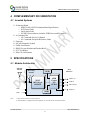
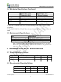
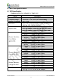
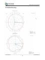
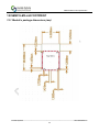
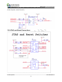
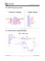
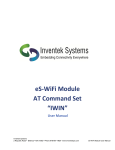
Inventek Systems ISM4319-M3X-L44-X Embedded Serial-to-Wi-Fi Module eS-WiFi 802.11 b/g/n Data Sheet TM _____________________________________________________________________________________________ Inventek Systems - www.Inventeksys.com 2 Republic Road • Billerica, MA 01862 • Phone 978-667-1962 Product Specification 1 ISM4319-M3X Product Specification ISM4319-M3X Product Specification Table of Contents 1 2 GENERAL DESCRIPTION ................................................................................................... 4 PART NUMBER DETAIL DESCRIPTION .......................................................................... 5 2.1 Ordering Information ...................................................................................................... 5 3 GENERAL FEATURES ......................................................................................................... 5 3.1 Limitations ...................................................................................................................... 6 3.2 Regulatory Compliance .................................................................................................. 6 3.3 FCC User’s Manual Statements: ..................................................................................... 7 3.4 Industry Canada User’s Manual Statements: .................................................................. 8 4 COMPLEMENTARY DOCUMENTATION ........................................................................ 9 4.1 Inventek Systems ............................................................................................................ 9 5 SPECIFICATIONS ................................................................................................................. 9 5.1 Module Architecture ....................................................................................................... 9 5.2 External Antenna Connections ..................................................................................... 10 5.3 Mechanical Specifications (Keep out) .......................................................................... 10 5.4 Mechanical Specifications (Continued) ........................................................................ 11 5.5 Environmental Specifications ....................................................................................... 11 6 HARDWARE ELECTRICAL SPECIFICATIONS ............................................................. 11 6.1 Absolute Maximum Ratings ......................................................................................... 11 6.2 Recommended Operating Ratings ................................................................................ 11 6.3 Power Consumption ...................................................................................................... 12 6.3.1 Estimate Power Consumption ................................................................................... 12 6.3.2 Stop Mode ................................................................................................................. 12 7 Pin out ................................................................................................................................... 13 7.1.1 Detailed Pin Description ........................................................................................... 14 7.1.2 Configuration Pins: ................................................................................................... 15 *Requires a 10K ohm pull down .................................................................................................. 15 8 AC CHARACTERISTICS ................................................................................................... 15 8.1 UART ............................................................................................................................ 15 8.1.1 Data Mode ................................................................................................................. 15 8.1.2 2.1.2 Flow Control .................................................................................................... 15 8.1.3 2.1.3 Supported Baud Rates ...................................................................................... 16 8.1.4 Default Serial Configuration ..................................................................................... 16 8.2 2.2 USB (Universal Serial Bus) .................................................................................... 16 8.3 2.3 SPI (Serial Peripheral Interface Bus) ...................................................................... 16 8.4 USB ............................................................................................................................... 16 8.5 GPIO ............................................................................................................................. 16 _____________________________________________________________________________________________ Inventek Systems DOC-DS-20023-4.0 2 ISM4319-M3X Product Specification 8.6 ADC’s ........................................................................................................................... 16 9 Wi-Fi RF Specification ......................................................................................................... 17 9.1 RF Specification............................................................................................................ 17 9.2 RF Specification (Continued) ....................................................................................... 18 10 Antenna Patterns ................................................................................................................... 18 10.1 External Antenna .......................................................................................................... 18 10.2 PCB Etch antenna gain on the evaluation board ........................................................... 19 10.3 Farfield Directivity........................................................................................................ 20 11 On Board Processor .............................................................................................................. 21 12 ISM4319-M3-L44 FOOTPRINT .......................................................................................... 22 12.1 Module’s package dimensions (mm) ............................................................................ 22 13 Typical Application Circuit .................................................................................................. 23 13.1 Reference Schematic (EVB) ......................................................................................... 24 13.2 USB to UART ............................................................................................................... 25 13.3 Connecting Microcontroller to eS-WiFi UART ........................................................... 26 13.4 EXTERNAL FLASH FOR OVER THE AIR UPGRADE........................................... 27 13.5 JTAG and Reset Connections ....................................................................................... 27 13.6 eS-WiFi Programming Options .................................................................................... 28 13.7 eS-WiFi USB Direct Connection Option ...................................................................... 28 14 Product Compliance Considerations ..................................................................................... 29 15 Reflow Profile ....................................................................................................................... 29 16 Packaging Information .......................................................................................................... 30 16.1 MSL Level / Storage Condition .................................................................................... 30 16.2 Module’s Assembly Instructions .................................................................................. 31 17 REVISION CONTROL ........................................................................................................ 32 18 CONTACT INFORMATION ............................................................................................... 32 _____________________________________________________________________________________________ Inventek Systems DOC-DS-20023-4.0 3 ISM4319-M3X Product Specification 1 GENERAL DESCRIPTION The Inventek ISM4319-M3x-L44 is an embedded (eS-WiFiTM) serial-to-WiFi wireless internet connectivity device. The Wi-Fi module hardware consists of an M3 Cortex host processor, integrated antenna (or optional ext. antenna) and Broadcom Wi-Fi device. The module provides USB, SPI and UART interfaces enabling connection to an embedded design. The Wi-Fi module requires no operating system and has a completely integrated TCP/IP Stack that only requires a simple AT command set to establish connectivity for your wireless product, minimizing development time, testing routines and certification. The low cost, small footprint (14.5 x 30 mm or 14.5 x 28mm) and ease of use make it ideal for a range of embedded wireless applications. Summary of Key Features: 802.11 b/g/n compliant based on Broadcom MAC/Baseband/Radio device. Fully contained TCP/IP stack minimizing host CPU requirements. Configurable though AT commands. Host interface: UART, SPI, or USB. Network features ICMP (Ping), ARP, DHCP, TCP, UDP. Low power operation (3.3V supply) with built-in low power modes. Secure Wi-Fi authentication WEP-128, WPA-PSK (TKIP), WPA2-PSK. Connects with different vendors’ b/g/n Access Points in the Wireless LAN. Typical Applications: PDA, Pocket PC, computing devices Building automation and smart energy control. Industrial sensing and remote equipment monitoring. Warehousing, logistics and freight management PC and gaming peripherals Printers, scanners, alarm and video systems Medical applications including patient monitoring and remote diagnostics _____________________________________________________________________________________________ Inventek Systems DOC-DS-20023-4.0 4 ISM4319-M3X Product Specification 2 PART NUMBER DETAIL DESCRIPTION 2.1 Ordering Information Device ISM4319-M3-L44 Description 802.11 Module, STM32F103 (512K), Commercial Temp (UART,SPI, Internal Etch Antenna) 802.11 Module, STM32F103 (512K), ISM4319-M3-L44 Commercial Temp (UART,SPI, External U.fl Antenna) 802.11 Module, STM32F205 (512K), ISM4319-M3E-L44 Commercial Temp (UART,SPI, Internal Etch Antenna) 802.11 Module, STM32F103 (1 Meg), ISM4319-M3G-L44 Commercial Temp (UART,SPI, Internal Etch Antenna) ISM4319-M3-EVB-UC Evaluation Board, USB cable with ISM4319-M3-L44-U/C, Quick Start Guide ISM4319-M3G-EVB-E Evaluation Board, USB cable with ISM4319-M3G-L44-E, Quick Start Guide Ordering Number ISM4319-M3-L44-E ISM4319-M3-L44-U ISM4319-M3E-L44-E ISM4319-M3G-L44-E ISM4319-M3-EVB-UC ISM4319-M3G-EVB-E 3 GENERAL FEATURES Based on the Broadcom BCM4319 CPU ARM Cortex™-M3 32-bit RISC core from ST Microelectronics Host UART, SPI or USB interface IEEE 802.11n D7.0 -OFDM-72.2 Mbps -single stream w/20 Mhz, Short GI IEEE 802.11g (OFDM 54 Mbps) IEEE 802.11b (DSSS 11Mbps) IEEE 802.11i (Security) o o WPA (Wi-Fi Protected Access) –PSK/TKIP WPA2 (Wi-Fi Protected Access 2)- AES/CCMP/802.1x Authentication Inputs +3.3 V tolerant 5 GPIO, 5 ADC The devices operate from a 2.0 to 3.6 V power supply -35 to +85 °C temperature range Power-saving mode allows the design of low-power applications Lead Free Design which is compliant with ROHS requirements EMI/EMC Metal Shield for best RF performance in noisy environments and to accommodate for lower RF emissions/signature for easier FCC compliance FCC/CE Compliance Certified _____________________________________________________________________________________________ Inventek Systems DOC-DS-20023-4.0 5 ISM4319-M3X Product Specification 3.1 Limitations Inventek Systems products are not authorized for use in safety-critical applications (such as life support) where a failure of the Inventek Systems product would reasonably be expected to cause severe personal injury or death. 3.2 Regulatory Compliance IC CE Regulator FCC IC CE RoHS Device ID FCC ID: O7P-ISM4319F1 10147A-ISM4319F1 Compliant Compliant The ISM4319F1 is the Inventek part number for the Broadcom BCM4319 Wi-Fi radio SIP. _____________________________________________________________________________________________ Inventek Systems DOC-DS-20023-4.0 6 ISM4319-M3X Product Specification 3.3 FCC User’s Manual Statements: Manufacturer Inventek Type of Antenna Model Gain dB W24-SSMA-M 2.15 Pulse Technology U.Fl port Antenna Surface Mount W3043 1.85 (4 dBic) Inventek Trace Antenna NA 0 Type of Connector Unique Connector Permanent integral Permanent integral (15.21) FCC Statement: Warning: changes or modifications not expressly approved by the party responsible for compliance could void the user’s authority to operate this equipment. _____________________________________________________________________________________________ Inventek Systems DOC-DS-20023-4.0 7 ISM4319-M3X Product Specification 3.4 Industry Canada User’s Manual Statements: _____________________________________________________________________________________________ Inventek Systems DOC-DS-20023-4.0 8 ISM4319-M3X Product Specification 4 COMPLEMENTARY DOCUMENTATION 4.1 Inventek Systems Evaluation Board o ISM4319-M3x-EVB Evaluation Board Specification o EVB Users Guide o Quick Start Guide o eS-WiFi Demo software (includes EVB Drivers and Firmware) At Command Set o AT Command Set User’s Manual o AT Command Set Quick Reference Guide Firmware OrCAD Schematic Symbol PADS Land Pattern ISM4319x specification and Product Brief FCC Test Report NDA/ SLA documents 5 SPECIFICATIONS 5.1 Module Architecture External Antenna Microstrip Antenna ARM Wi-Fi Cortex 802.11b/g/n M3 ISM4319 Figure 1 Inventek’s ISM4319-M3 General Block Diagram STM32 VDD GND Note: Host Interfaces 32KHz / UART (2) / USB (2) / ADC/SPI (5) / GPIO (5) 16MH z 1. ADC1-ADC4 can also be used as SPI port 2. Antenna Optiosn: Integrated microstrip antenna or U.fl connector for an external antenna. _____________________________________________________________________________________________ Inventek Systems DOC-DS-20023-4.0 9 ISM4319-M3X Product Specification 5.2 External Antenna Connections ISM4319-M3x-L44-U module is designed for use with an external antenna via a connection using the U.FL connector. Item Description Connector U.FL series Manufacturer I-PEX Co., Ltd. Part No. 20279-001E-01 Height 1.25 mm Width 2 mm DC 3.0 – 5.0 V Table 1 On-Board Antenna Connector 5.3 Mechanical Specifications (Keep out) The Physical dimensions of this GPS Module are as follow (Arrow points to antenna keep out Area) Keep Out Area Pin #1 Figure 2: ANTENNA IS IN ETCH _____________________________________________________________________________________________ Inventek Systems DOC-DS-20023-4.0 10 ISM4319-M3X Product Specification 5.4 Mechanical Specifications (Continued) Items Description ISM4319-M3x-L44-E (**Antenna in Etch) 30 mm (-/+0.5 mm) 14.5 (-/+0.5 mm) 2.5 ± 0.2 mm 44 pin LGA Length Width Height Package Description ISM4319-M3-L44-U (* External Antenna) 28 (-/+0.5 mm) 14.5 (-/+0.5 mm) 2.5 ± 0.2 mm 44 pin LGA * External Antenna does not require keep out Area ** Keep out Area should ideally have the antenna handing off the side of the PCB for best performance. ***The ISM4319-M3x-L44 U and E have the same footprint but the “U” is 2mm shorter in length. 5.5 Environmental Specifications Item Operating temperature range Storage temperature range Humidity Description -35 deg. C to +85 deg. C -40 deg. C to +85 deg. C 95% max non-condensing Note 1: The ISM4319-M3X supports a functional operating range of -35°C to +80°C. However the optimal RF performance specified in this data sheet is only guaranteed for temperatures from -10°C to +65°C 6 HARDWARE ELECTRICAL SPECIFICATIONS 6.1 Absolute Maximum Ratings Symbol Description Min Max Unit VDD Input supply Voltage -0.4 3.7 V VBAT Battery Backup -0.4 3.6 V 6.2 Recommended Operating Ratings Symbol Min. Typ. Max. Unit. VDD 3.0 3.3 3.6 V VBAT 3.0 3.3 3.6 V _____________________________________________________________________________________________ Inventek Systems DOC-DS-20023-4.0 11 ISM4319-M3X Product Specification 6.3 Power Consumption 6.3.1 Estimate Power Consumption Test conditions: VDD=3.3V; VDDIO=3.3V Temp=25°C. 1460 Bytes @ UART 115,200 baud – Low Power Mode/Description 802.x (1) Voltage Typ. (RMS) 110 55 30 10 Running Full Power /n 3.3V Running in Power Save Mode /n 3.3V Wi-Fi Radio Off b/g/n (2) Stop Mode Note: (1) During transmit the max can reach 340 mA burst of not more than 5ms. (2) Available in Firmware release1.3 or later only. Max. 110 (1) Unit mA mA mA mA The eS-WiFi modules support multiple power saving modes. Please see the power savings application note for more detailed information 6.3.2 Stop Mode Stop Mode is initiated by software and exited by the Wakeup pin. (Wakeup pin is 3.5 volt tolerant). The wakeup pin is an external interrupt pin that on the rising edge will cause the module to exit stop mode. It is an edge trigged input. It is critical to have no glitch on this line. _____________________________________________________________________________________________ Inventek Systems DOC-DS-20023-4.0 12 ISM4319-M3X Product Specification 7 Pin out _____________________________________________________________________________________________ Inventek Systems DOC-DS-20023-4.0 13 ISM4319-M3X Product Specification 7.1.1 Detailed Pin Description Pin No. 1 2 3 4 5 6 7 8 9 10 11 12 13 14 15 16 17 18 19 20 21 22 23 24 25 26 27 28 29 30 31 32 33 34 35 36 Type Pin Definition G GND I VDD G GND I/O RES I/O RES I/O RES I/O RES I/O RES I ADC 4 / SPI_MOSI I ADC 3 / SPI_MISO I ADC 2 / SPI_SCK I ADC 1 / SPI_NSS I ADC 0/ DATARDY I VDD I VBAT 0 Wakeup G GND I DP I/O DM G GND I/O RX I/O TX I/O GPIO 0 I/O GPIO 1 I/O GPIO 2 I/O GPIO 3 I/O GPIO 4 I CFGO I CFG1 O RES I RES I RES I BOOT 0 I RSTN G GND G GND Descriptions Ground 3.3V Ground Reserved Reserved Reserved Reserved Reserved ADC Input Pins Note: ADC1-ADC4 can be used as SPI port. ( Refer to Table 7.1.3 ) 3.3V 3.3V (Refer to Section 6.3.2) Ground USB Data Plus (Refer to Table 7.1.2 ) USB Data Minus (Refer to Table 7.1.2 ) Ground UART Receive (Refer to Table 7.1.2 ) UART Transmit (Refer to Table 7.1.2 ) General Purpose Interface Pins Configuration Pin 0 ( Refer to Table 7.1.2) Configuration Pin 1 ( Refer to Table 7.1.2) Reserved Reserved Reserved Reserved Reset Ground Ground _____________________________________________________________________________________________ Inventek Systems DOC-DS-20023-4.0 14 ISM4319-M3X Product Specification Pin No. Type Pin Definition 37 G GND 38 G GND 39 G GND 40 G GND 41 G GND 42 G GND 43 G GND 44 G GND Descriptions Ground Ground Ground Ground Ground Ground Ground Ground 7.1.2 Configuration Pins: CFGO 1 1 0* 0* CFG1 1 0* 1 0* Internally Pulled High UART ( NC) SPI USB VCP USB HID *Requires a 10K ohm pull down 8 AC CHARACTERISTICS Serial interfaces supported 8.1 UART 8.1.1 Data Mode When the eS-WiFi module is interfaced serially, the serial interface needs to be configured for 8 bit data, no parity, and one stop bit -- (8-n-1). 8.1.2 2.1.2 Flow Control The eS-WiFi module doesn’t require or support Flow Control, so Flow Control should be ‘None’ _____________________________________________________________________________________________ Inventek Systems DOC-DS-20023-4.0 15 ISM4319-M3X Product Specification 8.1.3 2.1.3 Supported Baud Rates The eS-WiFi module supports the following serial baud rates: Basic Rates:1200, 2400, 4800, 9600, 19200, 38400, 57600, 115200, 230400, 460800, 921600 Extended Rates: 1152000, 1382400, 1612800, 1834200, 2073600 (M3G Only) 8.1.4 Default Serial Configuration The eS-WiFi module is shipped with the default serial configuration of 115200 baud, 8 data bits, no party, and 1 stop bits. 8.2 2.2 USB (Universal Serial Bus) The eS-WiFi module supports USB (Contact Inventek for firmware) 8.3 2.3 SPI (Serial Peripheral Interface Bus) The eS-WiFi module supports SPI (Contact Inventek for firmware) 8.4 USB The eS-WiFi module supports USB (Contact Inventek for firmware) 8.5 GPIO Each of the GPIO pins can be configured by the AT command set as Button, LED, Digital input or Digital output. The outputs are 3.3V CMOS and reference the AT Command Set User manual to configure. 8.6 ADC’s One 12-bit analog-to-digital converters is available and reference the AT Command Set User manual to configure. _____________________________________________________________________________________________ Inventek Systems DOC-DS-20023-4.0 16 ISM4319-M3X Product Specification 9 Wi-Fi RF Specification 9.1 RF Specification Conditions: VDD=3.3V; VDDIO=3.3V; TEMP: 25°C Feature WLAN Standard Frequency Range Number of Channels Modulation Output Power Receive Sensitivity (11n,20MHz) @10% PER Receive Sensitivity (11g) @10% PER Receive Sensitivity (11b) @10% PER Data Rates Description IEEE 802.11b/g/n, Wi-Fi compliant 2.400 GHz ~ 2.497 GHz (2.4 GHz ISM Band) Ch1 ~ Ch14 802.11 g/n : OFDM /64-QAM,16-QAM, QPSK, BPSK 802.11b : CCK, DQPSK, DBPSK 802.11b /11Mbps : 15 dBm± 1.5 dB 802.11g /54Mbps: 15 dBm ± 1.5 dB @ EVM ≤ -25dB 802.11n /72Mbps: 13 dBm ± 1.5 dB@ EVM ≤ -28dB - MCS=0 PER @ -86 dBm, typical - MCS=1 PER @ -85 dBm, typical - MCS=2 PER @ -85 dBm, typical - MCS=3 PER @ -84 dBm, typical - MCS=4 PER @ -80 dBm, typical - MCS=5 PER @ -78 dBm, typical - MCS=6 PER @ -72 dBm, typical - MCS=7 PER @ -69 dBm, typical - 6Mbps PER @ -89 dBm, typical - 9Mbps PER @ -88 dBm, typical - 12Mbps PER @ -88 dBm, typical - 18Mbps PER @ -87 dBm, typical - 24Mbps PER @ -83 dBm, typical - 36Mbps PER @ -80 dBm, typical - 48Mbps PER @ -75 dBm, typical - 54Mbps PER @ -72 dBm, typical - 1Mbps PER @ -93 dBm, typical - 2Mbps PER @ -91 dBm, typical - 5.5Mbps PER @ -89 dBm, typical - 11Mbps PER @ -87 dBm, typical 802.11b : 1, 2, 5.5, 11Mbps 802.11g : 6, 9, 12, 18, 24, 36, 48, 54Mbps _____________________________________________________________________________________________ Inventek Systems DOC-DS-20023-4.0 17 ISM4319-M3X Product Specification 9.2 RF Specification (Continued) Feature Data Rate (20MHz ,Long GI,800ns) Description 802.11n: 6.5, 13, 19.5, 26, 39, 52, 58.5, 65Mbps Feature Description Data Rate (20MHz ,short GI,400ns) 802.11n : 7.2, 14.4, 21.7, 28.9, 43.3, 57.8, 65,72.2Mbps Maximum Input Level 802.11b : -10 dBm 802.11g : -10 dBm 10 Antenna Patterns The eS-Wifi family of Wifi products comes with three different antenna offerings: ISM4319-M3-L44-E ISM4319-M3-L44-U PCB Etch Antenna U.FL connector for external antenna ISM4319-M3-L44-C Ceramic Antenna 10.1 External Antenna The U.fl antenna that has passed FCC and CE certified can be found on the Inventek Website. The part number is W24-SSMA-M. It is a 2.4 GHz straight SMA Male antenna and we sell an adapter that plugs directly on the eS-Wifi- to SMA (U.fl – SMA Adapter). _____________________________________________________________________________________________ Inventek Systems DOC-DS-20023-4.0 18 ISM4319-M3X Product Specification 10.2 PCB Etch antenna gain on the evaluation board The es-Wi-Fi PCB etch antenna performance is shown below. This etch antenna has been FCC and CE certified and the radiation patterns shown below are based on simulation using our evaluation boards that has a ground plane 71 x 48mm. _____________________________________________________________________________________________ Inventek Systems DOC-DS-20023-4.0 19 ISM4319-M3X Product Specification 10.3 Farfield Directivity _____________________________________________________________________________________________ Inventek Systems DOC-DS-20023-4.0 20 ISM4319-M3X Product Specification 11 On Board Processor The eS-WiFi module is available with ST Microcontrollers, the F103 and F205 family of processors. Inventek will support the microcontroller that best fits your performance and feature requirements. STM32F103 - 512K Flash Microcontroller, ISM4319-M3-L44 ISM4319-M3-L44-E STM32F103 - 512K Flash Microcontroller ISM4319-M3-L44 ISM4319-M3-L44-U ISM4319-M3E-L44 STM32F205 (512K), Flash Microcontroller ISM4319-M3E-L44-E ISM4319-M3G-L44 STM32F103 (1Meg), Flash Microcontroller) ISM4319-M3G-L44-E See the STM32F103RE or the STM32F205 specification from ST Microelectronics for UART, SPI (Slave Mode) and USB Device. http://www.st.com/internet/mcu/product/164485.jsp#DATASHEET _____________________________________________________________________________________________ Inventek Systems DOC-DS-20023-4.0 21 ISM4319-M3X Product Specification 12 ISM4319-M3-L44 FOOTPRINT 12.1 Module’s package dimensions (mm) _____________________________________________________________________________________________ Inventek Systems DOC-DS-20023-4.0 22 ISM4319-M3X Product Specification 13 Typical Application Circuit This is the minimum number of wires required to be connected to your microcontroller for operation in UART mode. You may also want to bring out the JTAG lines for firmware upgrades. _____________________________________________________________________________________________ Inventek Systems DOC-DS-20023-4.0 23 ISM4319-M3X Product Specification 13.1 Reference Schematic (EVB) Note: Second USB port J10 is not installed on the evaluation boards. Please contact Inventek if you want to use USB or SPI mode. Typical application circuits please refer to schematic below. For a *.pdf version please visit the Wi-Fi evaluation board website, www.Inventeksys.com. _____________________________________________________________________________________________ Inventek Systems DOC-DS-20023-4.0 24 ISM4319-M3X Product Specification 13.2 USB to UART _____________________________________________________________________________________________ Inventek Systems DOC-DS-20023-4.0 25 ISM4319-M3X Product Specification 13.3 Connecting Microcontroller to eS-WiFi UART _____________________________________________________________________________________________ Inventek Systems DOC-DS-20023-4.0 26 ISM4319-M3X Product Specification 13.4 EXTERNAL FLASH FOR OVER THE AIR UPGRADE (In development, contact Inventek) 13.5 JTAG and Reset Connections _____________________________________________________________________________________________ Inventek Systems DOC-DS-20023-4.0 27 ISM4319-M3X Product Specification 13.6 eS-WiFi Programming Options 13.7 eS-WiFi USB Direct Connection Option _____________________________________________________________________________________________ Inventek Systems DOC-DS-20023-4.0 28 ISM4319-M3X Product Specification 14 Product Compliance Considerations RoHS: Restriction of Hazardous Substances (RoHS) directive has come into force since 1st July 2006 all electronic products sold in the EU must be free of hazardous materials, such as lead. Inventek is fully committed to being one of the first to introduce lead-free GPS products while maintaining backwards compatibility and focusing on a continuously high level of product and manufacturing quality. EMI/EMC: The Inventek module design embeds EMI/EMC suppression features and accommodations to allow for higher operational reliability in noisier (RF) environments and easier integration compliance in host (OEM) applications. FCC/CE: The module will be in compliance test for FCC/CE 15 Reflow Profile Reference the IPC/JEDEC standard. Peak Temperature: <250°C Number of Times: ≤2 times _____________________________________________________________________________________________ Inventek Systems DOC-DS-20023-4.0 29 ISM4319-M3X Product Specification 16 Packaging Information 16.1 MSL Level / Storage Condition _____________________________________________________________________________________________ Inventek Systems DOC-DS-20023-4.0 30 ISM4319-M3X Product Specification 16.2 Device baking requirements prior to assembly Boards must be baked prior to rework or assembly to avoid damaging moisture sensitive components during localized reflow. The default bake cycles is 24 hours at 125C. Maintaining proper control of moisture uptake in components is critical. Before opening the shipping bag and attempting solder reflow, you should maintain a minimal out-of-bag time and ensure the highest possible package reliability for the final product. Module’s Assembly Instructions Board Placement: The ISM4319-M3-L44 has an optional on board Wi-Fi antenna. The board is designed to be a stuffing option. If you elect to use the on board antenna, then board placement is critical in your system. Several key things to consider when placing the module are: Ensure that the antenna portion of the design is placed so that the antenna has no ground plane under, above or near the antenna. Ideally, the antenna requires clear sky for optimal performance. If you have shields or other material around the antenna, please test for interference and loss of signal strength. _____________________________________________________________________________________________ Inventek Systems DOC-DS-20023-4.0 31 ISM4319-M3X Product Specification 17 REVISION CONTROL Document : ISM4319-M3-L44 External Release Date Author Revision 9/17/2011 FMT 1.0 1/23/2012 FMT 2.6 3/14/2012 MFT 2.7 3/27/2012 FMT 2.8 11/1/2012 FMT 3.0 2/6/12 FMT 4.0 Wi-Fi module DOC-DS-20023 Comment Preliminary Update P/N, Ref. Schematic Added Antenna & G model, Typo Added FCC statement Updated SPI, Power Updated footprint, EE Reference design, add 16.2 18 CONTACT INFORMATION Inventek Systems 2 Republic Road Billerica Ma, 01862 Tel: 978-667-1962 [email protected] www.inventeksys.com Inventek Systems reserves the right to make changes without further notice to any products or data herein to improve reliability, function, or design. The information contained within is believed to be accurate and reliable. However Inventek Systems does not assume any liability arising out of the application or use of this information, nor the application or use of any product or circuit described herein, neither does it convey any license under its patent rights nor the rights of others. Copyright (c) 2001-2004 Swedish Institute of Computer Science. All rights reserved. www.freertos.org _____________________________________________________________________________________________ Inventek Systems DOC-DS-20023-4.0 32