1
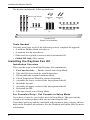
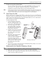
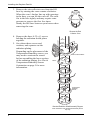
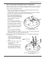
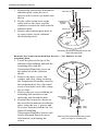
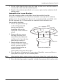
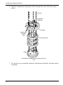
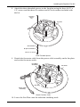
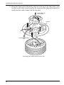
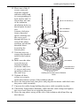
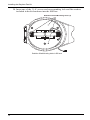
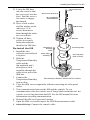
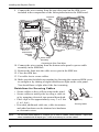
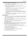
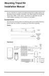
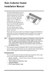
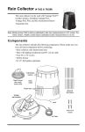
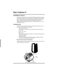
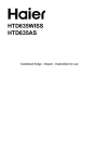
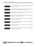
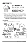
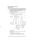
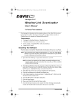
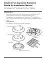
Daytime Fan-Aspirated Radiation
Shield Kit Installation Manual
For Vantage Pro2™ & Vantage Pro2 Plus™ Stations
Introduction
The instructions describe how to upgrade a non-aspirated Vantage Pro2™
radiation shield to a Daytime Fan-Aspirated Radiation Shield.
The upgrade kit can be installed on any Vantage Pro2™ or Vantage Pro2
Plus™ Integrated Sensor Suite (ISS) equipped with a non-aspirated radiation
shield.
Components
The upgrade kit includes the following components:
Closed Cap Plate
Fan Plate
Open Cap Plate
SIM Cover
Open Plate
Daytime Fan Kit Components
1
Installing the Daytime Fan Kit
The kit also includes the following hardware:
#8-32 x 3-1/4" Screws
(3)
1" Spacers
(2)
#4 Screws
(2)
#8 Split-Lock Washers (6)
#8-32 x 1/2" Screws
(3)
Threaded Spacers
(3)
#8 Flat Washers (6)
12" Cable Ties (2)
Daytime Fan Kit Hardware
Tools Needed
You may need some or all of the following tools to complete the upgrade:
•
•
•
•
A medium Phillips-Head screwdriver
A medium slot-tip screwdriver
Other tools as required to remove and re-mount the ISS
Cabled ISS Only: Wire cutters
Installing the Daytime Fan Kit
Installation Overview
These are the steps to install the Daytime Fan components:
1.
2.
3.
4.
5.
6.
7.
8.
9.
For Consoles Only — Put the console into Setup Mode.
Take the ISS down from its installed position.
Disassemble the standard radiation shield.
Check Temperature/Humidity sensor orientation.
Assemble the lower section of the fan-aspirated shield.
Install the fan unit.
Assemble the upper section of the fan-aspirated shield.
Re-Install the ISS.
Take the console out of Setup Mode.
For Consoles Only— Put Console in Setup Mode
If you have a console, you need to put it in Setup Mode. This prevents the
reception of erroneous data while you are removing the ISS.
If you have an Envoy and are concerned with erroneous data, you may edit the
data via the WeatherLink software. See the WeatherLink Online Help for more
information.
2
Installing the Daytime Fan Kit
To put your console in Setup Mode:
At your Vantage Pro2 console, press and hold DONE and then press the
down arrow (-) to put the console in Setup Mode. This prevents the
reception of erroneous data while you are removing the ISS.
Note:
If the console acquires erroneous data during the upgrade, see Take the Console Out
of Setup Mode on page 15 for instructions on clearing data. Additional information on
clearing console data can be found in the Vantage Pro2 Console Manual.
Take Down the ISS
Please work on your Vantage Pro2 ISS in a safe place. If you are installing the
Daytime Fan Kit on an ISS that has already been placed into service, you will
need to take down the ISS from its sited location and move it to a convenient
and safe place to perform the installation.
To disassemble the ISS:
1. Locate the Sensor Interface
Module (SIM) housing cover
on the side of ISS and open it.
Lift off cover,
unplug solar power
2. Disconnect the Solar Panel
connector
wire on the SIM cover from
the SIM board by pulling the
Solar Panel connector.
3. Pull the foam insert out of the
cable access port in between
the cables and set the foam
insert aside.
4. Disconnect the anemometer
cable from the sensor
connector labeled WIND and,
if you are using a cabled
model, disconnect the console
Detaching the SIM Cover
cable from the SIM and slide
the cables out of the cable
access port.
5. You can now remove the ISS from its mounted position. Move it to a safe
place to install the kit components.
Disassemble the Standard Radiation Shield
Note:
We recommend using a workbench or table to perform the following procedures.
1. Open and remove the SIM cover if you have not done so already.
2. Disconnect the Temperature/Humidity cable from the SIM and slide the
cable out of the cable access port.
3
Installing the Daytime Fan Kit
3. Remove the rain collector cone from the ISS
base by rotating the cone counter-clockwise.
When the cone’s latches line up with openings
in the base, you can lift the cone off. The cone
fits in the base tightly and may require extra
pressure to remove the first few times.
Steady the ISS base between your knees when
removing the cone
Twist to Open
Remove the Rain
Collector Cone
4. Remove the three 8-32 x 4'' screws
holding the radiation shield plates
together.
5. Save these three screws and
washers, and separate out the
radiation plating.
Depending on the placement of the
Temperature/Humidity sensor, you
may need to reorient the sensor
before assembling the lower section
of the radiation plating. See Check
Temperature/Humidity Sensor
Orientation on page 5 for more
information.
4"
Screw
Lock
Washer
Flat
Washer
Rain Collector Base
Plates
Temperature/
Humidity
Sensor
Standard Radiation Shield Assembly Diagram
Note: Placement of the Temperature/Humidity Sensor
may vary.
4
Installing the Daytime Fan Kit
Check Temperature/Humidity Sensor Orientation
The orientation and placement of the Temperature/Humidity sensor should be
checked, and in many cases, should be reoriented. There are three ways the
sensor could be mounted in an ISS:
• On the second to bottom-most plate of radiation plating stack with the
Temperature/Humidity sensor facing up.
• Underneath the top plate of the radiation plating stack, on the insulating
disk with the Temperature/Humidity sensor facing down.
• On the second to bottom-most
plate of the radiation plating stack
with the Temperature/Humidity
sensor mounted on spacers,
facing down.
If the Temperature/Humidity
sensor is mounted on the second
to bottom-most plate with the
sensor facing down, it is in the
correct orientation and does not
need to be repositioned in the
stack.
Temperature/Humidity Sensor correctly
If the Temperature/Humidity
mounted on spacers
Sensor is placed in one of the
other two positions, it should be removed from its current position and
remounted in the correct position shown above.
Reinstall the Temperature/Humidity Sensor — For Sensors Facing Up
1. Locate the
Temperature/Humidity sensor
on the second to bottom plate
in the radiation shield plating
stack.
2. Remove the three screws, flat
washer, and cable clamp
securing the
Temperature/Humidity sensor
to the radiation plating. Save
the small screw, flat washer,
and cable clamp for use later.
Temperature/Humidity
Sensor
Cable Clamp
Removing Temperature/Humidity Sensor with
sensor mounted up
5
Installing the Daytime Fan Kit
3. Reinstall the sensor face down on the
radiation plate, using the two 1'
spacers and #4 screws included with
the kit.
4. Put the cable clamp back on the
cable and use the screw and flat
washer to resecure the cable onto the
radiation plate.
5. Replace the radiation plate back in
its correct place in the radiation
shield plating stack.
#4 Screws (2)
Temperature/
Humidity
Sensor
Cable Clamp
Spacers (2)
Reinstalling Temperature/Humidity Sensor with
Sensor Mounted Down
Reinstall the Temperature/Humidity Sensor — For Sensors on the
Insulating Disk
1. Locate the plate at the top of the
radiation shield plating and find the
insulating disk with the
Temperature/Humidity sensor on
the underside of the radiation
shield.
2. Remove the three screws, flat
washer, and cable clamp securing
the Temperature/Humidity sensor to
the insulating disk. Save the small
screw, flat washer, and cable clamp
for use later.
3. Remove the two screws holding the
insulating disk attached on the
underside and discard the disk.
4. Reinstall the sensor face down on
the second to bottom-most radiation
plate, using the two 1' spacers and
#4 screws included with the kit. See
figure Reinstalling
Temperature/Humidity Sensor with
Sensor Mounted Down for more
information on mounting the
sensor.
6
Insulating
Disk
Temperature/
Humidity
Sensor
Cable
Clamp
Removing Temperature/Humidity Sensor with
sensor mounted on Insulating Disk
Installing the Daytime Fan Kit
5. Put the cable clamp back on the cable and use the screw and flat washer to
resecure the cable onto the radiation plate.
6. Replace the radiation plate back in its correct place in the radiation shield
plating stack.
Assemble the Lower Section
Once the existing radiation shield has been disassembled and the
Temperature/Humidity sensor has been mounted correctly in the radiation
plating stack, the existing disks have to be re-organized and assembled with
the fan-aspirated kit. To reassemble the radiation shield with the new
fan-aspirated shielding:
1. Locate the plate at the top
of the radiation shield
plating and find the
insulating disk on the
underside of the radiation
shield.
2. Remove the two screws
Top Plate
holding insulating disk
attached on the underside
and discard it. Save the top
plate for use in Step 3.
Insulating Disk
3. Start building the lower
section of the new radiation
shield, starting with the
original bottom plate on
Remove the Insulating Disk
bottom and the
disassembled top plate above that.
4. Place the plate containing the Temperature/Humidity sensor and the two
open plates on top of the two bottom plates.
Note:
When stacking plates, make sure the screw bosses (holes) line up with each other.
5. Place the third open plate (supplied with the fan-aspirated kit) on the stack.
7
Installing the Daytime Fan Kit
6. Run the Temperature/Humidity cable through the top of the three open
plates.
4" Screws
Lock Washer
Flat Washer
Fan Plate
Temperature/
Humidity
Cable
New Open Plate
Plates
Reassemble the Radiation Shield Plates with the Fan
Plate
7. Set aside the re-assembled radiation shielding and find the fan plate motor
assembly.
8
Installing the Daytime Fan Kit
8. Attach the three threaded spacers to the fan plate using the three #8-32 x
1/2'' screws and the three #8 washers and #8 lock washers included with
the kit.
Threaded
Spacer
(3)
Fan Plate
#8 Flat Washer
#8 Split-Lock Washer
#8-32 x 1/2" Screw
Install Threaded Spacers
9. Detach the fan motor cable from the power cable assembly on the fan plate
and set the fan motor aside.
Fan Motor
Assembly
Fan Plate
Fan Plug
Power Cable
Assembly
Detach Fan Motor Cable
10. Lower the Fan Plate onto the radiation shielding stack.
9
Installing the Daytime Fan Kit
11. Bring the Temperature/Humidity cable over the top of the fan plate so that
no slack in the cable exists between the sensor and the fan plate and press it
firmly into the cable channel on the fan plate.
Lift Fan Motor up
and set aside
Fan Plate
Channel
Temperature/Humidity
Cable
Connecting the Radiation Shield and Fan Unit
10
Installing the Daytime Fan Kit
12. Place one of the 4''
screws removed
from the original
radiation shield and
its corresponding #8
lock washer and # 8
flat washer into one
#8-32 x 4" Screws (3)
of the radiation
shield plate holes on
the fan plate located
#8 Lock Washer
just
#8 Flat Washer
counter-clockwise
from a threaded
spacer, making sure
the screw goes
through the boss in
each of the plates
and lines up with the
threaded insert
located in the
Fan Plate
bottom plate.
13. Turn the screw to
engage the threaded
insert in the bottom
plate.
14. Make sure the other
Screw Boss
screw bosses are
aligned and then
Threaded Insert
insert the other two
in Bottom Plate
4'' screws and corresponding washers in
Installing the Fan Plate onto the Radiation
the same way.
Shield
15. Tighten all three
screws to securely
fasten the bottom section of the radiation shield.
16. Place the fan motor back into place and plug the fan motor cable back into
the power cable assembly.
17. Unscrew the cable clamp holding the power cable assembly in place.
18. Thread the Temperature/Humidity cable into the cable clamp and tighten
the screw back down in its original placement.
19. Place the cap plates on top of the rest of the radiation shield and line up
their bosses.
11
Installing the Daytime Fan Kit
20. Insert one of the 3 1/4'' screws and corresponding lock and flat washers
included in the kit hardware into the ISS base
Radiation Shield Mounting Holes (3)
Radiation Shield Mounting Holes in ISS base
12
Installing the Daytime Fan Kit
21. Lower the ISS base
onto the stack so that
the screw goes into the
boss. Turn the screw a
few times to engage
the threads.
22. Place a lock washer
and flat washer on the
other two 3 1/4''
screws then insert
them through the other
two screw holes.
23. Tighten all three
screws to securely
fasten the radiation
shield to the ISS base.
Re-Install the ISS
Insert front screw
first
#8-32 x3-1/4" Screws (3)
#8 Lock Washers
#8 Flat Washers
SIM Housing
ISS Base
Temperature/
Humidity
Cable
Closed Cap Plate
1. Install the rain
collector cone and lock
Power Cable
Open Cap Plate
Assembly
it in place.
(hole in center)
2. Slide the
Temperature/Humidity
cable and the
fan-aspirated unit’s
solar power cable
Fan Plate
assembly through the
cable access port of the
SIM box.
3. Connect the
Reconnecting the Radiation Shield to the Rain Collector
Temperature/Humidity
sensor cable.
4. Close the SIM cover temporarily without connecting the solar panel
cables.
5. Test communication between the ISS and the console. To test
communication, take the console out of Setup Mode and make sure the
console is receiving data from the ISS. See the ISS manual for more
information on testing communication.
6. Reinstall the ISS in its previous location.
7. Open the SIM cover and connect the WIND (anemometer) cable.
8. Cabled ISS Only: Connect the console cable.
13
Installing the Daytime Fan Kit
9. Connect the wire coming from the top solar panel on the SIM cover
included in the components of the fan-aspirated unit to the SIM board.
Top Panel
Wire
Sensor
Interface
Module
(SIM)
SIM
Cover
Bottom Panel
Wire
Temperature/
Humidity
Cable
Power Cable
Assembly
Connecting the Solar Panel Wires
10. Connect the wire coming from the bottom solar panel to power cable
assembly in the SIM Box.
11. Reinsert the foam into the cable access port in the SIM box.
12. Close the SIM box.
13. Use cable ties to secure cables.
14. Make sure the fan blades are rotating by directing the connected SIM cover
to sunlight or by shining a bright incandescent light on the solar panel.
You should hear a slight whir if the fan is running.
Guidelines for Securing Cables
• Secure cables so they will not whip in the wind.
• Secure cables to metal poles by using a cable tie
or by wrapping electrical tape around them both.
• Place clips or ties approximately every 3 to 5 feet
(1 to 1.6 m).
• If needed, additional cable ties, cable tie mounts,
and other hardware can be obtained at a hardware
or electronics store.
Note:
14
Cable Tie
Cable Clip
Securing Cables
Do not use metal staples or a staple gun to secure cables. Metal staples—especially
when installed with a staple gun—have a tendency to cut the cables.
Maintenance
Take the Console Out of Setup Mode
1. At your Vantage Pro2 console, press and hold DONE for three seconds to
take the console out of Setup Mode.
2. Check the console for erroneous rain data and clear if necessary.
To clear erroneous daily rain data:
• Select the RAINDAY button. The graph icon displays next to the daily
rain variable.
• Press and release 2ND, then immediately press and hold CLEAR.
• The daily rain variable will start blinking.
• Keep holding CLEAR until the reading changes to zero.
• Refer to your Vantage Pro2 Console Manual for more information on
clearing any other weather variables or clearing all weather variables in
the console.
3. Congratulations! You have completed the upgrade and can now enjoy your
daytime fan-aspirated radiation shield.
Maintenance
• Keep the surfaces of the ISS clean, since the radiation shield and solar panel
are less effective when dirty. Remove dust from the solar panel and radiation shield with a damp cloth.
• Remove any debris obstructing air flow through the radiation shield such as
leaves, twigs, webs, and nests.
• Do not spray the ISS with insecticides of any kind. Some insecticides can
damage the sensors and even damage the radiation shield.
Annual Maintenance
We recommend cleaning out any debris that may have accumulated inside the
radiation shield and replacing the motor (# 7758) on an as needed basis. The
routine procedures for annual maintenance include:
1. Remove your fan-aspirated ISS and place on a stable work surface.
2. Check to see if the fan motor is still working. If it is not running, replace
the motor with a new motor (# 7758).
3. Disassemble the radiation shield.
4. Remove any debris lodged inside the unit.
5. Clean the surfaces of the radiation shield with a damp cloth.
6. Assemble the radiation shield.
7. Re-install the ISS in its previous location.
15
Contacting Davis Technical Support
If you are experiencing problems performing the upgrade or have problems
with your Daytime Fan-Aspirated Radiation Shield, first be sure to check all
cable connections. If you are unable to solve the problem, please call Davis
Technical Support. We’ll be glad to help. Most questions can be answered over
the phone. You can also email us for support or visit our website. Sorry, we are
unable to accept collect calls.
Note:
Please do not return items to the factory for repair without prior authorization.
(510) 732-7814 — Monday - Friday, 7:00 a.m. - 5:30 p.m. Pacific Time. We
are unable to accept collect calls.
(510) 670-0589 — Technical Support Fax.
[email protected] — E-mail to Technical Support.
[email protected] — General e-mail.
www.davisnet.com — Davis Instruments web site. See the Weather Support
section for copies of user manuals, product specifications, application notes,
and information on software updates. Watch for FAQs and other updates.
FCC Part 15 Class B Registration Warning
This equipment has been tested and found to comply with the limits for a Class B digital device, pursuant to Part 15 of the FCC Rules.
These limits are designed to provide reasonable protection against harmful interference in a residential installation. This equipment
generates, uses, and can radiate radio frequency energy and, if not installed and used in accordance with the instructions, may cause
harmful interference to radio communications.
However, there is no guarantee that interference will not occur in a particular installation. If this equipment does cause harmful interference to radio or television reception, which can be determined by turning the equipment on and off, the user is encouraged to try to
correct the interference by one or more of the following measures:
•
Reorient or relocate the receiving antenna.
•
Increase the separation between the equipment and receiver.
•
Connect the equipment into an outlet on a circuit different from that to which the receiver is connected.
•
Consult the dealer or an experienced radio/TV technician for help.
Changes or modification not expressly approved in writing by Davis Instruments may void the warranty and void the user's authority
to operate this equipment.
EC EMC Compliance
This product complies with the essential protection requirements of the EC EMC
Tested to comply
Directive 89/336/EC.
with FCC standards
FOR HOME OR OFFICE USE
Addendum, Fan-Aspirated ISS Installation
Document Part Number: 7395.236
Product Number:7747
Rev. B, February 7, 2008
Vantage Pro® and Vantage Pro2™ are trademarks of Davis Instruments Corp., Hayward, CA.
© Davis Instruments Corp. 2008. All rights reserved.
Information in this document subject to change without notice.
3465 Diablo Avenue, Hayward, CA 94545-2778 U.S.A.
510-732-9229 • Fax: 510-732-9188
E-mail: [email protected] • www.davisnet.com