1
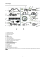
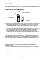
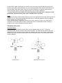
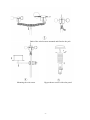
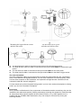
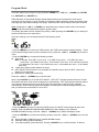
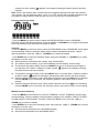
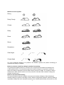
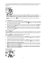
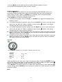
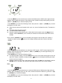
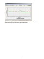
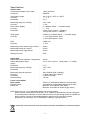
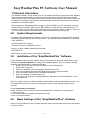
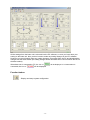
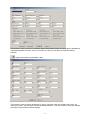
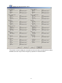
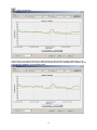
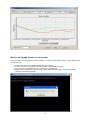
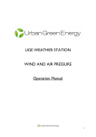
PROFESSIONAL WEATHER STATION (WIND AND AIR PRESSURE) Operation Manual This manual will guide you through step-by-step instructions to help you set up your device. Use this manual to become familiar with your professional weather station and please save it for future reference. Glossary of Common Terms DCF/WWVB/MSF The DCF, WWVB or MSF time signal is an AM modulated time-of-day signal broadcasted by the Federal Government of Germany, NIST from USA or National Physical Laboratory in the UK. The time base is generated from an atomic time generator which is accurate to 10 billions of one second. LCD “LCD” is an acronym for ”Liquid Crystal Display”. This is a common type of display screen used in televisions, computers, watches, and digital clocks. BAROMETER & BAROMETRIC PRESSURE A barometer is a device that measures the pressure of the air pushing on it—this measurement is called the barometric pressure. We don’t actually feel the barometric pressure because the air pressure is pushing equally in every direction. RELATIVE AIR PRESSURE Relative air pressure is the same as the barometric pressure. The calculation of relative air pressure is a combination of the absolute air pressure and the altitude. ABSOLUTE AIR PRESSURE Absolute air pressure is the actual air pressure on the barometer without regard to altitude. INCHES OF MERCURY (in Hg) Inches of Mercury is the common unit of measurement for air pressure in the United States. Hectopascal (symbol hPa) is a SI unit, the international system of units now recommended for all scientific purposes. Millibar (symbol mb or mbar) is a meteorological unit of pressure equal to one-thousandth of a bar. A bar is a c.g.s. unit of pressure (A system of units based on the centimeter, gram and second) equal to 1,000,000 dynes per square centimeter, or 100,000 pascals (symbol Pa). Thus one millibar is equivalent to 100 pascals or one hectopascal. An added feature of the Weather Station is the readout of all measurements, displayed time and weather data on a personal computer. -1- LCD display 7. 8. 9 10 1. 11. 12. 2. 13. 3. 14 4. 5. 15. 6. 16. 18 1. 2. 3. 4. 5. 6. 7. 8. 9. 10. 11. 12. 13. 14. 15. 16. 17. 18. 17. Weather Forecast Barometric Pressure Barometric trend Date Memory used Time Indoor Humidity Indoor Temperature Low battery indicator for the transmitter Outdoor reception signal indicator Outdoor Humidity Outdoor Temperature gauge Wind direction indicator Wind speed/gust gauge UV index Rainfall gauge Light intensity Radio Controlled Clock (RCC) Note: The presence of the "Alarm-On icon" in the section means that the particular alarm has been enabled. -2- Set up Guide Before placing and installing all components of the weather station at there final location, please set up the weather station with all parts nearby for testing the correct operation. Setting up the base station and transmitter Setting up using batteries: Thermo-hygro Sensor LED Indicator Sensor Sockets Battery Compartment Battery cover 1) Insert 2XAA 1.5V rechargeable batteries first into the battery compartment of the remote sensor and immediately afterwards 3XAA 1.5V alkaline batteries in the base station, observing the correct polarity. When battery is first inserted, the red LED light on the remote sensor will be light up for 3-4 seconds. (If the LED does not light up or the LED shows a steady light, make sure the battery is inserted the correct way round or a proper reset has happened) 2) When the base station is powered up, the LCD display activates for 3 seconds and after the “Beep”, it begins measuring indoor temperature, humidity and air pressure. The unit then enter the RF (Radio Frequency) state, where it receives data from the remote sensor and RCC (Radio Controlled Clock) receiving state at the same time. During radio controlled time reception period, there is no transmission and normal transmission will only resume after time reception routine is complete. The longest time for radio controlled time reception is 5 minutes. RF (Radio Frequency) Receiving Mode 1. After power-on, the weather station enters RF receiving state for 144 seconds. 2. The base station expects to receive the temperature, humidity, wind speed and rain data every 48 seconds and receive illuminance date every 60 seconds. If there is a loss of signal for any reason and the base station has missed 8 successive data packets, the outdoor temperature and humidity will display “----”. The base station will start search the new remote sensor signal for 144 seconds. 3. If the outdoor data is lost or the battery has been changed in the transmitter, press the reset button on the solar power module to re-send the signal and hold the “▼” key for 4 seconds to enter manual RF receiving state. 4. Do not press any key before outdoor sensor data received, otherwise the outdoor sensor learning mode will be terminated. When outdoor transmitter has been registered, the base station will automatically switch to the normal display mode from which all further settings can be performed by the user. 5. If there is no temperature reading in the indoor station, make sure the units are within range of each other or reinstall the batteries as described previously. RCC (Radio Controlled Clock) Receiving Mode 1. After the hygro-thermo sensor is powered up, the sensor will transmit weather data for 24 seconds, and then the sensor will start radio controlled time reception. During the RCC time reception period a maximum 5 minutes, no weather data will be transmitted. 2. If no RCC signal is detected in the initial setup, the thermo-hygro sensor will try once every hour -3- to get an RCC signal until a signal is received. Once the sensor receives the RCC signal it will transmit the signal to the base station, the received time and date will overwrite the manually set time and date, on the base station the RCC icon will be displayed. If the base station doesn’t receive the RCC signal or loses the signal the RCC icon will not be displayed. 3. If your time zone is not at UTC+1:00, then manually set the time zone so that your clock time will be updated correctly after radio controlled time is received. Note: Commonly the radio communication between receiver and transmitter in the open field can reach a distance of up to 100 metres providing that there are no interfering obstacles such as buildings, trees, vehicles, high voltage lines, etc. Radio interference from equipment such as PC screens, radios or TV sets can, in bad cases, completely cut off radio communication. Please take this into consideration when choosing a location for the outdoor transmitter and base station. Mounting the sensor Important Notes: On the sides of wind direction sensor, there are four alphabet letter of “N”,”E”,”S”and “W” representing the direction of North, East, South and West. The wind direction sensor has to be adjusted so that the directions on the sensor are matching with your real location. A permanent wind direction error will be introduced when the wind direction sensor is not positioned correctly during installation. Anemometer wind direction sensor -4- Both of the wind sensors mounted and fitted to the pole Mounting the rain sensor Hygro-thermo sensor with solar panel -5- Mounting the hygro-thermo sensor and the rain sensor Fix the whole set to a pole with the two Jubilee clips. The anemometer’s cable is connected to the input on the wind direction sensor. The wind direction sensor’s cable is connected to the input marked Wind on the thermo-hygro sensor The rain sensor’s cable is connected to the input marked Rain on the solar panel The solar panel’s cable is connected to the input marked Rain on the thermo-hygro sensor. The solar transmitter The solar transmitter makes use of solar energy to power the instruments they are connected to. Note: It uses AA size rechargeable batteries. For the solar transmitter to function properly, make sure the solar receptors on the transmitter- are exposed to sunlight and the connectors of the connection cable are securely plugged in. For best results set up the solar panel facing south if you live in the northern hemisphere or facing north if you live in the southern hemisphere. Positioning Once you have verified that all of the components of the weather station are working, they can be installed in their permanent position. Before permanently mounting the equipment, make sure that all components work properly together at their chosen location. If e.g. there appears to be a problem with the 433 MHz radio transmission, they can mostly be overcome by moving the mounting location. -6- Program Mode The base station has six keys for easy operation: MENU key, ▲(UP) key, ▼(DOWN) key, ENTER key, HISTORY key, ON/OFF key Note: Because of the default settings already determined by the manufacturer it will not be necessary for the majority of user to perform (except the relative pressure please see further down this page) any other basic settings or changes, however these can be easily made when required. Note: Keeping the ▲(UP) or ▼(DOWN) key depressed when setting certain units in the manual setting mode will increase/decrease digits in greater steps. The setting procedure can be exited at any time by either pressing the HISTORY key or waiting for the 30-second time-out to take effect. The basic settings can now be performed in the following order: Time - Press the MENU key to select the TIME section, the TIME section digits will start flashing. Enter LCD contrast setting mode (level 0-8, default level 5), press the ▲(UP) or ▼(DOWN) key to set the value. - Press the ENTER key to select the following modes: Time zone Note: In Europe, 0 for GMT+1 time zone, 1 for GMT+2 time zone, -1 for GMT time zone. In America, -4 for Atlantic time zone, -5 for Eastern Time zone, -6 for Central Time Zone, -7 for Mountain Time zone, -8 for Pacific time zone, -9 for Alaska time zone, -10 for Hawaii time zone. 12/24h time display select (default 12 hours) DST ON/OFF (this function is only available for WWVB version, while for DCF version this feature is not activated) Manual time setting (hours/minutes) Press the ▲(UP) or ▼(DOWN) key to set the value. Note: Press ON/OFF key to set the DST ON/OFF. “DST OFF” indicates that the feature is off and the internal real time clock will not change times automatically. “DST ON” indicates that the feature is on and the internal real time clock will change times according to the DST time schedule automatically. Some locations (Arizona and parts of Indiana) do not follow Daylight Saving Time, and you should ensure that DST is set to OFF”. Date - Press the MENU key twice to select the DATE section, the DATE section digits will then start flashing. Enter DD-MM-SECOND/DD-MM-WEEK/Time alarm display mode. (Default DD-MM-SECOND format), press the ▲(UP) or ▼(DOWN) key to select the display mode. - Press the ENTER key to select the following modes, press the ▲(UP) or ▼(DOWN) key to set the value: Select DD-MM or MM-DD format. (Default DD-MM format) Calendar setting (year/month/date) Time alarm setting. (Hours/minutes). Press the ON/OFF key to on/off the alarm. If alarm is -7- enabled, an alarm symbol appears in the display indicating the alarm function has been enabled. Note: When a set weather alarm condition has been triggered that particular alarm will sound for 120 seconds. The corresponding value, ‘HI AL” or “LO AL” and the alarm symbol are flashing until the weather condition doesn’t meet the user set level. Press any key to mute the alarm. Pressure history bar graph - Press the MENU key the third time to select the PRESS HISTORY section, PRESSURE HISTORY section digit will start flashing. Press the ▲(UP) or ▼(DOWN) key to toggle the bar graph time scale between 12hrs and 24 hrs for pressure history. Pressure - Press the MENU key the fourth time to select the PRESSURE section, PRESSURE section digits will start flashing. Enter the pressure display mode (relative and absolute pressure. Default absolute pressure), press the ▲(UP) or ▼(DOWN) key to select the display. - Press ENTER key to select the following modes, then press the UP/+ or ▼(DOWN) key to select the display or set the value: Select pressure unit between hPa, mmHg, inHg. (Default hPa). The relative pressure setting. (If you select absolute pressure display, skip this step) The pressure high alarm setting. Press the ON/OFF key to turn on the alarm press again to turn the alarm off. If alarm is enabled, an alarm symbol appears in the display indicating the alarm function has been enabled The pressure low alarm setting. Press the ON/OFF key to on/off the alarm. If alarm is enabled, an alarm symbol appears in the display indicating the alarm function has been enabled Reset the maximum pressure value. When both the pressure value and MAX icon are flashing, hold the ENTER key for 3 seconds, the maximum pressure value will be reset to current reading. Reset the minimum pressure value. When both the pressure value and MIN icon are flashing, hold the ENTER key for 3 seconds, the minimum pressure value will be reset to current reading. Weather forecast tendency - Press the MENU key the fifth time to select the TENDENCY section, TENDENCY section digits will start flashing. Enter the weather forecast tendency display mode (SUNNY, PARTLY CLOUDY, CLOUDY NIGHT, CLEAR NIGHT, CLOUDY, RAINY and SNOW icon), press the ▲(UP) or ▼ (DOWN) key to select the display. - Press ENTER key to select the following modes, then press the ▲(UP) or ▼(DOWN) key to select the display or set the value: Set the pressure threshold from 2-4hPa(default 2hPa) Set the storm threshold from 3-9hPa(default 4hPa) -8- Weather forecast symbol: Sunny Partly Cloudy Cloudy Rainy Snow Storm Snowstorm Clear Night Cloudy Night For every significant change in air pressure, the weather symbols will update accordingly to represent the change in weather. Notes to pressure sensitivity setting for weather forecasting: The pressure threshold can be set to suit the user’s requirement for weather forecasting from 2-4hPa (default 2hPa). For areas that experience frequent changes in air pressure requires a higher hPa setting compared to an area where the air pressure is stable. For example if 4hPa is selected, then there must be a fall or rise in air pressure of at least 4hPa needed to change the weather forecast icons. Notes to storm threshold setting The storm threshold means the weather icons (rain and clouds) will begin to flash indicating a dramatic change in pressure, indicating a storm. Similar to the general pressure sensitivity setting it is possible to adjust the storm threshold sensitivity form 3-9hPa (default 4hPa). When there is a fall -9- over pressure threshold within 3 hours, the storm forecasting will be activated, the clouds with rain icon and tendency arrows will flash for 3 hours indicating the storm warning feature has been activated. Indoor humidity - Press the MENU key the sixth time to select the INDOOR HUMIDITY section, the INDOOR HUMIDITY section digits will start flashing. To enter the indoor humidity high alarm setting mode, press the ON/OFF key to turn on the alarm press again to turn the alarm off. If the alarm is enabled, an alarm symbol appears in the display indicating the alarm function has been enabled - Press ENTER key to select the following modes: The indoor humidity low alarm setting. Press the ON/OFF key to turn on the alarm press again to turn the alarm off. If alarm is enabled, an alarm symbol appears in the display indicating the alarm function has been enabled Reset the maximum indoor humidity value. When both the indoor humidity value and MAX icon are flashing, hold the ENTER key for 3 seconds, the maximum indoor humidity value will be reset to current reading. Reset the minimum indoor humidity value. When both the indoor humidity value and MIN icon are flashing, hold the ENTER key for 3 seconds, the minimum indoor humidity value will be reset to current reading. Indoor temperature - Press the MENU key the seventh time to select the INDOOR TEMPERATURE section, INDOOR TEMPERATURE section digits will start flashing. To enter the temperature unit mode, press the ▲ (UP) or ▼(DOWN) key to toggle temperature unit between ℃ and ℉ - Press ENTER key to select the following modes: The indoor temperature high alarm setting. Press the ON/OFF key to turn on the alarm press again to turn the alarm off. If alarm is enabled, an alarm symbol appears in the display indicating the alarm function has been enabled The indoor temperature low alarm setting. Press the ON/OFF key to turn on the alarm press again to turn the alarm off. If alarm is enabled, an alarm symbol appears in the display indicating the alarm function has been enabled Reset the maximum indoor temperature value. When both the indoor temperature value and MAX icon are flashing, hold the ENTER key for 3 seconds, the maximum indoor temperature value will be reset to the current reading. Reset the minimum indoor temperature value. When both the indoor temperature value and MIN icon are flashing, hold the ENTER key for 3 seconds, the minimum indoor temperature value will be reset to the current reading. Outdoor humidity - 10 - - Press the MENU key the eighth time to select the OUTDOOR HUMIDITY section, The procedures and settings are similar to Indoor humidity Outdoor temperature - Press the MENU key the ninth time to select the OUTDOOR TEMPERATURE section, the OUTDOOR TEMPERATURE section digits will start flashing. Enter the outdoor temperature display mode, press the ▲(UP) or ▼(DOWN) key to select the outdoor temperature display between Outdoor Temperature, Wind Chill and Dew Point. - Press ENTER key to select the following modes: Temperature unit display. Press the ▲(UP) or ▼(DOWN) key to toggle the temperature unit between ℃ and ℉ The outdoor temperature high alarm setting. Press the ON/OFF key to turn on the alarm press again to turn the alarm off. If alarm is enabled, an alarm symbol appears in the display indicating the alarm function has been enabled The outdoor temperature low alarm setting. Press the ON/OFF key to turn on the alarm press again to turn the alarm off. If alarm is enabled, an alarm symbol appears in the display indicating the alarm function has been enabled Reset the maximum outdoor temperature value. When both the outdoor temperature value and MAX icon are flashing, hold the ENTER key for 3 seconds, the maximum outdoor temperature value will be reset to the current reading. Reset the minimum outdoor temperature value. When both the outdoor temperature value and MIN icon are flashing, hold the ENTER key for 3 seconds, the minimum outdoor temperature value will be reset to the current reading. UV index The UV intensity indicators is to show the UV intensity level from 0-12 UV Index Extreme Very high High Moderate Low : : : : : 10, 11, 12+ 7, 8, 9 5, 6 3, 4, 0, 1, 2 -Press the MENU key the tenth time to enter UV high alarm setting, Press the ON/OFF key to turn on the alarm press again to turn the alarm off. If alarm is enabled, an alarm symbol appears in the display indicating the alarm function has been enabled - Press ENTER key to reset the maximum UV index value. When both the UV index value and MAX icon are flashing, hold the ENTER key for 3 seconds, the maximum UV index value will be reset to the current reading. Wind - 11 - - Press the MENU key the eleventh time to select the WIND section, WIND section digits will start flashing. Enter average wind speed / Gust display mode. (Default average wind speed), press the ▲(UP) or ▼(DOWN) key to select the display mode. - Press ENTER key to select the following modes, then press the ▲(UP) or ▼(DOWN) key to select the display or set the value: Select the wind speed unit between km/h, mph, m/s, knots, bft (Beaufort scale). The default is mph. The wind speed high alarm setting. The wind direction alarm setting. Reset the maximum wind speed value. When both the wind speed value and MAX icon are flashing, hold the ENTER key for 3 seconds, the maximum value will be reset to the current reading. Note: Press the ON/OFF key to turn on the alarm press again to turn the alarm off. If alarm is enabled, an alarm symbol appears in the display indicating the alarm function has been enabled Light - Press the MENU key the twelfth time to select the LIGHT section, LIGHT section digits will start flashing. Enter the light unit mode, press the ▲(UP) or ▼(DOWN) key to select light intensity unit between W/M2, FC and LUX - Press ENTER key to select the following modes: The light high alarm setting. Press the ON/OFF key to turn on the alarm press again to turn the alarm off. If alarm is enabled, an alarm symbol appears in the display indicating the alarm function has been enabled Reset the maximum light value. When both the light value and MAX icon are flashing, hold the ENTER key for 3 seconds, the maximum light value will be reset to the current reading. Rain - Press the MENU key the thirteenth time to select the RAIN section, RAIN section digits will start flashing. Enter rain display mode (1h, 24h, week, month and total rain. Default 1h), press the ▲(UP) or ▼(DOWN) key to select the display. - Press ENTER key to select the following modes, then press the ▲(UP) or ▼(DOWN) key to select the display or set the value: - 12 - Select rain fall unit between mm, inch. (Default mm) The rain high alarm setting. Press the ON/OFF key to turn on the alarm press again to turn the alarm off. If alarm is enabled, an alarm symbol appears in the display indicating the alarm function has been enabled Reset the maximum rainfall value. When both the rain value and MAX icon are flashing, hold the ENTER key for 3 seconds, the maximum rain value will be reset to the current reading. Clear the total rainfall. When both the total rain value and CLEAR word are flashing, hold the ENTER key for 3 seconds, the total value will be reset to zero. 1h, 24h, week, month rain value will be reset to zero automatically. Memory modes 1) Press the HISTORY key to activate history data toggle display, Press ▼(DOWN) key to toggle forward to see earlier weather history data together time stamp, press ▲(UP) key to see later history weather data. When history data displayed, the corresponding time will be displayed at the time section area (History data saving interval can only be changed using the PC software that comes with this product, the default history data saving time interval is preset to 30 minutes prior to shipment). 2) Press the ENTER key will trigger the memory clear procedure: the word of “CLE” will be flashing; the full memory usage icon will be flashing. Holding down the ENTER key for 3 seconds will clear the memory. Reset To Factory Default Settings While in normal display mode, press and hold the ▲(UP) key for 20 seconds to reset to the manufacturer default settings. PC Connection As an important feature in addition to the display, the Weather Station allows the read-out of all measured and displayed time and weather data in form of complete history data sets on a PC. Data Storage For a comprehensive weather history, the Base Station allows the internal storage of up to 4080 complete sets of weather data with time and date. These data sets are being stored in non-volatile ring buffer memory (EEPROM) and will not be lost even in case of an interruption of power supply (e. g. a change of batteries). In case the memory capacity of the Weather Station is exceeded the oldest data sets stored will be overwritten by the new ones entered. Data Recall Certain weather data or setting values can only be read out, processed, and displayed by means of a PC. Also the settings of the storing intervals from 5 minutes to 240 minutes for the storage of data sets can only be performed by means of a PC. Connections and Software The wiring between Weather Station and PC takes place by means of an included USB cable. The EasyWeatherPlus software package, also included in the shipping contents, must be installed on the PC. This software allows the display of all present weather data with graphic symbols. It also allows the - 13 - display, storage, and printing of history data sets, whose volume exceeding the maximum 408 0 data sets of the Weather Station is only limited by the capacity of the PC’s main memory. PC software installation The installation of software is very simple: double click the setup.exe file and follow the steps that pop up. Make sure you are running the program under the administrator accounts of your windows PC platform. Otherwise the graphic function might not work when graph display mode is needed to display all history data. If you run the program for the first time, the current weather display will be displayed and at the sub line of the window, the program will show related information regarding the read of all history data into the PC. Please note however, when there is large amount of data is being uploaded, it will take a few minutes time before the system can respond to your setup settings. Otherwise it will display “read weather data fail” error message since the USB port is reading the data from the memory and the system is not able to respond any further job tasks. - 14 - When memory is full, it will take about two minutes to upload all history data into PC and it takes another two minutes to process all history data for graphic display. - 15 - Specifications Outdoor data Transmission distance in the open Frequency : : 100m (330 feet) 868 MHz Temperature range Accuracy Resolution : : : -40˚C--60˚C (-40℉ to +140℉) + / - 1 °C 0.1˚C Measuring range rel. humidity Accuracy : : 10%~99% +/- 5% Rain volume display Accuracy Resolution : : : 0 – 9999mm (show --- if outside range) + / - 10% 0.3mm (if rain volume < 1000mm) 1mm (if rain volume > 1000mm) Wind speed Accuracy: : 0-50m/s (0~100mph) (show --- if outside range) +/- 1m/s (wind speed< 5m/s) +/-10% (wind speed > 5m/s) Light Accuracy : : 0-400k Lux +/-15% Measuring interval thermo-hygro sensor : Measuring interval UV sensor : Measuring interval Light sensor : 48 sec 60 sec 60 sec Water proof level IPX3 : Indoor data Measuring interval pressure / temperature: Indoor temperature range : range) Resolution : 48 sec -10˚C--60˚C (14℉ to + 140℉) (show --- if outside 0.1˚C Measuring range rel. humidity Resolution : : 10%~99% 1% Measuring range air pressure Accuracy Resolution Alarm duration : : : : 300-1100hPa (8.85-32.5inHg) +/-3hpa under 700-1100hPa 0.1hPa (0.01inHg) 120 sec Power consumption Base station Remote sensor Battery life : : : 3XAA 1.5V LR6 Alkaline batteries (not included) 2xAA alkaline rechargeable batteries (included) Minimum 12 months for base station Minimum 24 months for thermo-hygro sensor Note: Be sure to use 1.5V rechargeable battery for solar transmitter. Where outdoor temperature is lower than -20˚C, make sure the batteries used are designed for low temperature operation to assure that the device can get enough power to maintain its proper function. Normal re-chargeable batteries should not be used when outdoor temperature is lower than -20 ˚C, the battery’s capacity is greatly reduced. Please help in the preservation of the environment and return used batteries to an authorized depot. - 16 - EasyWeatherPlus PC Software User Manual 1.0 General Information This Weather Station is a high quality, easy to use weather monitoring system that reads, displays and records the weather data from internal as well as external sensors. Besides the internally measured values for indoor temperature, indoor humidity and air pressure the outdoor sensor will take data for temperature and humidity, wind and rainfall. Operation of these units is by wireless transmission to the Base Station. After installing the “EasyWeatherPlus” program on this CD-ROM, your PC can display all indoor data as well as the weather data from the Base Station received from the external sensors. For operation, simply use the USB cable supplied and connect the Base Station to the PC. From now on you can start to track current and history weather information at your finger tips. 2.0 System Requirements To install the "EasyWeatherPlus" software onto your PC, the minimum requirements are as follows: Operating System: Windows NT4 (Service Pack >= 6a), Windows 2000, Windows XP, Windows Vista, Windows 7. Internet Explorer 6.0 or above Processor: Pentium III 500 MHz or above Memory: at least 128MB, 256MB recommended CD-ROM Drive Base Station and PC must be connected by USB cable 3.0 Installation of the “EasyWeatherPlus” Software Firstly, the Base Station and the Outdoor Sensors should be connected and checked for correct function (see Operation Manual for setting up the Weather Station). After successful checking, install the “EasyWeatherPlus” software as follows: 1. Switch on your PC and insert the CD-ROM into the CD-ROM Drive. 2. Double click “Setup.exe” 3. Select the installation process language option and click next 4. click next and select the destination folder(change directory when needed) 5. click next and the software will be installed automatically 6. press ok to finish the installation process 7. From “Start—All Programs—EasyWeatherPlus” path and the “EasyWeatherPlus” icon to start application. Note: The graphic function needs the software to be installed under the administrator account. If it is installed under limited user accounts, the graphic function of the software might not work correctly. To run easyweather in windows7 Please note that end user should run the easyWeatherPlus in windows7 as administrator: 1. Click “start” icon 2. Find easyWeatherPlus program and right click mouse 3. Click “run as administrator” 4.0 Basic Settings of the “EasyWeatherPlus” Software After the “EasyWeatherPlus.exe” program has been started, the following main window will appear on the PC screen: - 17 - All the settings from the base unit is mirrored into the PC software, so once you have done your setting on the base unit, then you don’t need to make any setting changes on the PC software. However you can still easily make any setting changes you wanted from the PC and download the changes into the base station (the setting change will be refreshed when next full minute arrives on the base station). When base unit is connected to PC, the icon of connected, the icon of will be displayed. If no base station is will be displayed. Function button: : Display and setup system configuration - 18 - This section is used to set up PC software display, base station units, as well as able or disable the corresponding alarm function. Once you made your choice, press Save to make the setting effective. : Display and modify system alarm value This section is used to set the desired time, high or low alarm value for the base unit. Once you made your choice, choose Save to make the setting effective. If you don’t want to make any change, just press Cancel and exit without change. - 19 - : Display min and max history value This section is used to display the recorded min and max value recorded with time stamp. Min/Max reset can only be done through key operation on the base station. - 20 - : display history detail data This section is used to display recorded history data in a spread sheet. If you wanted to see all history data in a desired time period, choose the time duration and press Search to reload the history data. With the Export button, you can export the selected history data into text format file for other application purpose. When memory on base station is full, press “Clear Memory” button to refresh the memory space on the base station (remember to upload all data before pressing this button). If you wanted to start a new weather history record, press “Clear Data” button to clear up the data base, all history weather data will be deleted (if you would like to keep a back up history file before deleting all weather data, you can make a copy of the “EasyWeatherPlus.dat” file into another folder or just rename the “EasyWeatherPlus.dat” file, such as “Jan-07.dat”, for future reference. - 21 - : display graph data In this section, you can see the history data plotted in graph format for easier observation. If you want to see more details, just use your mouse to select the area you wanted and the display will be automatically updated in more detailed scale: - 22 - What to do if graph function is not working This is the most encountered problem with this software. To make the graph function working properly, please check the following step: 1, find the folder where the “EasyWeatherPlus.exe” file is located 2. Create a file name “reg_graph.bat” file with WordPad or Notepad editor program 3. Type “regsvr32 easyweatherplus.ocx” and save the reg_graph.bat file 4. Double click “reg_graph.bat” file and it should register the graphic driver again. If successful, then the following window will be displayed: - 23 - Special Notes about time synchronization between PC and sub-station: The PC software obtained its own time scale through the time interval marker from the base station history data, and the PC software automatically synchronizes the weather data with a time stamp calculated. Thus the history data file can have different time when the PC time and base station time is not same. In order to make the time scale correct, remember to set the PC time and base station time same, and further to this, no weather data is allowed to be missed or over-written. If history weather memory on the base station is cleared by manual setting, then the history weather data since last uploading is lost permanently. Before memory is used up (memory icon on LCD display showing 100% full), remember to upload weather history data to PC periodically. If there is a reset happened for the rain fall on the base station, then there will be rain fall value discrepancy between PC and base station. Legal Notes We reserve the right to delete or change any image whether or not purposely uploaded onto the server by a user of the EasyWeather software products. The EasyWeather software products are protected by copyright laws and international copyright treaties as well as other intellectual property laws and treaties. You may not copy the printed materials accompanying the products. All rights reserved. This handbook must not be reproduced in any form, even in excerpts, or duplicated or processed using electronic, mechanical or chemical procedures without written permission of the publisher. This handbook may contain mistakes and printing errors. The information in this handbook is regularly checked and corrections made in the next issue. We accept no liability for technical mistakes or printing errors, or their consequences. All trademarks and patents are acknowledged. - 24 -