1
Model: 4033, 4034
50 MHz Programmable Pulse
Generator
USER MANUAL
Safety Summary
The following safety precautions apply to both operating and maintenance personnel and must be
observed during all phases of operation, service, and repair of this instrument. Before applying power,
follow the installation instructions and become familiar with the operating instructions for this
instrument.
Failure to comply with these precautions or with specific warnings elsewhere in this manual violates
safety standards of design, manufacture, and intended use of the instrument. B&K PRECISION
assumes no liability for a customer’s failure to comply with these requirements.
GROUND THE INSTRUMENT
To minimize shock hazard, the instrument chassis and cabinet must be connected to an electrical
ground. This instrument is grounded through the ground conductor of the supplied, three-conductor ac
power cable. The power cable must be plugged into an approved three-conductor electrical outlet. Do
not alter the ground connection. Without the protective ground connection, all accessible conductive
parts (including control knobs) can render an electric shock. The power jack and mating plug of the
power cable meet IEC safety standards.
DO NOT OPERATE IN AN EXPLOSIVE ATMOSPHERE
Do not operate the instrument in the presence of flammable gases or fumes. Operation of any electrical
instrument in such an environment constitutes a definite safety hazard.
KEEP AWAY FROM LIVE CIRCUITS
Instrument covers must not be removed by operating personnel. Component replacement and internal
adjustments must be made by qualified maintenance personnel. Disconnect the power cord before
removing the instrument covers and replacing components. Under certain conditions, even with the
power cable removed, dangerous voltages may exist. To avoid injuries, always disconnect power and
discharge circuits before touching them.
DO NOT SERVICE OR ADJUST ALONE
Do not attempt any internal service or adjustment unless another person, capable of rendering first aid
and resuscitation, is present.
DO NOT SUBSTITUTE PARTS OR MODIFY THE INSTRUMENT
Do not install substitute parts or perform any unauthorized modifications to this instrument. Return the
instrument to B&K Precision for service and repair to ensure that safety features are maintained.
WARNINGS AND CAUTIONS
WARNING and CAUTION statements, such as the following examples, denote a hazard and appear
throughout this manual. Follow all instructions contained in these statements.
A WARNING statement calls attention to an operating procedure, practice, or condition, which, if not
followed correctly, could result in injury or death to personnel.
A CAUTION statement calls attention to an operating procedure, practice, or condition, which, if not
followed correctly, could result in damage to or destruction of part or all of the product.
WARNING:
Do not alter the ground connection. Without the protective ground connection, all
accessible conductive parts (including control knobs) can render an electric shock.
The power jack and mating plug of the power cable meet IEC safety standards.
WARNING:
To avoid electrical shock hazard, disconnect power cord before removing covers.
Refer servicing to qualified personnel.
2
CAUTION:
Before connecting the line cord to the AC mains, check the rear panel AC line
voltage indicator. Applying a line voltage other than the indicated voltage can
destroy the AC line fuses. For continued fire protection, replace fuses only with
those of the specified voltage and current ratings.
CAUTION:
This product uses components which can be damaged by electro-static discharge
(ESD). To avoid damage, be sure to follow proper procedures for handling, storing
and transporting parts and subassemblies which contain ESD-sensitive
components.
Compliance Statements
Disposal of Old Electrical & Electronic Equipment (Applicable in the European
Union and other European countries with separate collection systems)
This product is subject to Directive 2002/96/EC of the
European
Parliament and the Council of the European Union on waste
electrical and electronic equipment (WEEE) , and in
jurisdictions
adopting that Directive, is marked as being put on the market
after August 13, 2005, and should not be disposed of as
unsorted
municipal waste. Please utilize your local WEEE collection
facilities in the disposition of this product and otherwise
observe all applicable requirements.
Safety Symbols
Connect to safety earth ground using the wire recommended in the user manual.
This symbol on an instrument indicates that the user should refer to the operating
instructions located in the manual.
Electrical Shock hazard.
3
Table of Contents
Safety Summary .............................................................................................. 2
Section 1 .......................................................................................................... 6
Introduction ........................................................................................................................ 6
1.1
1.2
1.3
1.4
Introduction .............................................................................................................................................. 6
Description ............................................................................................................................................... 6
Safety Remarks ....................................................................................................................................... 6
Package Contents ................................................................................................................................... 6
Specifications..................................................................................................................... 6
Section 2 .......................................................................................................... 9
Installation .......................................................................................................................... 9
2.1 Introduction .............................................................................................................................................. 9
2.2 Mechanical Inspection ............................................................................................................................. 9
2.3 Initial Inspection ....................................................................................................................................... 9
2.4 Instrument Mounting ................................................................................................................................ 9
2.5 Product Dimensions ................................................................................................................................ 9
2.6 Power Requirements ............................................................................................................................. 10
2.7 Grounding Requirements ...................................................................................................................... 10
2.8 Signal Connections ................................................................................................................................ 10
2.9 RS-232 Connection ............................................................................................................................... 13
2.10 RS-232 Configuration .......................................................................................................................... 14
2.11 GPIB Address ...................................................................................................................................... 14
2.12 GPIB Connections ............................................................................................................................... 14
Section 3 ........................................................................................................ 15
Operating Instructions .................................................................................................... 15
3.1 General Description ............................................................................................................................... 15
3.2 Display Window ..................................................................................................................................... 16
3.3 Front Panel Controls .............................................................................................................................. 17
3.4 Back Panel Controls .............................................................................................................................. 17
3.5 Output connectors ................................................................................................................................. 19
3.6 MENU Keys ........................................................................................................................................... 19
3.7 ON Key .................................................................................................................................................. 29
3.8 Cursor Movement Keys ......................................................................................................................... 29
3.9 Rotary Input Knob .................................................................................................................................. 29
3.10 Power-On Settings .............................................................................................................................. 29
3.11 Memory ................................................................................................................................................ 30
3.12 Displaying Errors ................................................................................................................................. 30
3.13 Pulse Definitions .................................................................................................................................. 31
3.14 Pulse Parameter Limitations ................................................................................................................ 32
3.15 Pulse Definitions .................................................................................................................................. 33
Section 4 ........................................................................................................ 35
Programming.................................................................................................................... 35
4.1
4.2
4.3
4.4
4.5
Overview ................................................................................................................................................ 35
Device State .......................................................................................................................................... 36
Interface Function Subsets .................................................................................................................... 37
Device Address...................................................................................................................................... 37
Message Exchange Protocol ................................................................................................................. 37
4
4.6 Instrument Identification ........................................................................................................................ 38
4.7 Instrument Reset ................................................................................................................................... 38
4.8 Self Test................................................................................................................................................. 38
4.9 Command Syntax .................................................................................................................................. 39
4.10 Status Reporting .................................................................................................................................. 41
4.11 IEEE 488.2 Common Commands and Queries................................................................................... 45
4.12 Instrument Control Commands............................................................................................................ 48
4.13 IEEE 488.1 Interface Messages .......................................................................................................... 64
4.14 SCPI Command Tree .......................................................................................................................... 65
4.15 ASCII and GPIB Code Chart ............................................................................................................... 67
4.16 RS-232 Programming .......................................................................................................................... 69
5
Section 1
Introduction
1.1 Introduction
This manual contains information required to operate, program, check, and maintain the 50 MHz programmable pulse
generator.
1.2 Description
The Model 4033 and 4034 are a high performance programmable pulse generators. The instrument generates pulse
with a repetition rate to 50 MHz, width from 10 ns, variable delay, variable transition times and amplitude. The pulses
can be output in continuous, triggered, gated, or burst mode with an internal or external trigger signal.
The model 4033 and 4034 can be remotely operated via RS232 or GPIB interface bus and is SCPI compatible.
1.3 Safety Remarks
The model 4033 and 4034 are SAFETY CLASS 1 instruments. Before operation, review the safety summary at the
beginning of the manual.
1.4 Package Contents
The following list of items and accessories come in the package:
1.
2.
3.
4.
5.
4033 or 4034 Pulse Generator
AC power cord
CD containing user manual
Test report and certificate of calibration
RS-232 Serial Cable
Specifications
NOTE
Specifications listed in manual are applicable after a powered 30 minute warm-up into a 50 Ω load
All timing characteristics are measured at 50% of amplitude with fastest edge
Specifications are verified according to the performance check procedures.
Specifications not verified in the manual are either explanatory notes or general performance characteristics only.
Specifications and information is subject to change without notice. For the most current and correct data please
visit www.bkprecision.com
MODELS
CHANNELS
FREQUENCY
TIMING CHARACTERISTICS
Range (single pulse)
PERIOD
Range (double
4033
1
0.1 Hz to 50 MHz
4034
2
20 ns to 10 s (50 MHz to 0.1 Hz repetition rate)
40 ns to 10 s (25 MHz to 0.1 Hz repetition rate)
6
pulse)
Resolution
Accuracy
Jitter
Range
WIDTH
Resolution
Accuracy
Double Pulse
Range
DELAY
Resolution
Accuracy
Range
DUTY
CYCLE
Resolution
Accuracy
OUTPUT CHARACTERISTICS
High Level
AMPLITUDE
Range
Low Level
Range
Amplitude Range
Resolution
Accuracy
Aberrations
Output
Resistance
Offset Accuracy
OPERATING MODES
Continuous
Triggered
Gated
Burst
External Width
PULSE FUNCTIONS
Single
Double
Up to 6 digits, limited to 10 ps
± 0.01 %
< 0.01 % of setting +20 ps on Period, Width and Delay
10 ns to (Period – 10 ns)
Up to 6 digits, limited to 100 ps
±(0.5% of setting +500 ps)
±(0.5% of setting +3 ns) for the second pulse
0ns to (Period – Width – 10 ns)
Up to 6 digits, limited to 100 ps
±(0.5% of setting +500 ps)
1 to 99%
3 digits (0.1%)
Limited by width and pulse accuracy
-9.90 V to +10 V into 50 ohms load (-19.80 V to +20 V into open circuit)
-10 V to +9.90 V into 50 ohms load (-20 V to +19.80 V into open circuit)
0.1V to 10V p-p into 50 ohms load (20 Vp-p max into open circuit)
3 digits limited to 10 mV
± 1% of setting ± 10 mV into 50 ohms
<5% + 20 mV into 50 ohms load, for pulse levels between ±5 V
50 ohms
± 1% ± 25 mV
Output continuous at programmed period rate
Output quiescent until triggered by an internal, external, GPIB or manual
trigger, then generates one cycle at programmed period rate
Same as triggered mode except pulses are output for the duration of the
gated signal. The last cycle started is completed
Same as triggered mode for programmed number of cycles from 2 to
999,999 as set by the N-BURST function
Trigger duration and rate sets pulse width and repetition
One pulse at each selected period up to 50 MHz repetition rate
One pair of pulses at each period up to 25 MHz repetition rate. Both pulses
have the same selected width; the position of the second pulse set by the
delay control.
TRANSITION TIMES
Range
Resolution
Accuracy
Linearity
<6 ns to 100 ms variable. Leading and trailing edges settable separately
and limited to 20:1 ratio between settings into one of the following ranges:
5ns-100 ns; 50 ns-1.0 us; 500 ns-10 us; 5.0 us-100 us; 50 us-1.0 ms; 500
us-10 ms, 5 ms – 100 ms
3 digits limited to 10 ps
±(5% of setting +2ns)
<5% deviation from a straight line between 10% and 90% points, for
transitions > 50 ns
INTERNAL TRIGGER
Range
Resolution
Accuracy
100 ns to 100 s
4 digits limited to 100 ns
± 0.01%
INPUT AND OUTPUT
7
Sensitivity
Minimum Width
Maximum Rate
Input Impedance
Input Protection
Range
Resolution
Slope Selection
TRIGGER
INPUT
SYNC OUTPUT
200 mVp-p minimum
10 ns
50 MHz
10 kΩ
+15V DC plus peak AC
Selectable from -10 V to +10 V
3 digits limited to 10 mV
Positive or Negative
A TTL level pulse at the programmed period. Output impedance is 50 Ω,
protected against short circuit and up to ±15 V accidental input. The high
level is >2 V into 50 ohms and with 3.5 ns typical transition times.
GPIB PROGRAMMING
Interface
GPIB Function Codes
GPIB and RS-232, IEEE-488.2 and SCPI compatible
SH1, AH1, T6, L4, SR1, RL1, PP0, DC1,DT1, C0, E2
GENERAL
Memory
Power Requirements
Dimensions WxHxD
Net Weight
EMC
Electrical Discharge Immunity
Safety Specifications
Operating Temperature
Storage Temperature
Humidity
Non volatile, stores up to 99 complete panel settings. Last user setup also
retained at power down
100-240 V, ±10%, 48-66 Hz, 50 VA maximum
8.4 x 11.8 x 3.5 inches (213 x 300 x 88 mm)
Approx. 3 kg
Conforms to EN55011 class B for radiated and conducted emissions
Conforms to EN55082
Conforms to EN61010, CE Approved
32 °F to 122 ° F (0 °C to 50 °C)
-4 ° F to 140 °F (-20 °C to 60 °C)
90% RH at 32 °F to 86 °F (0 °C to 30 °C)
8
Section 2
Installation
2.1 Introduction
This section contains installation information, power requirements, initial inspection and signal connections for
Model 4033 and 4034.
2.2 Mechanical Inspection
This instrument was carefully inspected before shipment. Upon receipt inspect the instrument for damage that might
have occurred in transit. If there is damage due to shipping, file a claim with the carrier who transported the unit.
The shipping and packing material should be saved if reshipment is required. If the original container is not to be
used, then use a heavy carton box. Wrap the unit with plastic and place cardboard strips across the face for
protection. Use packing material around all sides of the container and seal it with tape bands. Mark the box
"FRAGILE".
2.3 Initial Inspection
After the mechanical inspection, verify the contents of the shipment (accessories). If the contents are incomplete, or
if the instrument does not pass the specification acceptance tests, notify the local service center. The unit is
calibrated and ready for use upon receipt. For a detailed performance check procedure, please see section 5 of the
manual.
2.4 Instrument Mounting
The model 4033 and 4034 programmable pulse generators are intended for bench use. The instrument includes a
front feet tilt mechanism for optimum panel viewing angle. The instrument does not require special cooling when
operated within conventional temperature limits. The unit can be installed in a closed rack or test station if proper air
flow is assured. A 5 cm minimum clearance must be provided at the rear of the unit for proper convection cooling.
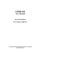
2.5 Product Dimensions
88 mm
300 mm
213 mm
9
2.6 Power Requirements
The model 4033 and 4034 can be operated from any source of 100-240V +/-10% AC, at a frequency from 48Hz to
66Hz. The maximum power consumption is 50 VA.
WARNING
THE LINE POWER VOLTAGE OF THE INSTRUMENT IS NOTED ON THE AC INPUT PLUG. TO
PREVENT DAMAGE TO THE INSTRUMENT, CHECK FOR PROPER MATCH OF LINE VOLTAGE
AND PROPER FUSE TYPE AND RATING.
The instrument power fuse is located in the AC input plug. To access the fuse, first disconnect the power cord and
then remove the fuse cartridge. Use T1A 250V fuse only, as labeled in the rear panel of the unit.
2.7 Grounding Requirements
For the safety of operating personnel, the instrument must be grounded. The central pin on the AC plug grounds the
instrument when properly connected to the ground wire and plugged into proper receptacle. The power jack and the
mating plug of the supplied power cable meet IEC safety standards.
WARNING
TO AVOID PERSONAL INJURY DUE TO SHOCK, THE THIRD WIRE EARTH GROUND MUST BE
CONTINUOUS TO THE POWER OUTLET. BEFORE CONNECTION TO THE POWER OUTLET,
EXAMINE ALL CABLES AND CONNECTIONS BETWEEN THE UNIT AND THE FACILITY POWER
FOR A CONTINUOUS EARTH GROUND PATH.
THE POWER CABLE MUST MEET IEC SAFETY STANDARDS.
2.8 Signal Connections
Use RG58U 50 Ω or equivalent coaxial cables for all input and output signals to and from the instrument. Below
specifies the BNC connectors on the instrument:
OUTPUT – Up to 10 Vpp into 50 Ω impedance (20 Vpp into open circuit). The instrument is protected from short
circuit to ground.
TRIG IN – 10 kΩ impedance, selectable positive or negative slope, variable level from – 10 V to + 10 V. Input
protected to ±15 V.
SYNC OUT – A positive pulse signal in phase with the main output. TTL levels with a 50 Ω source impedance and
with 3.5 ns typical transition times.
10
2.8.1 Maintaining Pulse Fidelity
Due to the extremely fast pulse rise times obtained from the instrument, special consideration must be given to
preserve pulse fidelity. Even at low repetition rates, high frequency components are present in the output waveform.
Use high quality coaxial cables, attenuators and terminations.
Note: RG 58 type coaxial cable and typical BNC connectors exhibit impedance tolerances which may cause visible
reflections. For maximum fidelity, use short, high quality, 50 Ω coaxial cables.
When signal comparison measurements or time difference determinations are made, the two signals from the test
device should travel through coaxial cables with identical loss and time delay characteristics.
When making connections that are not in a 50 Ω environment, keep all lead lengths short, 1/4 inch or less.
2.8.2 Impedance Matching
A mismatch, or different impedance in a transmission line, generates a reflection back along the line to the source.
The amplitude and polarity of the reflection are determined by the load impedance in relation to the characteristic
impedance of the cable. If the load impedance is higher than the characteristic impedance of the line, the reflection
will be of the same polarity as the applied signal. If it is lower, the reflection will be of opposite polarity. These
reflections add or subtract from the amplitude of the incident pulse causing distortion and irregular pulse shapes.
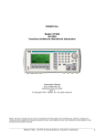
Impedance-matching network that provides minimum attenuation
A simple resistive minimum attenuation impedance matching network that can be used to match the instrument
output into relatively low impedance is shown in the above figure. To match impedance with the illustrated network,
the following conditions must exist:
(R1 + Z 2)R 2
= Z1
R1 + Z 2 + R 2
and
R1 +
R1 + Z 1R 2
Z1 + R 2
Therefore:
11
R1 R2 = Z1 Z2, and R1 Z1 = R2 (Z2-Z1)
or
R1 = Z 2(Z 2 − Z 1)
and
R 2 = Z1
Z2
Z 2 − Z1
For example: to match a 50Ω system to a 125Ω system, Z1 equals 50Ω and Z2 equals 125Ω
Therefore:
R1 = 125(125 − 50) = 96.8 Ω
and
R2 = 50
125
= 64.6 Ω
125 − 50
Although the illustrated network provides minimum attenuation, for a purely resistive impedance-matching device,
the attenuation as seen from one end does not equal that seen from the other end. A signal (E1) applied from the
lower impedance source, encounters a voltage attenuation (A1) which is greater than 1 and less than 2, as follows:
A1 =
E1 R1
=
+1
E2 Z2
A signal (E2) applied from the higher impedance source (Z2) encounters a greater voltage attenuation (A2), which is
greater than 1 and less than 2 (Z2/Z1):
A2 =
E 2 R1 R1
=
+
+1
E1 R 2 Z 1
In the example of matching 50Ω to 125Ω,
A1 =
96.8
+ 1 = 1.77
125
and
A2 =
96.8 96.8
+
+ 1 = 4.43
64.6 50
12
The illustrated network can be modified to provide different attenuation ratios by adding another resistor (less than
R1) between Z1 and the junction of R1 and R2.
When constructing such a device, the environment surrounding the components should also be designed to provide
smooth transition between the impedances. Acceptable performance can be obtained with discrete components using
short lead lengths; however, a full coaxial environment is preferred.
The characteristic impedance of a coaxial device is determined by the ratio between the outside diameter of the inner
conductor to the inside diameter of the outer conductor expressed as:
Z0 =
138
ε
log 10
D
d
2.8.3 Rise Time Measurements in Linear Systems
Consider the rise time and fall time of associated equipment when measuring the rise time or fall
time of a linear device. If the rise time of the device under test is at least ten times slower than
the combined rise times of the instrument, the monitoring oscilloscope, and associated cables, the
error introduced will not exceed 1%, and usually may be ignored. If the rise time or fall time of
the test device is less than ten times slower than the combined rise times of the testing system,
determine the actual rise time of the device under test by using the following formula:
Rt = (Rt 1) 2 + (Rt 2 ) 2 + (Rt 3) 2 + ......
Rt equals the overall rise time or fall time of the entire measurement system and R1, R2, R3, etc.
are the rise times or fall times of the individual components in the system.
2.9 RS-232 Connection
The rear panel RS-232 connector is a standard DB-9 male connector configured as a DCE. The pin assignments
are defined in the table below:
DB-9 pin Name
Note
13
1
2
3
4
5
6
7
8
9
TXD
RXD
GND
RTS
CRS
-
Transmit Data
Receive Data
Signal ground
Request to Send
Clear to send
-
*Note: Use a Null-modem or cross over cable (pin 2 and 3 switched) in order to communicate with instrument.
2.10 RS-232 Configuration
The instrument use 8 data bits, 1 stop bit, no parity and baud rate selectable from 2400 to 115K (2400, 4800,
9600, 19200, 38400, 57600, 115200). By default, the instrument is set at 19200-8-N-1.
Note: If 115K baudrate speed is used, ensure that the RS232 cable is short and can support this speed. Otherwise,
there may be some instability and intermittent data transmission failure between the interfacing computer and
the instrument.
2.11 GPIB Address
The address can be changed from the front panel by using the "UTILITY" menu.
2.12 GPIB Connections
The rear panel GPIB connector is an AMPHENOL 57-10240 or equivalent, and connects to a standard IEEE-488
bus cable connector. The GPIB line screens are not isolated from chassis and signal ground.
14
Section 3
Operating Instructions
3.1 General Description
This section describes the displays, controls and connectors of the Model 4033 and 4034 - Pulse Generators.
All controls for the instrument local operation are located on the front panel. The connectors are located on both
front and rear panels.
4
5
6
2
7
8
9
1
15
10
16
(Model 4034 only) 14
11
3
12
13
(Model 4033)
Figure 3.1 - Front Panel View
1.
2.
3.
4.
Power ON-OFF
Display Window
FI-F5 Keys
Menu Keys
- Applies and removes AC power to the unit
- Displays all instrument data and settings on a LCD.
- Select the menu options that appear on the bottom section of the LCD display.
- Select menu options for waveform parameters (PARAM), output levels
(OUTPUT), pulse edges (PULSE), triggering modes (MODE), setup
15
5.
6.
7.
8.
9.
10.
11.
12.
13.
14.
15.
16.
configurations (SETUP), and utility options (UTIL).
Numerical Keypad - Numeric entry keys for entering values for various functions and modes
Unit Setting Keys
- Quick keys for setting units for frequency, time, and amplitude
Rotary Knob
- Used to increment/decrement numerical values or to scan through the possible
selections.
Cursor Keys
- Used to move the cursor (when visible) to either left or right when modifying
values of various parameters.
Output ON
- Controls the main output signal. In model 4033, the output status is ON when
display shows “Out On” and the button lights up. In Model 4034, display will
show “On” next to “ch1” and/or “ch2” indicators depending on which channel is
selected to be on.
Channel Output
- (model 4034) Dual BNC independent channel outputs (50 Ω) of pulse signal.
Output ON
- (model 4033) Controls the main output signal. The output status is ON when
illuminated.
Channel Output
- (model 4033) BNC channel output (50 Ω).
Sync Out
- (model 4033) Sync output, 50 Ω 5V TTL level. Sync out for dual channel model
4034 is located in the rear panel of the instrument.
CHAN Key
- (model 4034 only) Channel select key
MAN TRIG Key
- Sends manual trigger pulse when pushed (requires instrument to be in manual
trigger mode)
ENTER Key
- Used for confirming parameter adjustments and settings.
3.2 Display Window
The pulse generator has a graphical LCD display that can display up to 160 x 80 dots. When you power-on the unit a
parameter (Frequency) and its current settings appear in the display. The bottom displays a menu that corresponds to the
function, parameter or mode display selected.
2
1
7
6
3
5
4
Figure 3.2 - LCD Display Screen
1.
2.
Channel/Output Display
Displays the current selected channel (when highlighted). (For model 4034 only). Also displays
highlighted text “Out On” when output is ON (For model 4033) or displays a highlighted text “On” next
to “Ch 1” and/or “Ch 2” when either or both channel outputs are ON (For model 4034).
General Waveform Display
16
Displays the general waveform being generated in the channel.
3.
4.
5.
6.
7.
Note: Waveform shown is approximated and scaled down. It does not show the exact representation of
the waveform at the output.
DEL Mode Display
Displays delay setting of the pulse. Alternatively, it can also display other parameters in other menu
items.
Menu Functions Display
Displays the menu options available. Use F1-F5 keys on front panel to select the options.
Secondary Parameter Display
Displays the values of parameters selected in the menu.
Depending on the options chosen, various parameters will display with a cursor for adjusting their values.
For example, width or duty cycle can be displayed.
Main Parameter Display
Displays the main parameter value. When highlighted, it can be adjusted with numeric keypad or rotary
knob. It can, for example, adjust frequency or period.
Mode Display
Displays the current mode of the generator. This can be the trigger mode of the power supply.
3.3 Front Panel Controls
The front-panel controls select, display, and change parameter, function, and mode settings. Use the rotary input knob
and the cursor movement keys to enter data into the pulse generator.
To change a setting:
1. Press the key that leads to a required item.
2. Move cursor using cursor keys to the appropriate position in the numeric field.
3. Use the rotary input or the numerical keyboard to change the value of the displayed item. Changes take effect
immediately.
The following subsections describe the function of each front panel key and connector.
3.4 Back Panel Controls
The pulse generator has 4 BNC Connectors on the rear panel where you can connect coaxial cables. These coaxial
connectors are labeled accordingly and serve as carrier lines for input and output signals delivered to and from the
pulse generator.
17
Model 4033
10
9
8
1
2
Model 4034
3
12
4
5
6
7
10
9
8
11
3
5
6
7
Figure 3.3 - Back Panel View
1.
2.
3.
4.
5.
Options 50 Ω - Reserved for future use.
Options TTL - Reserved for future use.
Trig In - Use this connector to apply an external trigger or gate signal, depending on the waveform
generator setting, to the generator. Maximum input is ± 15 V.
CTRL IN
- Not used
GPIB Interface - Use to interface with a computer via GPIB for remote communication.
18
6.
7.
8.
9.
10.
11.
12.
RS-232 Interface - This is a standard RS-232 port used for remote interface. Null modem or cross
serial cable is required to communicate with a PC via this port.
Earth GND - This screw is the earth ground that is tied to the chassis.
AC Power Connector - Used to connect power cable to AC line source.
Fuse Box
- Fuse compartment. For replacement, use T1A, 250V fuse only.
Cooling Fan - To ensure proper cooling, please leave room between the fan output and other objects
with at least one feet distance.
SYNC OUT - (Model 4034 only). 50 Ω TTL sync output for channel 1.
TRIG IN and SYNC OUT - (Model 4034 only). TRIG IN and SYNC OUT BNC connectors for
channel 2. SYNC OUT is a 50 Ω TTL level signal. TRIG IN accepts maximum ± 15 V.
3.5 Output connectors
The pulse generator output circuits operate as a 50 Ω voltage source working into a 50 Ω load. At higher frequencies,
un-terminated or improperly terminated output cause aberrations on the output waveform. In addition, loads less than
50 Ω reduce the waveform amplitude, while loads more than 50 Ω increase waveform amplitude.
Excessive distortion or aberrations caused by improper termination are less noticeable at lower frequencies.
To ensure pulse integrity, follow these precautions:
1. Use good quality 50 Ω coaxial cable and connectors.
2. Make all connections tight and as short as possible.
3. Use good quality attenuators if it is necessary to reduce pulse amplitudes applied to sensitive circuits.
4. Use termination or impedance-matching devices to avoid reflections.
5. Ensure that attenuators and terminations have adequate power handling capabilities.
If there is a DC voltage across the output load, use a coupling capacitor in series with the load. The time constant of
the coupling capacitor and load must be long enough to maintain pulse flatness.
Impedance Matching
If the waveform generator is driving a high impedance, such as the 1 MΩ input impedance (paralleled by a stated
capacitance) of an oscilloscope vertical input, connect the transmission line to a 50 Ω attenuator, a 50 Ω
termination and to the oscilloscope input. The attenuator isolates the input capacitance of the device and terminates
the waveform generator properly.
3.6 MENU Keys
These keys select the main menus for displaying or changing a parameter, function or mode. Below is the hierarchy
and selections of the menu tree.
MENU TREE
-
-
PARAM
o
o
o
o
o
OUTPUT
o
o
o
PERIOD | FREQ
WIDTH | DUTY
DELAY
INDEP | CH1 (When CH2 is selected only)
SINGLE | DOUBLE
HILVL
LOLVL
PREDEF
ECL
19
o
-
-
PULSE
o
o
o
o
MODE
o
o
o
o
-
-
o
SETUPS
o
o
o
UTIL
o
o
o
o
TTL
CMOS
USER
HIPRED | LOPRED
OUTPUT LIMITS
LIM OF
LIM ON
HILIM
LOLIM
PREV
RISE
FALL
EQUAL
NORM | COMPL
CONT
TRIG
GATE
BURST
EXTWID
MAN (Manual Trigger)
INT (Internal Trigger Rate)
EXT (External Trigger)
PREV
MAN (Manual Gate Trigger)
INT (Internal Gate Trigger Rate)
EXT (External Gate Trigger)
PREV
MAN (Manual Burst)
INT (Internal Burst Rate)
EXT (Burst External)
NBRST (Number of Bursts)
PREV
RECALL
STORE
CLEAR ALL
GPIB (ACTIVE) (GPIB Address)
RS232 (ACTIVE) (Baudrate)
INTEN
POWER (Power On Setup)
3.6.1 PARAMETER Menu
This key selects and displays the waveform frequency, amplitude, offset and external reference and allows changing the
parameter data.
Frequency Menu
F1: PERIOD/FREQ
- Selects and displays the period or the pulse frequency. Change the values using the
cursor keys, rotary knob or numerical keys. If a certain setting can't produce the
waveform at the desired parameters, the generator displays an error message. While the
20
pulse mode is set to external width on, the value of the period may be changed but the
value is not displayed, since the actual value of the period is set by the external pulse
F2: WIDTH/DUTY
- Selects and displays the pulse width and duty cycle. The minimum value of the width
is 10ns, with the maximum value dependent on the values of the period, delay and
transition times. The Duty Cycle is defined as the ratio of the pulse width to the pulse
period. Changing the duty cycle will therefore change the width accordingly. The duty
cycle has both a value and a state (on or off). On Power On the duty cycle is off. This
means that the width is determined by the width parameter only. The duty cycle is set to
ON by entering a value. The value may then be changed using the rotary encoder or the
numeric keys. When the duty cycle is on, changing the period will cause a change in the
width such that the duty cycle is kept constant. The duty cycle is set to OFF by
changing the width value. The instrument will store the last value of the duty cycle, and
set the duty cycle to this value when it is next set to ON. The duty cycle has an absolute
range of 1 % to 99 %, but the actual value is limited by the values of the period, delay
and transition times.
F3: DELAY
- This parameter is used in two instances. The first is to set the delay of the pulse in the
single pulse mode. The delay governs the time from the SYNC signal to the start of the
pulse. The second instance is the double pulse mode. Here the delay governs the time
from the SYNC pulse to the beginning of the second pulse. The minimum and
maximum values of the delay are dependent on the values of the period, width and
leading and trailing edge times. The delay range is 0 to 9.80000 s.
Delay Menu
F4: INDEP/CH1
- When channel 2 is selected using the CHAN button, this menu option will appear. By
default, it is selected in INDEP, which makes channel 2 an independent channel. If
CH1 is selected, channel 2 and channel 1 will have matching clock and trigger. The
period and frequency will also be the same as channel 1. In this mode, all triggering
options will not be available in the MODE menu, as it will be dependent on channel 1
settings. Frequency and Period adjust options will also be disabled. Aside from these,
all other parameters are still adjustable.
F5: SINGLE/DOUBLE - The unit can be set to generate either a SINGLE pulse or a DOUBLE pulse. In the
double pulse mode, the first pulse is generated without delay from the start and the
second pulse in generated after a delay, from the start of the period, as determined by
the DELAY parameter. Thus, in order to generate a double pulse, the delay must first
be set, and then the double pulse may be set on. The double pulse mode state is toggled
using the F5 key. The minimum and maximum values of the delay are dependent on the
values of the period, width, delay and transition parameters.
21
Double Pulse
3.6.2 OUTPUT Menu
The Output menu enables the pulse high and low levels to be set. The levels are limited by four factors:
- The absolute limits are ±10 V.
- The high level must be greater than the low level.
- The pulse amplitude must be between 0.1 V and 10 V p-p, into 50 Ω.
- The levels cannot exceed the limits as set in the OUTPUT LIMITS menu.
Output Menu
F1: HILVL
- Selects the pulse high level voltage.
F2: LOLVL
F3: PREDEF
- Selects the pulse low level voltage.
- Selects predefined pulse output levels. In addition to being able to set the levels to any
value within the limits, the user may also select one of four pre-defined levels:
CMOS: Low level (LOLVL) = 0 V,High level (HILVL) = 5 V
TTL: Low level (LOLVL) = 0.4 V, High level (HILVL) = 2.4 V
ECL: Low level (LOLVL) = -1.8 V, High level (HILVL) = -0.8 V
USER: User-defined levels, entered by using the USER menu (F5: HIPRED and
LOPRED) Press OUTPUT to exit USER menu.
22
Predefined Output Menu
F5: OUTPUT LIMITS
- Allows entering limits for the output levels to protect external devices connected to
the unit output.
Output Limits Menu
F1: LIM OF – Turns off limit level protection
F2: LIM ON – Turns on limit level protection
F3: HILIM – Sets high limit for protection
F4: LOLIM – Sets low limit for proection
F5: PREV – Returns to previous menu level
3.6.3 PULSE Menu
Pulse Menu
F1: RISE
- Selects the pulse Rise time (Leading edge).
F2: FALL
- Selects the pulse Fall time (Trailing edge).
F3: EQUAL
- Selects equal Rise (Leading edge) and Fall (Trailing edge) times.
F5: NORMAL/COMPL - Selects Normal or Complement pulse mode.
23
Complement Pulse Mode
The transition time range is 5 ns to 100 ms, but the value is limited to a 20:1 ratio between the transition
times. In addition, both values must be within one of the following ranges:
5 ns – 100 ns
50 ns – 1 µs
500 ns – 10 µs
5 µs – 100 µs
50 µs – 1 ms
500 µs – 10 ms
5 ms – 100 ms
The transition times are also limited by the values of the period, width and delay.
24
3.6.4 MODE Menu
Selects the output trigger mode: CONT (Continuous), TRIG (Triggered), GATE (Gated), BRST (Burst) and
EXTWID (External pulse).
To select the output mode, press MODE, then press the function key that corresponds to the desired Mode menu
option, as shown:
Mode Menu
F1: CONT - (Continuous) - Selects continuous output.
F2: TRIG
- (Triggered) – Triggers one output cycle of the selected pulse for each trigger event.
F3: GATE - (Gated) - Triggers output cycles as long as the trigger source asserts the gate signal.
F4: BRST - (Burst) - Triggers output N output cycles for each trigger event, where N ranges from 2 to 999,999.
F5: EXTWID - In the external width (EXT WID) pulse mode, the pulse period and width are determined by the
externally applied signal. The pulse generator then applies transition and level parameters to this
signal in order to generate the pulse. The period, width and delay may be changed, but their change
has no effect on the pulse, and their values are not displayed. The trigger mode may not be changed
while the external width pulse mode is enabled.
External Pulse
25
After selecting the TRIG , GATE or BURST menu, the trigger source menu is available:
For TRIG and GATE mode:
Trigger Menu
F1: MAN - Selects manual as the trigger source. Pressing the MAN TRIG key generates the
trigger. In the Gate trigger mode, the pulse is generated as long as the key is being pressed.
F2: INT - Selects the internal trigger generator as the trigger source. Change the internal trigger
rate displayed with the rotary input knob or numerical keys. The rate has a range of 100 ns to
99.99 s, although the minimum value is limited by the value of the period in that the rate cannot be
less than the period.
Internal Trigger
F3: EXT - Selects the external trigger signal as the trigger source. The trigger source is supplied
through the TRIG IN connector.
F4: LEVEL/SLOPE - Two parameters are related to external trigger source operation.
These are LEVEL and SLOPE. The Level determines at what voltage level the external
signal will be recognized as a trigger. At level less than this, no pulse will be generated.
The Slope determines whether the positive or negative edge of the trigger signal will
trigger the pulse. Use the rotary knob to toggle between the two selections.
For Burst Mode:
F1: MAN - Selects manual as the trigger source. Pressing the MAN TRIG key generates the
trigger. In the Gate trigger mode, the pulse is generated as long as the key is being pressed.
F2: INT - Selects the internal trigger generator as the trigger source. Change the internal trigger
rate displayed with the rotary input knob or numerical keys. The rate has a range of 100 ns to
26
99.99 s, although the minimum value is limited by the value of the period in that the rate cannot be
less than the period.
F3: EXT - Selects the external trigger signal as the trigger source. The trigger source is supplied
through the TRIG IN connector.
F4: NBRST
- Selects the number of burst cycles to burst. Set from 2 to 999,999 cycles.
F5: LEVEL/SLOPE - Two parameters are related to external trigger source operation. These are
LEVEL and SLOPE. The Level determines at what voltage level the external signal will be
recognized as a trigger. At level less than this, no pulse will be generated. The Slope determines
whether the positive or negative edge of the trigger signal will trigger the pulse. Use the rotary
knob to toggle between the two selections.
3.6.5 SETUPS Menu
The pulse generator can store the current front-panel settings and recall them into one of 99 storage buffers. When
you recall a setup, the pulse generator restores the front-panel settings to those that you stored in the selected
buffer. Because it is impossible to 100% guarantee against loss of stored data, you should maintain a record of the
data stored in memory so that you can manually restore such data, if necessary.
Setups Menu
F1: RECALL
- Recalls a previously stored front-panel setup from the selected buffer. Change the
buffer number by using the rotary input knob. Valid storage buffer numbers are from 1
to 99.
Buffer 0 is the factory default setup; buffer 100 is the last front panel setup before
power-off.
F2: STORE
- Stores the current front-panel setup to the specified storage buffer. Change the buffer
number by using the data keys or the rotary input knob. Valid storage buffer numbers
range from 1 to 99.
F4: CLEAR ALL
- Clears all data on all memory settings, after a YES or NO selection message.
27
3.6.6 UTILITY Menu
Utility Menu
F1: GPIB
-Selects the GPIB remote mode of operation. After selection the GPIB address can be set to any
value from 1 to 31 using the rotary knob. The value is kept in a nonvolatile memory and used at
power-on. The factory default address is 10. Setting the address to 31 puts the device in the offbus state (it will not respond to messages on the GPIB bus).
GPIB Menu
F2: RS232
-Selects the RS232 remote control mode. After selection, the baud rate can be selected as 1200,
2400, 9600, 19200, 38400, 57600 or 115K. Always the RS-232 uses 8 bit data, 1 stop bit and no
parity.
Note: If 115K baudrate speed is used, ensure that the RS232 cable is short and can support this
speed. Otherwise, there may be some instability and intermittent data transmission failure
between the interfacing computer and the instrument.
F3: INTEN
- Selects the intensity of the LCD display. Select a value using the rotary input knob. Valid
numeric values are from 1 to 31. The value is kept in the nonvolatile memory, after a 20 seconds
28
time-out.
F4: POWER
- (Power-on default) Selects the power-on default setting. Select a value using the data keys or
the rotary input knob. The selection is effective after a 20s time-out period. Select zero (0) to
have the pulse generator power on with the factory default settings. Select 99 to have the pulse
generator power-on with the settings it had at the last power-off. Select any other value in the
range from 1 to 98 to have the pulse generator power-on with the settings that you have saved
with SETUPS STORE in the range 1 to 99.
Power-On Menu
NOTE: Power-on settings cannot restore the status of output at power-on, meaning if the
output is ON, power-on settings cannot recall it to be ON at start up. This setting will always
remain OFF and power on, which is same as the default setup indicated above in Table 3-2.
Although the output status can be stored into memory for recall using the store/recall functions,
it cannot be recalled for a power-on setting start up. This is due to safety concerns as sensitive
devices that are connected to the outputs of the generator may accidentally be damaged at
power-on if the power-on configurations are not set properly (i.e. Amplitude level set too high
for power-on may easily damage a sensitive device by accident).
3.7 ON Key
Use this key to control the main output signal. A build-in LED lights when the output is active.
3.8 Cursor Movement Keys
Use these keys to move the cursor (when visible) either left or right. They are used in conjunction with the rotary
input knob to set the step size of the rotary input knob.
3.9 Rotary Input Knob
Use this knob to increase and decrease numeric values or to scroll through a list. The cursor indicates the low-order
position of the displayed value which changes when you rotate the knob (for straight numeric entries only). For other
types of data, the whole value changes when you rotate the knob.
3.10 Power-On Settings
29
At power-on, the pulse generator performs a diagnostic self-test procedure to check itself for errors. When the pulse
generator finishes the diagnostic self-test routine, it enters the local state (LOGS) and assumes power-on default
settings if the POWER-ON setting is at 0. You can program the pulse generator for any settings you want at power
on, as described earlier in this section.
The factory default settings are:
Power-on Default Settings
Key Functions
PERIOD
WIDTH
DELAY
DPDELAY
Values
500 ns
200 ns
0 ns
5 us
HILVL
LOLVL
MODE
N-BURST
SLOPE
TLVL
TRIG SOURCE
INT TRG RATE
OUPTUT
PULSE MODE
2.5 V
-2.5 V
CONT
2
POS
1V
MAN
1 ms
OFF
Normal
MODULATION
RISE
FALL
OFF
5 ns
5 ns
Table 3-2
Comments
Pulse Period
Pulse Width
Pulse delay from Sync out
Delay between pulses in double
pulse mode
Pulse high level
Pulse low level
Pulse mode
Waves per burst
Positive external trigger slope
External trigger level
Trigger source
Internal trigger rate
Output disabled
Normal single pulse
output
Modulation execution
Pulse rise time
Pulse fall time
NOTE: Power-on settings cannot restore the status of output at power-on, meaning if the output is ON, power-on settings
cannot recall it to be ON at start up. This setting will always remain OFF and power on, which is same as the default setup
indicated above in Table 3-2. Although the output status can be stored into memory for recall using the store/recall
functions, it cannot be recalled for a power-on setting start up. This is due to safety concerns as sensitive devices that are
connected to the outputs of the generator may accidentally be damaged at power-on if the power-on configurations are not
set properly (i.e. Amplitude level set too high for power-on may easily damage a sensitive device by accident).
3.11 Memory
The pulse generator uses a non-volatile FLASH memory for storing front panel settings. Up to 100 front panel
settings can be stored.
3.12 Displaying Errors
At power-on, the waveform generator performs a diagnostic routine to check itself for problems. If the diagnostic
routine finds an error, an error message is displayed. The waveform generator also displays error messages when
front-panel settings are either invalid or may produce unexpected results.
30
Error messages
Message Text
Setting conflict
Trig rate short
Empty location
Calibration Error
LCA load error
Output overload
Verify unit calibration
Incorrect entry
Width too high
Set other level
Save to Flash failed
Out of range
Cause
Can't have this parameter set with other parameters.
Internal trigger rate too short for pulse or burst.
Attempt to restore a non existent setting.
An error when performing unit calibration – for service personnel only.
Internal hardware error, must re-power the unit
An excessive loading of the output stage
At power-on the unit checks for valid calibration data. Need to calibrate the unit.
A incorrect value entry or syntax error
The width value is too high for the pulse period selected
When the pulse amplitude is >10Vp-p, need to change the other pulse level
When saving the instrument settings. Need to save again the setting.
Attempt to set a value out of instrument limits or in conflict with other pulse
parameters.
3.13 Pulse Definitions
The figures illustrate the various pulse parameter definitions.
Pulse HIGH LEVEL corresponds to the most positive level of the pulse. Pulse LOW LEVEL corresponds to the
most negative level of the pulse. Pulse AMPLITUDE is defined as the difference between the HIGH LEVEL and
LOW LEVEL values.
Transition time (LEADING or TRAILING EDGE) is the interval required for the pulse to go from 10% to 90% of
the selected amplitude or vice versa.
The way in which the instrument defines pulse parameters makes a distinction between the selected pulse, which
assumes the fastest transition times and the actual pulse output. The values specified for WIDTH, PERIOD, and
DELAY are defined with reference to the point at which the selected pulse reaches 50% of the amplitude during the
leading and trailing edges at the fastest transition time.
WIDTH is the time interval between the 50% points of the leading and trailing edges. If the selected leading and
trailing edge transition times are equal, the time interval between the 50% points is the same as that between the first
and third corners.
PERIOD is the time between the 50% points on the rising edges of two consecutive trigger outputs. DELAY is the
time between the 50% points on the rising edge of the TRIG OUTPUT pulse and the 50% point of the leading edge
of the output pulse (at fastest transition time).
When VARIABLE TRANSITION TIMES are selected, the time interval between the 50% points of the actual
pulse depends on both the WIDTH and TRANSITION TIME settings. A trailing edge slower or faster than the
leading edge respectively lengthens or shortens the 50% interval. In effect, the pulse edges pivot about the first and
third corners while the interval between these corners remains fixed for a given width setting.
As long as the leading and trailing edge times are equal, the selected width and the actual width are the same.
31
In the SINGLE or DOUBLE pulse mode the instrument defines PERIOD as the time between the 50% points on
the leading edges of two consecutive trigger outputs. DELAY, in double pulse mode, is the time between the leading
edges of the first and second pulse using as a reference point 50% amplitude with fastest transition times.
SETTLING TIME is the interval required for the pulse level to enter and remain in the specified level ACCURACY
RANGE, measured from the 90% AMPLITUDE point.
3.14 Pulse Parameter Limitations
The following formulas express the limits on Period, Width, and Delay.
Single Pulse per Period Modes
(Un-delayed, Delayed, Counted Burst with single pulse mode)
[Period - (Width + Delay)] must be > 10 ns
0.99 * Period must be > (Width + Delay)
Pulse max
Pulse min
Width max
Width min
Delay max
Delay min
= 10.00 s
= (Width + Delay + 10 ns), but not less than 20 ns
= [(Period * 0.99) - Delay – 10 ns], but not more than 9.89999 s
= 10 ns
= [(Period * 0.99) - Width – 10 ns], but not more than 9.89998 s
=0
Single Pulse Transition Time Restrictions
Width must be > 1.3 * Leading Edge
(Period - Width) must be > 1.3 * Trailing Edge
Double Pulse per Period Modes
(Paired Pulse and Counted Burst with Paired pulses)
Delay must be > Width
0.99 * Delay must be > (Width + 10 ns)
Pulse max
Pulse min
Width max
Width min
Delay max
= 10.00 s
= (Width + Delay + 10 ns), but not less than 40 ns
= [(0.99 * Delay) – 10 ns], but not > 4.85000 s
= 10 ns
= [(Period * 0.99) - Width –10 ns], but not > 9.80000 s
32
Delay min
= (Width + 10 ns)
Double Pulse Transition Time Restrictions
Width must be > 1.3 * Leading Edge
(Delay - Width) must be > 1.3 * Trailing Edge
[Period - (Delay + Width)] must be > (1.3 * Trailing Edge)
Internal Trigger Burst Mode
(0.99 * Trig Rate) must be > (Period * Burst Count)
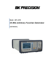
3.15 Pulse Definitions
TRIG OUTPUT
50%
3rd Corner
HIGH LEVEL
-----------------
1st Corner
LEADING
EDGE
90%
50%
------
10%
------
LOW LEVEL
WIDTH
-----------------
AMPLITUDE 50%
-----------------
90%
10%
TRAILING
EDGE
Pulse Definitions – High and Low Levels
33
TRIG OUTPUT
FASTEST TRANSITION
TIMES SELECTED
WIDTH
50%
ACTUAL
DELAY
VARIABLE TRANSITION
TIMES SELECTED
1st Corner
-------------------------------
DELAY
50%
50%
3rd Corner
----------------------------------
PERIOD
-------------------------------
----------------------------
50%
Pulse Definitions – Width, Period, and Delay
50%
50%
50%
WIDTH
50%
3rd Corner
50%
50%
-------------------------------
1st Corner
DELAY
WIDTH
-------------------------------
VARIABLE TRANSITION
TIMES SELECTED
-------------------------------
FASTEST TRANSITION
TIMES SELECTED
PERIOD
50%
3rd Corner
------------------------------------
TRIG OUTPUT
Pulse Definitions – Period and delay – Double Pulse Mode
34
----------------------------
----------------------------
ACCURACY
RANGE
------------------------------------------------------90% AMPLITUDE
SETTLING TIME
10% AMPLITUDE
Pulse Definitions – Settling Time
Section 4
Programming
4.1 Overview
4.1.1 GPIB
This section provides detailed information on programming the pulse generator via the IEEE 488 bus (GPIB General Purpose Interface Bus). The pulse generator is programmable over the IEEE 488 bus, and its message
protocol is compatible with IEEE 488.2. The device command set is compatible with the SCPI 1992.0 standard.
The SCPI standard does not cover all the needs of the pulse generator, and so the standard has been added where
necessary.
The command syntax as defined by the IEEE 488.2 and SCPI standards is briefly explained in the following
sections. Users who have experience programming GPIB instruments may skip these paragraphs, and go directly
to where the individual command syntax is given. Users wishing to gain further insight should consult the
standards.
4.1.2 RS-232-C
Be sure that you have the Remote Mode set to RS-232 and correctly set the baud rate.
35
EIA standard RS-232-C specifies the electrical characteristics and pin out of a serial communication standard for
connecting "data terminal equipment" (DTE) to "data communication equipment" (DCE). Data terminal equipment
is usually devices such as terminals, computers, or printers that are the final destination for data. Data
communication equipment, on the other hand, is usually a modem or other device that converts the data to another
form and passes it through. The instrument can be configured only as a DCE, so in most cases it can be connected
with a straight-through cable to a computer, but would require special cabling to connect to another DCE device.
The baud rate is the bit rate during the transmission of a word in bits per second. Different devices use many baud
rates, but the baud rates of the two devices that are connected must be the same.
Data signals over the RS-232-C use a voltage of +3V to +25V to represent a zero (called a space) and a voltage of 3V to -25V to represent a one (called a mark). Handshake and control lines use +3V to +25V to indicate a true
condition and -3V to -25V to indicate a false condition.
When no data is being transmitted, the idle state of the data lines will be the mark state. To transmit a byte, the
transmitting device first sends a start bit to synchronize the receiver.
The RS-232-C standard is not very specific about many of the handshaking signals and it is therefore usually
necessary to refer to the manuals for both of the devices being connected to determine the exact pin out, signal
definition, and signal direction for the devices.
The serial interface implements the same SCPI command set as the GPIB interface. The instrument is
programmed by sending ASCII coded characters to the instrument.
When the instrument is in the remote mode, remote command input has priority over any front panel control.
Therefore, as long as the serial interface is continuously supplied with data, the keyboard will appear to be
inoperative to the user.
Note: In remote mode, any command sent or received via RS232 will change the display screen with the
following:
User can return to local control with the press of any front panel keys, but it is extremely important to note that
this should be done ONLY when nothing is being sent or transferred between the instrument and the connected
PC. Any interruptions during transfer may delay the communication process or cause communication errors.
The instrument accepts a line feed (LF) as an end of string (EOS) terminator.
4.2 Device State
The device may be in one of the four possible states described below. The transition between states is defined by
IEEE 488.1.
4.2.1 Local State (LOCS)
36
In the LOCS the device may be operated from the front panel only. Its settings may be queried over the GPIB, but
not changed. Commands that do not affect the signal being output by the instrument are accepted.
4.2.2 Local With Lockout State (LWLS)
In the LWLS the device may be operated from the front panel only. Its settings may be queried over the GPIB, but
not changed. Commands that do not affect the signal being output by the instrument are accepted. The difference
between the LOCS and the LWLS is that from the LWLS the device may enter the Remote With Lockout State.
4.2.3 Remote State (REMS)
In the REMS the device may be operated from the GPIB. Actuating any front panel key will cause the device state
to revert to the LOCS.
4.2.4 Remote With Lockout State (RWLS)
In the RWLS the device is operable only from the GPIB. Front panel operation may be returned by either sending
an appropriate IEEE 488.1 command, or by cycling the device power.
4.3 Interface Function Subsets
The following interface function subsets are implemented in the pulse generator:
SH1, AH1, T6, L4, SR1, RL1, PP0, DC1, DT1, E2, C0
4.4 Device Address
The GPIB address of the device may be set to any value from 0 to 31. The address may be changed from the front
panel, using the numeric keypad or the rotary encoder, or via the GPIB itself using the command:
:SYSTem:COMMunicate:GPIB:ADDRess
Setting the device to address 31 puts it in the 'off-bus' state. In this state it will not respond to messages on the
GPIB. If the device is in the REMS when set to address 31, an internal 'return-to-local' command will be given,
setting the device to the LOCS. If the device is in the RWLS, the 'return-to-local' command is ignored, and the
device remains in the RWLS. The only way to then re-establish communication with the device over the GPIB is
to cycle the power, and to then change the address to that required from the front panel.
4.5 Message Exchange Protocol
The device decodes messages using the Message Exchange Protocol (MEP) defined in IEEE 488.2. The following
functions implemented in the MEP must be considered:
4.5.1 The Input Buffer
37
The device has a 128-byte long cyclic input buffer. Decoding of remote messages begins as soon as the input
buffer is not empty, that is, as soon as the controller has sent at least one byte to the device. Should the input
buffer be filled up by the controller faster than the device can remove the bytes and decode them, the bus
handshake is not completed until room has been made for more bytes in the buffer. This prevents a fast controller
from overrunning the device with data.
If the user has sent part of a Program Message, but not the Program Message Terminator, and wishes to abort the
message decoding and execution, the Device Clear command may be sent, or front panel operation resumed (in
REMS only).
4.5.2 The Output Queue
The device has a 100-byte long output queue in which it stores response messages for the controller to read. If at
the time a response message is formatted the queue contains previously formatted response messages, such that
there are not enough places in the queue for the new message, the device will put off putting the message in the
queue until there is place for it.
The Status Byte MAV bit, when set, indicates that part or all of a response message is ready to be read.
4.5.3 Response Messages
The device sends a Response Message in response to a valid query. All queries return a single Response Message
Unit, and all query responses are generated at the time the query is parsed.
4.5.4 Coupled Commands
Coupled Commands are either commands whose execution validity depends on the value of other parameters, or
commands whose execution changes the value of another parameter. The execution of commands designated as
being coupled is deferred until all other commands in the same Program Message have been executed. The
coupled commands are then grouped together according to their functionality, and executed as a group. All
parameters of the pulse generator are coupled.
4.6 Instrument Identification
The *IDN? common query is used to read the instrument's identification string. The string returned is something
similar to the following:
B&K, MODEL 4034,0,V0.40
4.7 Instrument Reset
The *RST common command effects an instrument reset to the factory default power up state.
4.8 Self Test
The *TST common query causes the device to perform a self test. This self test consists of checking the functionality
of the pulse generator.
38
4.9 Command Syntax
4.9.1 General Command Structure
The device commands are generally defined by the SCPI standard, with the exception of those
instrument functions for which SCPI commands do not as yet exist.
The Common Commands and Queries are defined by IEEE 488.2. The command syntax, i.e. how a
command is structured, is defined by IEEE 488.2.
4.9.2 The Program Message
A Program Message is defined as a string containing one or more Program Message Units, each of
which is an instrument command or query. Program Message Units are separated from each other by
the Program Message Unit Separator. The Program Message is terminated by the Program Message
Terminator.
The Program Message Unit Separator consists of a semicolon (';'), optionally preceded and/or followed
by white-space characters. A white-space character is defined as the ASCII characters in the ranges
00H-09H, and 0BH-20H. This range includes the ASCII control characters and the space, but excludes
the Linefeed character.
The Program Message Terminator consists of optional white-space characters, followed by one of three
options:
-
Linefeed (LF) character (ASCII 0A);
-
GPIB EOI bus line being set true on the last byte of the message;
- LF being sent with EOI true.
The Program Message Unit can be divided into three sections as follows.
4.9.2.1 Program Message Header
The Program Header represents the operation to be performed, and consists of ASCII character
mnemonics. Two types of Program Headers are used in the pulse generator: Instrument-control headers
and Common Command and Query headers. A Program Header may consist of more than one
mnemonic, in which case the mnemonics are separated from each other by the colon (':'). For
instrument control commands, the mnemonics are specified by the SCPI standard, and indicate the tree
structure of the command set. The first mnemonic indicates the subsystem being controlled. Common
Command and Query Program Headers consist of a single mnemonic prefixed by an asterisk ('*').
The mnemonics consist of upper- or lower-case alpha characters. Mnemonics may be written in either
the long form, in which the entire mnemonic is written out, or the short form, in which only a specified
portion of the mnemonic is written out. Some mnemonics have only one form due to their short length.
Where a command is described, the portion appearing in upper case is the short form. Only the short
form or the long form may be used.
Example: The command to set the period to 1 microsecond may be written in the following ways:
SOURCE:PULSE:PERIOD 1US
SOUR:PULS:PER 1US
SOURCE:PULSE:PERIOD 1US
Some mnemonics in a specified Program Header may be optional. This is indicated in the command
description by the mnemonic being enclosed in square brackets ([...]).
This means it is not necessary to write the mnemonic into the Program Header: it is a default condition.
The 'SOURCE' mnemonic, for example, is optional. Not specifying it will cause the device to search
for the mnemonics in the Program Header under the Source Subsystem. For example, the period may
be set by the command:
:PULS:PER 1US
39
4.9.2.2 Program Message Header Separator
The Program Header Separator is used to separate the program header from the program data. It
consists of one or more white-space characters, denoted as <ws>. Typically, it is a space.
4.9.2.3 Program Message Data
The Program Data represent the values of the parameters being set, for example, the '1US' in the above
examples. Different forms of program data are accepted, depending on the command. The Program
Data types used in the pulse generator are as follows:
1.
Character program data – This form of data is comprised of a mnemonic made up of lower - or
upper-case alpha characters. As with Program Header mnemonics, some Character Data
mnemonics have short and long forms. Only the short or the long form may be used.
2.
Boolean data – Boolean data indicate that the parameter can take one of two states, ON or OFF.
The parameter may be character type ON or OFF or numeric. A numeric value is rounded to an
integer. A non-zero result is interpreted as 1 (ON), and a zero result as 0 (OFF). Queries return
the values 0 or 1.
3.
NRf – This is a decimal numeric data type, where
NR1 indicates an integer number,
NR2 indicates a fixed-point real number, and
NR3 indicates a floating-point real number.
All parameters that have associated units accept a suffix, which may be specified using upper or lower-case characters. When the suffix is not specified, the numeric value is accepted in the
default units, which are Hertz for frequency, Seconds for time, and Volts for voltage. To set the
period to 1 microsecond we can send one of the following commands:
:PULS:PER 1E-6 or :PULS:PER 1000NS
The special forms of character data accepted as numbers as defined by SCPI are NOT accepted
by the pulse generator.
There are two types of Program Message Units: Command Message Units and Query Message
Units. A Query differs from a Command in that the Program Header is terminated with a
question mark ('?'). For example, the period might be queried with the following query:
:PULS:PER?
Not all Program Message units have query forms, such as STATUS:PRESET, and some
Program Message Units might have only the query form, such as SYSTEM:VERSION?. The
pulse generator puts the response to the query into the output queue, from where it may be read
by the controller. The Status Byte MAV bit is set to indicate to the controller that a response is
ready to be read.
4.9.3 SCPI Command Structure
SCPI commands are based on a hierarchical structure. This allows the same instrument-control
header to be used several times for different purposes, providing that the mnemonic occurs in a unique
position in the hierarchy. Each level in the hierarchy is defined as a node. Mnemonics in the different
levels are separated from each other by a colon (':'). The first Program Message Unit, or command, in a
Program Message is always referenced to the root node. Subsequent commands are referenced to the
same level as the previous command.
A Program Message Unit having a colon as its first character causes the reference to return to the root.
This process is defined by IEEE 488, section A.1.1. Consider the following examples:
1.
The following command may be used to set the high and low levels of the pulse. Note that the
LOW command is referenced to the command preceding it. The LOW mnemonic resides at the
same node as the HIGH command.
SOURCE:VOLTAGE:HIGH 5V;LOW 2V
40
2.
This command sets the frequency and the high level. The FREQUENCY and VOLTAGE
mnemonics are at the same level.
SOURCE:FREQUENCY 2KHZ;VOLTAGE:HIGH 4V
3.
When Program Message Units describe different subsystems, a colon prefix must be used to
reset the command reference to the root. Here the frequency and the output state are set.
SOURCE:FREQUENCY 3KHZ;:OUTPUT:STATE ON
Common Commands may be inserted in the Program Message without affecting the instrumentcontrol command reference. For example,
SOURCE:VOLTAGE:HIGH 4V;*ESE 255;LOW 2V
4.10 Status Reporting
The instrument is capable of reporting status events and errors to the controller, using the IEEE 488.1
Service Request function and the IEEE 488.2 Status Reporting structure.
4.10.1 The Status Byte
Status summary information is communicated from the device to the controller using the Status Byte
(STB). The STB is composed of single-bit summary-messages, each summary message summarizing
an overlying Status Data Structure. By examining the content of the STB, the controller gains some
information concerning the instrument's status. The STB bits are defined as follows:
Bit 0: Unused
Bit 1: Unused
Bit 2: Error/event queue summary message (EVQ). This bit is set if the queue is not empty.
Bit 3: Questionable Status summary message. This bit is not used by the pulse generator.
Bit 4: Message Available (MAV) summary message. This bit is set whenever all or part of a
message is available for the controller to read. The controller may be ready to read the
response message before it is available, in which case it can either wait until this bit is
set, or it can start to read. In the second case, the controller time-out must be set so that
the read action will not be aborted before the message has been read.
Bit 5: Event Status Bit (ESB) summary message. This bit is set to indicate that one or more of
the enabled standard events have occurred.
Bit 6: Request Service (RQS). This bit is set when the device is actively requesting service.
Bit 7: Operation Status summary message. No Operation Status events are defined in the pulse
generator, and so this bit is never set.
The STB is read by the controller during a serial poll. If the RQS bit was set, it is then cleared. The
STB may also be read by the *STB? common query.
4.10.2 Service Request Enabling
Service request enabling allows the user to select which Status Byte summary messages may cause the
device to actively request service. This is achieved using the Service Request Enable Register, which
is an 8-bit register whose bits correspond to those of the STB. The RQS bit in the STB is set when a bit
in the STB is set, and its corresponding bit in the service request enable register is set.
The service request enable register is set using the *SRE common command, and read using the *SRE?
common query.
41
4.10.3 Standard Event Status Register
The Standard Event Status Register (SESR) is defined by IEEE 488.2. It is implemented in the pulse
generator as a byte, whose bits have the following definitions:
Bit 0: Operation Complete (OPC). This bit is set in response to the *OPC common command
being executed.
Bit 1: Request Control (RQC). Not implemented in the PG.
Bit 2: Query Error (QYE). This bit is set when either the controller is attempting to read data
from the device when none is available, or when data prepared for the controller to read
has been lost.
Bit 3: Device-Specific Error (DDE). This bit is set to indicate that a device operation did not
execute due to some device condition.
Bit 4: Execution Error (EXE). This bit is set when the device could not execute a command,
due to the command being outside of its capabilities. For example, a parameter being out
of range.
Bit 5: Command Error (CME). This bit is set to indicate an error in the command syntax.
Bit 6: User Request (URQ). This bit is not used by the pulse generator.
Bit 7: Power On (PON). This bit is set when the device is powered on.
The SESR is queried using the *ESR? common query.
The SESR is paired with an enable register, the Standard Event Status Enable Register (SESER). This
register enables one or more events in the SESR to be reflected in the Status Byte ESB summary
message bit. The bits of the SESER correspond to those of the SESR. Setting a bit in the SESER
enables the corresponding event to set the ESB bit when it occurs. The SESER is set with the *ESE
common command and queried with the *ESE? command query.
4.10.4 The Error Queue
The error queue is used to store codes of errors detected in the device. It is implemented as a cyclic
buffer of length 10. When the error queue is not empty, bit EVQ in the Status Byte is set. The error
queue is read with either one of the following two queries:
:SYSTEM:ERROR?
:STATUS:QUEUE:NEXT?
The first error in the queue is returned, and the queue is advanced.
4.10.5 Error Codes
The negative error codes are defined by SCPI. Positive codes are specific to the PG. The error
message is returned in the following form:
<error number>,"<error description>"
A table of error numbers and their descriptions is presented here.
No error reported
0
No error
4.10.5.1 Command Errors
42
A command error is in the range -199 to -100, and indicates that a syntax error was detected. This
includes the case of an unrecognized header. The occurrence of a command error causes the CME bit
(bit 5) of the Standard Event Status Register to be set.
Code
Description
-100
-101
-102
-103
-104
-105
-108
-109
-110
-111
-112
-113
-114
-120
-121
-123
-124
-128
-131
-134
-138
-140
-141
-144
-148
-158
-168
-178
Command Error
Invalid character
Syntax error
Invalid separator
Data type error
GET not allowed
Parameter not allowed – More parameters than allowed were received
Missing parameter – Fewer parameters than necessary were received
Command header error
Header separator error
Program mnemonic too long – The mnemonic must contain no less than 12 characters
Undefined header
Header suffix out of range
Numeric data error
Invalid character in number
Exponent too large – IEEE 488.2 specifies maximum of 32000
Too many digits – IEEE 488.2 specifies maximum of 255 digits in mantissa.
Numeric data not allowed – A different data type was expected
Invalid suffix
Suffix too long – A maximum of 12 characters are allowed in a suffix
Suffix not allowed
Character data error
Invalid character data – Incorrect character data were received
Character data too long – Character data may contain no more than 12 characters
Character data not allowed
String data not allowed
Block data not allowed
Expression data not allowed
4.10.5.2 Execution Errors
An execution error indicates that the device could not execute a syntactically correct command, either
since the data were out of the instrument's range, or due to a device condition. The EXE bit (bit 4) of
the Standard Event Status Register is set on occurrence of an execution error.
Code
-200
-201
-211
-221
-222
Description
Execution error
Invalid while in local – An attempt was made to change an instrument setting while the
instrument was in the LOCAL state
Trigger ignored – The GET or *TRG common command was ignored due to the device
not being in the correct state to execute the trigger
Settings conflict – The parameter is out of range due to the current instrument state
Data out of range – The parameter exceeds the absolute limits
43
4.10.5.3 Device-Specific Errors
An error specific to the device occurred. The DDE bit (bit 3) of the Standard Event Status Register is
set.
Code
-315
-330
-350
Description
Configuration memory lost – Device memory has been lost. Check the back-up battery
Self-test failed
Queue overflow – Error codes have been lost due to more than 10 errors being reported
without being read
4.10.5.4 Query Errors
A query error indicates that the output queue control has detected a problem. This could occur if either
an attempt was made to read data from the instrument if none was available, or when data were lost.
Data could be lost when a query causes data to be formatted for the controller to be read, and the
controller sends more commands without reading the data.
Code
-410
-420
-430
-440
Description
Query INTERRUPTED – Data were sent before the entire response of a previous query
was read
Query UNTERMINATED – An attempt was made to read a response before the
complete program message meant to generate that response was sent
Query DEADLOCKED – The input buffer and output queue are full, and the controller
is attempting to send more data. In this case the output queue and input buffers will be
cleared. Parsing will resume after the END message is detected
Query UNTERMINATED after indefinite response – A query was received in the same
program message after a query requiring an indefinite response was formatted.
Essentially this means that the *IDN? common query and the :ARB:DATA? query
should not be followed by more query messages in the same program message
4.10.5.5 System Events
System events have positive valued codes. They are not defined by SCPI, but are specific to the pulse
generator.
Code
401
402
Description
Power on
Operation complete – The *OPC command as been executed
Warnings
The execution of some commands might cause an undesirable instrument state. The commands are executed,
but a warning is issued. Sending the :STATus:PRESet command disables reporting of warnings. The
existence of these conditions causes a bit in the Status Questionable Condition register to be set.
For Model 4033
500 Trigger rate short
510 Output overload
44
For Model 4034
500 Trigger rate short on channel 1
501 Trigger rate short on channel 2
510 Output overload on channel 1
511 Output overload on channel 2
"Trigger rate short" means that the period of the waveform is larger than the value of the internal trigger rate.
Thus not every trigger will generate a cycle (or burst) of the waveform.
4.11 IEEE 488.2 Common Commands and Queries
4.11.1 System Data Commands
The identification query command, *IDN?, enables unique identification of the device over the GPIB.
It returns a string with four fields:
Manufacturer name
Model name
Serial number (0 if not relevant)
Version number
4.11.2 Internal Operation Commands
4.11.2.1 *RST - Reset Command
The Reset command resets the device and returns it to the factory default power-up state.
Command Type: Common Command
Syntax:
*RST
4.11.2.2 *TST? - Self-Test Query
The self-test query causes an internal self-test to be performed. This test consists of checking the status
of the period, pulse and output cards.
Command Type
Common Query
Syntax
*TST?
Response
ASCII 0 if test passes
ASCII 1 if test fails
4.11.3 Synchronization Commands
4.11.3.1 *OPC - Operation Complete Command
The operation complete command causes the device to generate the operation complete message in the
Standard Event Status Register, on completion of the selected device operation.
Command Type: Common Command
Syntax:
*OPC
Examples:
PULS:PER 1US;*OPC
45
The *OPC command (and the *OPC? query described below) find use mainly when commands having
relatively long execution times are executed, although all commands execute without any appreciable
delay.
4.11.3.2 *OPC? - Operation Complete Query
The operation complete query places an ASCII character 1 in the output queue on completion of the
selected device operation.
Command Type: Common Query
Syntax:
*OPC?
Response:
ASCII character 1
Example:
PULS:PER 1US;*OPC?
4.11.3.3 *WAI - Wait-to-Continue Command
This command is intended for use with overlapped commands. No commands in the pulse generator are
overlapped, and so this command has no effect.
Command Type: Common Command
Syntax
*WAI
4.11.4 Status and Event Commands
4.11.4.1 *CLS - Clear Status
The clear status command clears the SESR and Error Queue status data structures.
COMMAND TYPE:
Common Command
Syntax::
*CLS
4.11.4.2 *ESE - Standard Event Status Enable
This command is used to set the value of the Standard Event Status Enable Register.
COMMAND TYPE:
Common Command or Query
COMMON COMMAND
Syntax:
*ESE<ws><NRf>
Arguments:
Type:
Range:
Examples:
NRf
0 to 255. Non integer arguments are rounded before execution.
*ESE 48 (Enables the CME and EXE bits)
*ESE 255 (Enables all standard events)
QUERY
Syntax:
*ESE?
Response:
<NR1>
46
4.11.4.3 *ESR? - Standard Event Status Register Query
This query is used to read the value of the Standard Event Status Register. Reading the register clears
it.
COMMAND TYPE:
Common Command or Query
Syntax:
*ESR?
Response:
<NR1>
4.11.4.4 *PSC - Power-On Status Clear Command
This command is used to control the automatic power-on clearing of certain status functions.
COMMAND TYPE:
Common Command or Query
COMMON COMMAND
Syntax :
*PSC<ws><Boolean>
Arguments:
Type:
Boolean
Examples:
*PSC ON or *PSC 1
*PSC OFF or *PSC 0
QUERY
Syntax:
*PSC?
Response:
ASCII 0 for OFF
ASCII 1 for ON
When set to ON (1), the Service Request Enable Register and the Standard Event Status Enable
Register are cleared on power-on.
4.11.4.5 *SRE - Service Request Enable Command
This command sets the Service Request Enable Register bits.
COMMAND TYPE:
Common Command or Query
COMMON COMMAND
Syntax:
*SRE<ws><NRf>
Arguments:
Type:
Range:
Examples:
NRf
0 to 255. Non integer arguments are rounded before execution.
The value of bit 6 is ignored, and is set always to zero.
*SRE 48 (Enables reporting of ESB and MAV events)
QUERY
Syntax:
*SRE?
Response:
<NR1>
f) STB? - Status byte query
This query is used to read the value of the Status Byte.
COMMAND TYPE:
Common Query
Syntax :
*STB?
Response:
<NR1>
47
The value of the Status Byte read with the *STB? query may differ from that read with the Serial Poll.
Bit 6 of the STB will be set as long as a reason for requesting service exists, while bit 6 of the STB as
read by the Serial Poll is cleared by the Serial Poll.
4.11.5 Device Trigger Commands
*TRG - Trigger command
This command is analogous to the IEEE 488.1 Group Execute Trigger interface message, and has the
same effect. It is used to trigger the device to output a wave, and is accepted only when the trigger
mode is set to Trigger, Gate or Burst, and the trigger source is set to BUS.
Command Type: Common Command
Syntax:
*TRG
4.11.6 Stored Settings Commands
4.11.6.1 *RCL - Recall Instrument State
This command is used to restore the state of the device to that stored in the specified memory location.
COMMAND TYPE:
Common Command
Syntax:
*RCL<ws><NRf>
Arguments:
Type:
Range:
Example:
<NRf>
0 to 99. Non integer values are rounded before execution
*RCL 0 (Recall default state)
*RCL 99
4.11.6.2 *SAV - Save Instrument State
This command is used to store the current instrument state in the specified memory location.
COMMAND TYPE:
Common Command
Syntax:
*SAV<ws><NRf>
Arguments:
Type:
Range:
Example:
<NRf>
1 to 98. Non integer values are rounded before execution
*SAV 25
Stored setting location 0 stores the factory defaults, and is a read-only location. Location 99 stores a
copy of the current instrument setting, and it, too, is read-only.
4.12 Instrument Control Commands
Instrument control commands are grouped into logical subsystems according to the SCPI instrument
model. The commands are comprised of mnemonics indicating the subsystem to which the command
belongs, and the hierarchy within that subsystem. When the command is to be referred to the Root
node, it should be prefixed with a colon (:). Mnemonics appearing in square brackets [...] are optional.
The '|' character is used to denote a choice of specifications. The '<ws>' is used to denote a white space
character.
48
4.12.1 SOURce Subsystem
The Source Subsystem controls the frequency, voltage and pulse characteristics. The command
structure is as follows:
:SOURce
:FREQuency
[:CW|FIXed] <NRf>
:VOLTage
[:LEVel]
[:IMMediate]
HIGH <NRf>
LOW <NRf>
PREDefined TTL|CMOS|ECL|USER
PHIGh <NRf>
PLOW <NRf>
:LIMit
HIGH <NRf>
LOW <NRf>
:PULSe
:PERiod <NRf>
:WIDTh <NRf>
:DELay <NRf>
:DCYCle <NRf>
:HOLD WIDTh|DCYCle
:EWIDth <Boolean>
:DOUBle
[:STATe] <Boolean>
:DELay <NRf>
:TRANsition
[:LEADing] <NRf>
:TRAiling <NRf>
:AUTO <Boolean>|ONCE
:POLarity NORMal|COMPlement|INVerted
:COUP
MODEL 4034 ONLY:
To control channel 2, change the subsystem from :SOUR to :SOUR2. For example, to check
pulse period of channel 2, send the command :SOUR2:PULS:PER?
4.12.1.1 Frequency
The frequency command controls the frequency of the pulse in the continuous trigger mode. It is the
inverse of the period.
COMMAND TYPE:
Setting or Query
SETTING
Syntax:
[:SOURce]:FREQuency[:CW|FIXed]<ws><frequency>[units]
Arguments:
Type:
Units:
NRf
MHz, kHz, Hz (default)
49
Range:
Rounding:
Examples:
0.1Hz to 50MHz
To the resolution of the range.
:FREQ 5KHZ
:FREQ 5E3
QUERY
Syntax:
[:SOURce]:FREQuency[:CW|:FIXed]?
Examples:
:FREQ?
Response:
NR3
CONSIDERATIONS: FIXed is an alias for CW.
4.12.1.2 High Voltage Level
This command is used to set the high level of the pulse.
COMMAND TYPE:
Setting or Query
SETTING
Syntax:
[:SOURce]:VOLTage[:LEVel][:IMMediate]:HIGH<ws><high level>[units]
Arguments:
Type:
Units:
Range:
Rounding:
Examples:
NRf
MV, V (default)
-9.5V to +10V
To 10mV
VOLT:HIGH 4V
QUERY
Syntax:
[:SOURce]:VOLTage[:LEVel][:IMMediate]:HIGH?
Examples:
:VOLT:HIGH?
Response:
NRf
CONSIDERATIONS:
1)
The high level must be greater than the low level.
2)
The difference between the levels must conform to 0.5V ≤ difference ≤ 10V
3)
The high level may not exceed the high limit.
4.12.1.3 Low Voltage Level
This command is used to set the low level of the pulse.
COMMAND TYPE:
Setting or Query
SETTING
Syntax:
[:SOURce]:VOLTage[:LEVel][:IMMediate]:LOW<ws><low level>[units]
Arguments:
Type:
Units:
Range:
Rounding:
Examples:
NRf
MV, V (default)
-10V to +9.5V
To 10mV
:VOLT:LOW 4V
QUERY
Syntax:
[:SOURce]:VOLTage:[:LEVel][:IMMediate]:LOW?
50
Examples:
:VOLT:LOW?
Response:
NRf
CONSIDERATIONS:
1)
The high level must be greater than the low level.
2)
The difference between the levels must conform to 0.5V ≤ difference ≤ 10V
3)
The low level may not be less than the low limit.
4.12.1.4 Predefined High Voltage Level
This command is used to set the predefined high level of the pulse. The pulse will be set when the
predefined USER levels are invoked to this high level.
COMMAND TYPE:
Setting or Query
SETTING
Syntax:
[:SOURce]:VOLTage[:LEVel][:IMMediate]:PHIGH<ws>
<predef high level>[units]
Arguments:
Type:
Units:
Range:
Rounding:
Example:
NRf
MV, V (default)
-9.5V to +10V
To 10mV
:VOLT:PHIGH 4V
QUERY
Syntax:
[:SOURce]:VOLTage[:LEVel][:IMMediate]:PHIGH?
Example:
:VOLT:PHIGH?
Response:
NRf
4.12.1.5 Predefined Low Voltage Level
This command is used to set the predefined low level of the pulse. The pulse will be set when the
predefined USER levels are invoked to this low level.
COMMAND TYPE:
Setting or Query
SETTING
Syntax:
[:SOURce]:VOLTage[:LEVel][:IMMediate]:PLOW<ws>
<predef low level>[units]
Arguments:
Type:
Units:
Range:
Rounding:
NRf
MV, V (default)
-10V to +9.5V
To 10mV
Examples:
:VOLT:PLOW 4V
QUERY
Syntax:
[:SOURce]:VOLTage[:LEVel][:IMMediate]:PLOW?
Examples:
:VOLT:PLOW?
Response:
NRf
51
4.12.1.6 Predefined Voltage Levels
This command is used to set the pulse voltage levels to predefined values. Four predefined values are
available as follows:
CMOS:
TTL:
ECL:
USER:
High level 5V; Low level 0V
High level 2.4V; Low level 0.4V
High level –0.8V; Low level –1.8V
User-defined levels, as set using the PHIGH and PLOW commands
COMMAND TYPE:
Setting only
SETTING
Syntax:
[:SOURce]:VOLTage[:LEVel][:IMMediate]:PREDefined<ws><option>
Arguments:
Type:
Options:
Examples:
Character
CMOS, TTL, ECL, USER
:VOLT:PRED ECL
4.12.1.7 High Voltage Limit
This command is used to set the high limit of the pulse.
COMMAND TYPE:
Setting or Query
SETTING
Syntax:
[:SOURce]:VOLTage:LIMit:HIGH<ws><high limit>[units]
Arguments:
Type:
Units:
Range:
Rounding:
NRf
MV, V (default)
-9.5V to +10V
To 10mV
Examples:
:VOLT:LIM:HIGH 4V
QUERY
Syntax:
[:SOURce]:VOLTage:LIMit:HIGH?
Examples:
:VOLT:LIM:HIGH?
Response:
NRf
CONSIDERATIONS:
The high limit cannot be set to less than the high level.
4.12.1.8 Low Voltage Limit
This command is used to set the low limit of the pulse.
COMMAND TYPE:
Setting or Query
SETTING
Syntax:
[:SOURce]:VOLTage:LIMit:LOW<ws><low limit>[units]
Arguments:
Type:
Units:
Range:
Rounding:
Examples:
NRf
MV, V (default)
–10V to +9.5V
To 10mV
VOLT:LIM:LOW 4V
52
QUERY
Syntax:
[:SOURce]:VOLTage:LIMit:LOW?
Examples:
:VOLT:LIM:LOW?
Response:
NRf
CONSIDERATIONS:
The low limit cannot be set greater than the low level.
4.12.1.9 Pulse Period
This command is used to set or query the period of the pulse.
COMMAND TYPE:
Setting or Query
SETTING
Syntax:
[:SOURce]:PULSe:PERiod<ws><period>[units]
Arguments:
Type:
Units:
Range:
Rounding:
Examples:
NRf
S (seconds), MS (milliseconds), US (microseconds), NS nanoseconds
20NS to 10S
To current resolution
:PULS:PER 1US
:PULS:PER 400E-6
QUERY
Syntax:
[:SOURce]:PULSe:PERiod?
Examples:
:PULS:PER?
Response:
NRf
CONSIDERATIONS:
The allowed range of the period will be determined by the values of the width, delay, and
transition times.
4.12.1.10 Pulse Width
This command is used to set or query the value of the pulse width. If the duty cycle is ON when the
width command is sent, it is then set to OFF, and changes in the period will no longer affect the width.
COMMAND TYPE:
Setting or Query
SETTING
Syntax:
[:SOURce]:PULSe:WIDTh<ws><width>[units]
Arguments:
Type:
Units:
Range:
Rounding:
Examples:
NRf
S (seconds), MS (milliseconds), US (microseconds), NS nanoseconds
10NS to 9.89999S
To current resolution
:PULS:WIDT 25NS
:PULS:WIDT 200E-9
QUERY
Syntax:
[:SOURce]:PULSe:WIDTh?
53
Examples:
:PULS:WIDT?
Response:
NRf
CONSIDERATIONS:
The allowed range of the width will be determined by the values of the period, delay, and
transition times.
4.12.1.11 Pulse Delay
This command is used to set the delay from the trigger signal to the start of the pulse in single pulse
mode. Although there exists a separate command for the double pulse delay, both commands affect the
same delay, and so this command will also determine the time between the two pulses in the double
pulse mode.
COMMAND TYPE:
Setting or Query
SETTING
Syntax:
[:SOURce]:PULSe:DELay<ws><delay>[units]
Arguments:
Type:
Units:
Range:
Rounding:
Examples:
NRf
S (seconds), MS (milliseconds), US (microseconds), NS nanoseconds
0NS to 9.80000S
To current resolution
:PULS:DELay 25NS
:PULS:DEL 200E-9
QUERY
Syntax:
[:SOURce]:PULSe:DELay?
Examples:
:PULS:DEL?
Response:
NRf
CONSIDERATIONS:
The allowed range of the delay will be determined by the values of the period, width, and
transition times.
4.12.1.12 Pulse Duty Cycle
This command is used to set the duty cycle of the pulse. Once the duty cycle has been set it is
considered to be ON, and then changes in the period will automatically cause changes in the width,
such that the duty cycle is kept constant. The duty cycle is set OFF by either setting the pulse width, or
by the PULSE:HOLD WIDTH command. Querying the duty cycle when it is off will return the value
zero (0).
COMMAND TYPE:
Setting or Query
SETTING
Syntax:
[:SOURce]:PULSe:DCYCle<ws><duty>[units]
Arguments:
Type:
Units:
Range:
Rounding:
Examples:
NRf
None
1% to 99%
To 0.1%
:PULS:DCYC 25
QUERY
54
Syntax:
[:SOURce]:PULSe:DCYCle?
Examples:
:PULS:DCYC?
4.12.1.13 Pulse Hold
This command is used to determine whether the width or the duty cycle are to be held constant when
the period is changed. The duty cycle is termed to be ON when changes in the period cause changes in
the width, such that the duty cycle remains constant. This state is achieved by specifying the DCYCle
parameter in the HOLD command. The duty cycle is set OFF by specifying the WIDTH parameter, and
then changes in the period will not affect the width. When setting the duty cycle OFF, the last value is
remembered, which is the value the duty cycle takes when it is next set ON.
COMMAND TYPE:
Setting or Query
SETTING
Syntax:
[:SOURce]:PULSe:HOLD<ws><option>
Arguments:
Type:
Options:
Examples:
Character
WIDTh, DCYCle
:PULS:HOLD WIDTh
:PULS:HOLD DCYC
QUERY
Syntax:
[:SOURce]:PULSe:HOLD?
Examples:
:PULS:HOLD?
Response:
WIDT | DCYC
4.12.1.14 External Width
This command is used to enable or disable the external width function. When enabled (ON), this
function causes an externally applied pulse to be generated with the same width, but with transition
times and output levels as specified by the instrument. When the external width is enabled, the pulse
parameter period, width, delay and duty cycle may not be specified. Doing so will cause error 221 to be
returned. Also, the double pulse mode may not be enabled while the external width is enabled.
COMMAND TYPE:
Setting or Query
SETTING
Syntax:
[:SOURce]:PULSe:EWIDth<ws><Boolean>
Arguments:
Type:
Boolean
Examples:
:PULS:EWID ON
:PULS:EWID OFF
QUERY
Syntax:
[:SOURce]:PULSe:EWIDth?
Examples:
:PULS:EWID?
Response:
0|1
4.12.1.15 Double Pulse State
This command is used to enable or disable the double pulse mode. In this mode, two pulses are
generated per period. The first pulse is generated at the time of the signal trigger, and the second pulse
55
is generated after a programmable delay. This delay is set by either the :PULSE:DELAY or the
:PULSE:DOUBLE:DELAY command.
COMMAND TYPE:
Setting or Query
SETTING
Syntax:
[:SOURce]:PULSe:DOUBle[:STATe]<ws><Boolean>
Arguments:
Type:
Boolean
Examples:
:PULS:DOUB ON
:PULS:DOUB:STAT OFF
QUERY
Syntax:
[:SOURce]:PULSe:DOUBle[STATe]?
Examples:
:PULS:DOUB?
Response:
0|1
4.12.1.16 Double Pulse Delay
This command is used to set the delay of the second pulse, from the time of the trigger, in the double
pulse mode. It has exactly the same effect as the :PULSE:DELAY command, and is included in the
command set for compatibility purposes.
COMMAND TYPE:
Setting or Query
SETTING
Syntax:
[:SOURce]:PULSe:DOUBle:DELay<ws><delay>[units]
Arguments:
Type:
Units:
Range:
Rounding:
Examples:
NRf
S (seconds), MS (milliseconds), US (microseconds), NS nanoseconds
0NS to 9.80000S
To current resolution
:PULS:DOUB:DELay 150NS
QUERY
Syntax:
[:SOURce]:PULSe:DOUBle:DELay?
Examples:
:PULS:DOUB:DEL?
Response:
NRf
CONSIDERATIONS:
The allowed range of the delay will be determined by the values of the period, width, and
transition times.
4.12.1.17 Leading Edge Time
This command is used to set the value of the leading edge time. If the edge-tracking feature is ON,
changing the leading edge will cause the same change in the trailing edge.
COMMAND TYPE:
Setting or Query
SETTING
Syntax:
[:SOURce]:PULSe:TRANsition[:LEADing]<ws><lead time>[units]
Arguments:
56
Type:
Units:
Range:
Rounding:
Examples:
NRf
S (seconds), MS (milliseconds), US (microseconds), NS nanoseconds
5NS to 10MS
To current resolution
:PULS:TRAN:LEAD 50NS
:PULS:TRAN 85NS
QUERY
Syntax:
[:SOURce]:PULSe:TRANsition[:LEADing]?
Examples:
:PULS:TRAN:LEAD?
Response:
NRf
CONSIDERATIONS:
The allowed value of the leading edge time is limited by the values of the period, width and
delay. In addition, the ratio between the transition times is limited to a maximum of 20:1, and
both transition times must be in one of the following ranges:
5ns to 100ns
50ns to 1 us
500ns to 10us
5us to 100us
50us to 1ms
500us to 10ms
4.12.1.18 Trailing Edge Time
This command is used to set the value of the trailing edge time. If the edge-tracking feature is ON,
changing the trailing edge will cause the same change in the leading edge.
COMMAND TYPE:
Setting or Query
SETTING
Syntax:
[:SOURce]:PULSe:TRANsition[:TRAiling]<ws><trail time>[units]
Arguments:
Type:
Units:
Range:
Rounding:
Examples:
NRf
S (seconds), MS (milliseconds), US (microseconds), NS nanoseconds
5NS to 10MS
To current resolution
:PULS:TRAN:TRA 50NS
:PULS:TRAN:TRAiling 85NS
QUERY
Syntax:
[:SOURce]:PULSe:TRANsition[:TRAiling]?
Examples:
:PULS:TRAN:TRA?
Response:
NRf
CONSIDERATIONS:
The allowed value of the trailing edge time is limited by the values of the period, width and
delay. In addition, the ratio between the transition times is limited to a maximum of 20:1, and
both transition times must be in one of the following ranges:
5ns to 100ns
50ns to 1 us
57
500ns to 10us
5us to 100us
50us to 1ms
500us to 10ms
4.12.1.19 Pulse Polarity
This command is used to control the polarity of the pulse, which may be normal or complemented. The
COMPement and INVerted parameters are aliases: either may be used.
COMMAND TYPE:
Setting or Query
SETTING
Syntax:
[:SOURce]:PULSe:POLarity<ws><Option>
Arguments:
Type:
Options:
Character
NORMal – Normal polarity
COMPlement – complemented
INVerted – complemented
Examples: :PULS:POL NORM
:PULS:POL INVerted
QUERY
Syntax:
[:SOURce]:PULSe:POLarity?
Examples:
:PULS:POL?
Response:
NORM | COMP
4.12.1.20 Channel Dependency
This command is used to control the dependency of channel 2. It can select either for channel 2 to be
an independent channel, or set it to be dependent on channel 1. This means that channel 2 will have the
same clock and trigger, as well as same frequency and period as channel 1.
COMMAND TYPE:
Setting or Query
SETTING
Syntax:
:SOURce:COUP <Option>
Arguments:
Type:
Options:
Character
ON or 1– Dependent on channel 1
Examples:
OFF or 0 – Independent
:SOUR:COUP 1
:SOUR:COUP OFF
QUERY
Syntax:
:SOURce: COUP?
Examples:
:SOUR:COUP?
Response:
1|0
58
4.12.2 OUTPut Subsystem
The Output Subsystem controls characteristics of the source’s output. The OUTPut command controls
whether the output is ON or OFF.
COMMAND TYPE:
Setting or Query
SETTING
Syntax:
[:OUTPut]:STATe<ws><Boolean>
Arguments:
Type:
Examples:
Boolean
:OUTP:STAT ON
:OUTP OFF
QUERY
Syntax:
:OUTPut[:STATe]?
Response:
0|1
MODEL 4034 ONLY:
To control output of channel 2, change the subsystem from :OUTP to :OUTP2. For example, to
turn on output of channel, send command :OUTP2:STAT ON.
4.12.3 Trigger Subsystem
The Trigger Subsystem is used to control the waveform triggering. It is not all SCPI compatible. The
command structure is as follows:
:TRIGger
:MODE CONTinuous | TRIGger | GATE | BURSt
:BURSt <NRf>
:SOURce <MANual> | INTernal | EXTernal | BUS
:TIMer <NRf>
:LEVel <NRf>
:DELay <NRf>
:SLOPe POSitive | NEGative
MODEL 4034 ONLY:
To control the trigger mode of channel 2, change the subsystem from :TRIG to :TRIG2. For
example, to check trigger mode of channel 2, send the command :TRIG2:MODE?
4.12.3.1 Trigger Mode
This command is used to set the trigger mode. It is not a standard SCPI command.
COMMAND TYPE:
Setting or Query
SETTING
Syntax:
:TRIGger:MODE<ws><option>
Arguments:
Type:
Options:
Character
CONTinuous
TRIGger
GATE
59
Examples:
BURSt
:TRIG:MODE CONT
:TRIG:MODE BURS
QUERY
Syntax:
:TRIGger:MODE?
Response:
CONT | TRIG | GATE | BURS
4.12.3.2 Trigger Source
This command is used to select the trigger source, for use in the Trigger, Gate and Burst trigger modes.
COMMAND TYPE:
Setting or Query
SETTING
Syntax:
:TRIGger:SOURce<ws><option>
Arguments:
Type:
Options:
Examples:
Character
MANual – Front panel MAN key
BUS – GPIB trigger (GET or *TRG)
INTernal – Internal trigger
EXTernal – External trigger
:TRIG:SOUR BUS
:TRIG:SOUR INT
QUERY
Syntax:
:TRIGger:SOURce?
Response:
MAN | BUS | INT | EXT
4.12.3.3 Burst Count
Used to set the number of cycles to be output in the BURST mode. It is not a standard SCPI command.
COMMAND TYPE:
Setting or Query
SETTING
Syntax:
:TRIGger:BURSt<ws><value>
Arguments:
Type:
Range:
Rounding:
Examples:
NRf
2 to 999999
To integer value
:TRIG:BURS 100
QUERY
Syntax:
:TRIGger:BURSt?
Response:
NRf
Examples:
:TRIG:BURSt?
4.12.3.4 Internal Trigger Rate
Sets the rate of the internal trigger.
COMMAND TYPE:
Setting or Query
SETTING
Syntax:
:TRIGger:TIMer<ws><value>[units]
60
Arguments:
Type:
Units:
Range:
Rounding:
Examples:
NRf
S (seconds), MS (milliseconds), US (microseconds), NS nanoseconds
100NS to 99.99S
To current resolution
:TRIG:TIM 10E-6
:TRIG:TIM 500US
QUERY
Syntax:
:TRIGger:TIMer?
Examples:
:TRIG:TIM?
Response:
NR3
4.12.3.5 External Trigger Level
Used to control the trigger level of the external trigger.
COMMAND TYPE:
Setting or Query
SETTING
Syntax:
:TRIGger:LEVel<ws><trigger level>[units]
Arguments:
Type:
Units:
Range:
Rounding:
Examples:
NRf
V, mV
–10V to +10V with 10mV resolution; 0V allowed
10mV
:TRIG:LEV 5.56
QUERY
Syntax:
:TRIGger:LEVel?
Examples:
:TRIG:LEV?
Response:
NR3
4.12.3.6 Trigger Slope
This command is used to set the external trigger slope on which to trigger.
COMMAND TYPE:
Setting or Query
SETTING
Syntax:
:TRIGger:SLOPe<ws><Options>
Arguments:
Type:
Options:
Examples:
Character
POSitive
NEGative
:TRIG:SLOP POS
:TRIG:SLOP NEG
QUERY
Syntax:
:TRIGger:SLOPe?
Examples:
:TRIG:SLOP?
Response:
POS | NEG
61
4.12.4 Status Subsystem
This subsystem controls the SCPI-defined status reporting structures, which are the QUEStionable and
OPERation status registers, and the error/event queue. The QUEStionable and OPERation status
registers are mandated by SCPI, and so are implemented, but are not used by the hardware. No status
is ever reported through them, and they are not detailed in this manual. The following shows the
STATus structure used:
:STATus
:PRESet
:QUEue
[:NEXT]?
4.12.4.1 Status Preset
This command is used to set certain status values to defined values.
-
The OPERation and QUEStionable enable registers are cleared.
-
The Positive transition filters are set to 32767.
-
The Negative transition filters are set to 0.
Since the Questionable and Operation status registers are not used in the model 4033 and 4034, the
PRESet command has no real effect.
COMMAND TYPE:
Setting only
SETTING
Syntax:
:STATus:PRESet
4.12.4.2 Error Queue Read
This query returns the first entry in the error queue and removes that entry from the queue. Its function
is identical to that of the :SYSTem:ERRor? query.
COMMAND TYPE:
Query only
QUERY
Syntax:
:STATus:QUEue[:NEXT]?
Response:
<error number>,
“<error description>“
4.12.5 System Subsystem
The SYSTem subsystem collects the functions that are not related to instrument performance. The
functions implemented in the pulse generator are security, GPIB address changing, error queue reading,
SCPI version reading, and power-on buffer setting (not SCPI-defined). The command structure is as
follows:
:SYSTem
:COMMunicate
:GPIB
:ADDRess <numeric value>
:ERRor?
:VERSion?
:SECurity
[STATe] <Boolean>
:POBuffer <numeric value>
62
4.12.5.1 GPIB Address Change
This command is used to set the GPIB address. Setting the address to 31 puts the instrument in an 'offbus' state, in which it does not take part in communication over the GPIB. Communication with the
instrument can be resumed only by setting the address to a suitable value from the front panel.
COMMAND TYPE:
Setting or Query
SETTING
Syntax:
:SYSTem:COMMunicate:GPIB:ADDRess<ws><address>
Arguments:
Type:
Range:
Rounding:
Examples:
NRf
0 to 31
To integer value
:SYST:COMM:GPIB:ADDR 20
QUERY
Syntax:
:SYSTem:COMMunicate:GPIB:ADDRess?
Response:
<address> in NR1 format
4.12.5.2 Error Queue Reading
This query returns the first entry in the error queue, and removes that entry from the queue. It's function
is identical to that of the :STATus:QUEue:NEXT? query.
COMMAND TYPE:
Query only
QUERY
Syntax:
:SYSTem:ERRor?
Response:
<error number>,
“<error description>“
4.12.5.3 SCPI Version
This query is used to read the SCPI version to which the instrument complies.
COMMAND TYPE:
Query only
QUERY
Syntax:
:SYSTem:VERSion?
Response:
1992.0 (NR2 format)
4.12.5.4 Security
This command enables the instrument memory to be cleared. The stored settings are cleared when the
Security state is changed from ON to OFF, and the instrument state is returned to the factory power-on
default.
COMMAND TYPE:
Setting or Query
SETTING
Syntax:
:SYSTem:SECurity[:STATe]<ws><boolean>
Arguments:
63
Type:
Examples:
Boolean
:SYST:SEC ON
:SYST:SEC OFF
QUERY
Syntax:
:SYSTem:SECurity[:STATe]?
Response:
0|1
4.12.5.5 Power-on Buffer
This command is used to set the Power On Buffer setting. The instrument will power-on with the
setting stored in that buffer. Setting the value to 99 will result in the instrument powering up in the state
it was in before it was powered down.
COMMAND TYPE:
Setting or Query
SETTING
Syntax:
:SYSTem:POBuffer<ws><buffer>
Arguments:
Type:
Range:
Rounding:
Examples:
Numeric
0 to 99
To integer value
:SYST:POB 99
QUERY
Syntax:
:SYSTem:POBuffer? [<ws>MINimum | MAXimum]
Response:
Power-on buffer in NR1 format.
4.13 IEEE 488.1 Interface Messages
4.13.1 GET - Group Execute Trigger
The GET is used by the pulse generator as a trigger when it is in either the TRIGGER, GATE or
BURST modes, with the trigger source set to BUS. It has the same effect as the *TRG common
command.
4.13.2 DCL - Device Clear
In response to the DCL, the PG does the following:
a)
Clears the input buffer and the output queue.
b)
Resets the Message Processing Functions.
4.13.3 SDC - Selected Device Clear
The response is as for the DCL message, when device is addressed to listen.
4.13.4 LLO - Local Lockout
Sending LLO when device is addressed to listen and controller is asserting the REN line will put the
device into "Remote with Lock out" state, locking out the front panel.
64
4.14 SCPI Command Tree
4.14.1 Root Node
Root
[:SOURce]
:OUTPut
:TRIGger
:STATus
:SYSTem
4.14.2 SOURce Subsystem
[:SOURce]
:VOLTage
:FREQuency
:PULSe
[:CW FIXed]
:LIMit
[:LEVel]
<NRf>
[IMMediate]
:HIGH :LOW
:HIGH :LOW :PHIGh :PLOW
<NRf> <NRf>
<NRf>
:PREDefined
<NRf> <NRf>
<NRf> TTL | CMOS | ECL | USER
:PERiod
:DELay
:EACCuracy
<NRf>
<NRf>
<Boolean>
:POLarity
NORMal | COMPLement | INVerted
:WIDTh
:EWIDth
:HOLD
<NRf>
<Boolean>
WIDTh | DCYCle
:DOUBle
:TRANsition
[:STATe]
:DELay
[:LEADing]
:TRAiling
<Boolean>
<NRf>
<NRf>
<NRf>
:AUTO
<Boolean> | ONCE
65
4.14.3 OUTPut Subsystem
:OUTPut
[:STATe]
ON | OFF
4.14.4 TRIGger Subsystem
:TRIGger
:BURSt
:TIMer
:LEVel
:SLOPe
<NRf>
<NRf>
<NRF>
POS | NEG
:MODE
:SOURce
CONT|TRIG|GATE|BURS
INT | EXT | MAN | BUS
4.14.5 STATus Subsystem
:STATus
:OPERation
:PRESet
:QUEue
[:NEXT]?
[:EVENt]?:CONDition?:ENABle :PTRansition:NTRansition
<NRf>
<NRf>
<NRf>
:OPERation
[:EVENt]?:CONDition?:ENABle:PTRansition:NTRansition
<NRf>
<NRf>
<NRf>
66
4.14.6 SYSTem Subsystem
:SYSTem
:COMMunicate
:ERRor?
:SECurity
:GPIB
[:STATe]?
:ADDRess
ON | OFF
:POBuffer
:VERSion?
<NRf>
<NRf>
4.15 ASCII and GPIB Code Chart
Hex
00
01
02
03
04
05
06
07
08
09
0A
0B
0C
0D
0E
0F
10
11
12
13
14
15
16
17
18
19
1A
1B
1C
Oct
000
001
002
003
004
005
006
007
010
011
012
013
014
015
016
017
020
021
022
023
024
025
026
027
030
031
032
033
034
Dec
0
1
2
3
4
5
6
7
8
9
10
11
12
13
14
15
16
17
18
19
20
21
22
23
24
25
26
27
28
ASCII
NUL
SOH
STX
ETX
EOT
ENQ
ACK
BEL
BS
HT
LF
VT
FF
CR
SO
SI
DLE
DC1
DC2
DC3
DC4
NAK
SYN
ETB
CAN
EM
SUB
ESC
FS
Msg
GTL
SDC
PPC
GET
TCT
LLO
DCL
PPU
SPE
SPD
Hex
20
21
22
23
24
25
26
27
28
29
2A
2B
2C
2D
2E
2F
30
31
32
33
34
35
36
37
38
39
3A
3B
3C
Oct Dec ASCII
040 32
SP
041 33
!
042 34
"
043 35
#
044 36
$
045 37
%
046 38
&
047 39
'
050 40
(
051 41
)
052 42
*
053 43
+
054 44
,
055 45
056 46
.
057 47
/
060 48
0
061 49
1
062 50
2
063 51
3
064 52
4
065 53
5
066 54
6
067 55
7
070 56
8
071 57
9
072 58
:
073 59
;
074 60
<
Msg
MLA0
MLA1
MLA2
MLA3
MLA4
MLA5
MLA6
MLA7
MLA8
MLA9
MLA10
MLA11
MLA12
MLA13
MLA14
MLA15
MLA16
MLA17
MLA18
MLA19
MLA20
MLA21
MLA22
MLA23
MLA24
MLA25
MLA26
MLA27
MLA28
67
1D
1E
1F
Hex
40
41
42
43
44
45
46
47
48
49
4A
4B
4C
4D
4E
4F
50
51
52
53
54
55
56
57
58
59
5A
5B
5C
035 29
GS
3D
036 30
RS
3E
037 31
US
3F
Message Definitions
DCL
Device Clear
GET
Group Execute Trigger
GTL
Go To Local
LLO
Local Lockout
MLA
My Listen Address
Oct
100
101
102
103
104
105
106
107
110
111
112
113
114
115
116
117
120
121
122
123
124
125
126
127
130
131
132
133
134
Dec
64
65
66
67
68
69
70
71
72
73
74
75
76
77
78
79
80
81
82
83
84
85
86
87
88
89
90
91
92
ASCII
@
A
B
C
D
E
F
G
H
I
J
K
L
M
N
O
P
Q
R
S
T
U
V
W
X
Y
Z
\
Msg
MTA0
MTA1
MTA2
MTA3
MTA4
MTA5
MTA6
MTA7
MTA8
MTA9
MTA10
MTA11
MTA12
MTA13
MTA14
MTA15
MTA16
MTA17
MTA18
MTA19
MTA20
MTA21
MTA22
MTA23
MTA24
MTA25
MTA26
MTA27
MTA28
075
076
077
MSA
MTA
PPC
PPD
Hex
60
61
62
63
64
65
66
67
68
69
6A
6B
6C
6D
6E
6F
70
71
72
73
74
75
76
77
78
79
7A
7B
7C
61
62
63
=
>
?
MLA29
MLA30
UNL
My Secondary Address
My Talk Address
Parallel Poll Configure
Parallel Poll Disable
Oct
140
141
142
143
144
145
146
147
150
151
152
153
154
155
156
157
160
161
162
163
164
165
166
167
170
171
172
173
174
Dec
96
97
98
99
100
101
102
103
104
105
106
107
108
109
110
111
112
113
114
115
116
117
118
119
120
121
122
123
124
ASCII
`
a
b
c
d
e
f
g
h
i
j
k
l
m
n
o
p
q
r
s
t
u
v
w
x
y
z
{
|
Msg
MSA0,PPE
MSA1,PPE
MSA2,PPE
MSA3,PPE
MSA4,PPE
MSA5,PPE
MSA6,PPE
MSA7,PPE
MSA8,PPE
MSA9,PPE
MSA10,PPE
MSA11,PPE
MSA12,PPE
MSA13,PPE
MSA14,PPE
MSA15,PPE
MSA16,PPD
MSA17,PPD
MSA18,PPD
MSA19,PPD
MSA20,PPD
MSA21,PPD
MSA22,PPD
MSA23,PPD
MSA24,PPD
MSA25,PPD
MSA26,PPD
MSA27,PPD
MSA28,PPD
68
5D
5E
5F
135
93
MTA29
136
94
^
MTA30
137
95
_
UNT
Message Definitions
PPE
Parallel Poll Enable
PPU
Parallel Poll Unconfigure
SDC
Selected Device Clear
SPD
Serial Poll Disable
7D
7E
7F
SPE
TCT
UNL
UNT
175
176
177
125
126
127
}
~
DEL
MSA29,PPD
MSA30,PPD
Serial Poll Enable
Take Control
Unlisten
Untalk
4.16 RS-232 Programming
4.16.1 General
The INSTALLATION section of this manual describes the RS-232-C connection for the instrument. Be sure that
you have the Remote Mode set to RS-232 and correctly set the baud rate.
EIA standard RS-232-C specifies the electrical characteristics and pin out of a serial communication standard for
connecting "data terminal equipment" (DTE) to "data communication equipment" (DCE). Data terminal
equipment is usually devices such as terminals, computers, or printers that are the final destination for data. Data
communication equipment, on the other hand, is usually a modem or other device that converts the data to another
form and passes it through. The instrument can be configured only as a DCE, so in most cases it can be connected
with a straight-through cable to a computer, but would require special cabling to connect to another DCE device.
The baud rate is the bit rate during the transmission of a word in bits per second. Different devices use many baud
rates, but the baud rates of the two devices that are connected must be the same. The instrument can be set to
different baud rates ranging from 1200 to 115,000 as described in Section 3, Operating Instructions.
Data signals over the RS-232-C use a voltage of +3V to +25V to represent a zero (called a space) and a voltage of
-3V to -25V to represent a one (called a mark). Handshake and control lines use +3V to +25V to indicate a true
condition and -3V to -25V to indicate a false condition.
When no data is being transmitted, the idle state of the data lines will be the mark state. To transmit a byte, the
transmitting device first sends a start bit to synchronize the receiver.
4.16.2 RS-232-C Operation
The RS-232-C standard is not very specific about many of the handshaking signals and it is therefore usually
necessary to refer to the manuals for both of the devices being connected to determine the exact pin out, signal
definition, and signal direction for the devices.
The serial interface implements the same SCPI command set as the GPIB interface. The instrument is programmed
by sending ASCII coded characters to the instrument.
When the instrument is in the remote mode remote command input has priority over any front panel control.
Therefore, as long as the serial interface is continuously supplied with data, the keyboard will appear to be
inoperative to the user.
69
SERVICE INFORMATION
Warranty Service: Please go the support and service section on our website www.bkprecision.com to obtain a RMA #. Return the
product in the original packaging with proof of purchase to the address below. Clearly state on the RMA the performance problem and
return any leads, probes, connectors and accessories that you are using with the device.
Non-Warranty Service: Please go the support and service section on our website www.bkprecision.com to obtain a RMA #. Return the
product in the original packaging to the address below. Clearly state on the RMA the performance problem and return any leads, probes,
connectors and accessories that you are using with the device. Customers not on an open account must include payment in the form of a
money order or credit card. For the most current repair charges please refer to the service and support section on our website.
Return all merchandise to B&K Precision Corp. with pre-paid shipping. The flat-rate repair charge for Non-Warranty Service does not
include return shipping. Return shipping to locations in North America is included for Warranty Service. For overnight shipments and
non-North American shipping fees please contact B&K Precision Corp.
B&K Precision Corp.
22820 Savi Ranch Parkway
Yorba Linda, CA 92887
www.bkprecision.com
714-921-9095
Include with the returned instrument your complete return shipping address, contact name, phone number and description of
problem.
LIMITED THREE-YEAR WARRANTY
B&K Precision Corp. warrants to the original purchaser that its products and the component parts thereof, will be free from defects in
workmanship and materials for a period of three years from date of purchase.
B&K Precision Corp. will, without charge, repair or replace, at its option, defective product or component parts. Returned product must
be accompanied by proof of the purchase date in the form of a sales receipt.
To obtain warranty coverage in the U.S.A., this product must be registered by completing a warranty registration form on our website
www.bkprecision.com within fifteen (15) days of purchase.
Exclusions: This warranty does not apply in the event of misuse or abuse of the product or as a result of unauthorized alterations
or repairs. The warranty is void if the serial number is altered, defaced or removed.
B&K Precision Corp. shall not be liable for any consequential damages, including without limitation damages resulting from loss of use.
Some states do not allow limitations of incidental or consequential damages. So the above limitation or exclusion may not apply to you.
This warranty gives you specific rights and you may have other rights, which vary from state-to-state.
B&K Precision Corp.
22820 Savi Ranch Parkway
Yorba Linda, CA 92887
www.bkprecision.com
714-921-9095
70
71
22820 Savi Ranch Parkway
Yorba Linda, CA 92887
www.bkprecision.com
© 2010 B&K Precision Corp.
V112210