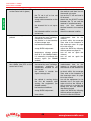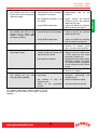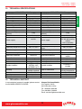
1
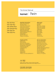
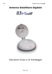
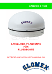
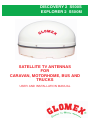
DISCOVERY 2 S500S
EXPLORER 2 S500M
SATELLITE TV ANTENNAS
FOR
CARAVAN, MOTORHOME, BUS AND
TRUCKS
USER AND INSTALLATION MANUAL
ENGLISH
DISCOVERY 2 S500S
EXPLORER 2 S500M
38
www.glomexmobile.com
DISCOVERY 2 S500S
EXPLORER 2 S500M
1. FOREWORD . . . . . . . . . . . . . . . . . . . . . . . . . . . . . . . . . . . . . . . . . . . . . . . . . . . . . . . . . . . 41
1.1 DELIVERY LETTER . . . . . . . . . . . . . . . . . . . . . . . . . . . . . . . . . . . . . . . . . . . . . . . . . . . . 41
1.2 ANTENNA IDENTIFICATION. . . . . . . . . . . . . . . . . . . . . . . . . . . . . . . . . . . . . . . . . . . . . 41
1.3 WARRANTY . . . . . . . . . . . . . . . . . . . . . . . . . . . . . . . . . . . . . . . . . . . . . . . . . . . . . . . . . . 41
1.4 GENERAL SAFETY INSTRUCTIONS . . . . . . . . . . . . . . . . . . . . . . . . . . . . . . . . . . . . . . 42
1.5 ENVIRONMENT . . . . . . . . . . . . . . . . . . . . . . . . . . . . . . . . . . . . . . . . . . . . . . . . . . . . . . . 42
2. PRODUCT DESCRIPTION . . . . . . . . . . . . . . . . . . . . . . . . . . . . . . . . . . . . . . . . . . . . . . . . 43
2.1 DISCOVERY 2 S500S . . . . . . . . . . . . . . . . . . . . . . . . . . . . . . . . . . . . . . . . . . . . . . . . . . 43
2.2 EXPLORER 2 S500M. . . . . . . . . . . . . . . . . . . . . . . . . . . . . . . . . . . . . . . . . . . . . . . . . . . 43
3. CONTENTS . . . . . . . . . . . . . . . . . . . . . . . . . . . . . . . . . . . . . . . . . . . . . . . . . . . . . . . . . . . . 44
3.1 OPTIONAL ACCESSORIES (NOT INCLUDED) TO USE GLOMEX ANTENNAS. . . . . 45
4.
NECESSARY TOOLS FOR ASSEMBLY (NOT PROVIDED) . . . . . . . . . . . . . . . . . . . . . . 45
5.
INSTALLATION . . . . . . . . . . . . . . . . . . . . . . . . . . . . . . . . . . . . . . . . . . . . . . . . . . . . . . . . . 46
6. ASSEMBLY . . . . . . . . . . . . . . . . . . . . . . . . . . . . . . . . . . . . . . . . . . . . . . . . . . . . . . . . . . . . 48
6.1 CUTTING TEMPLATE FOR BUILT-IN INSTALLATION OF THE CONTROL UNIT . . . 54
6.2 SKEW CALIBRATION (MANUAL) . . . . . . . . . . . . . . . . . . . . . . . . . . . . . . . . . . . . . . . . . 55
6.3 SKEW ADJUSTMENT GRID FOR EUROPE . . . . . . . . . . . . . . . . . . . . . . . . . . . . . . . . . 56
7. USE . . . . . . . . . . . . . . . . . . . . . . . . . . . . . . . . . . . . . . . . . . . . . . . . . . . . . . . . . . . . . . . . . . 58
7.1 HOW TO USE THE SLEEP MODE (S500M) . . . . . . . . . . . . . . . . . . . . . . . . . . . . . . . . . 60
8. TIPS FOR CORRECT USAGE . . . . . . . . . . . . . . . . . . . . . . . . . . . . . . . . . . . . . . . . . . . . . 61
8.1 FOOTPRINTS: SATELLITE TRANSMISSION AREAS . . . . . . . . . . . . . . . . . . . . . . . . . 62
9. MAINTENANCE. . . . . . . . . . . . . . . . . . . . . . . . . . . . . . . . . . . . . . . . . . . . . . . . . . . . . . . . . 63
9.1 PREVENTIVE MAINTENANCE . . . . . . . . . . . . . . . . . . . . . . . . . . . . . . . . . . . . . . . . . . . 63
9.2 SPARE PARTS . . . . . . . . . . . . . . . . . . . . . . . . . . . . . . . . . . . . . . . . . . . . . . . . . . . . . . . 63
9.3 SOFTWARE UPDATE BY SD CARD. . . . . . . . . . . . . . . . . . . . . . . . . . . . . . . . . . . . . . . 64
9.4 REPLACING THE POWER SUPPLY PROTECTION FUSE . . . . . . . . . . . . . . . . . . . . . 66
10. TROUBLESHOOTING. . . . . . . . . . . . . . . . . . . . . . . . . . . . . . . . . . . . . . . . . . . . . . . . . . . . 67
11. RESHIPPING. . . . . . . . . . . . . . . . . . . . . . . . . . . . . . . . . . . . . . . . . . . . . . . . . . . . . . . . . . . 70
12. TECHNICAL SPECIFICATIONS . . . . . . . . . . . . . . . . . . . . . . . . . . . . . . . . . . . . . . . . . . . . 71
13. TECHNICAL SUPPORT . . . . . . . . . . . . . . . . . . . . . . . . . . . . . . . . . . . . . . . . . . . . . . . . . . 71
www.glomexmobile.com
39
ENGLISH
INDEX
ENGLISH
DISCOVERY 2 S500S
EXPLORER 2 S500M
40
www.glomexmobile.com
DISCOVERY 2 S500S
EXPLORER 2 S500M
FOREWORD
1.1 DELIVERY LETTER
Welcome: with the installation of this antenna, the
world of satellite television comes on board your
vehicle.
This manual has been drafted in order to help you
with the correct installation and operation of the
antenna.
1.2 ANTENNA IDENTIFICATION
When calling GLOMEX or an authorized Service
Centre, always provide the serial number and the
model of the antenna, shown on the second page
of the manual, on the packaging, on the backside
of the control unit and on the backside of the
parabolic dish.
1.3 WARRANTY
GLOMEX guarantees the Discovery 2 S500S and
Explorer 2 S500M satellite antenna series against
conformity defects for a period of 24 (twenty-four)
months from the date of purchase.
Warranty is intended as the repair or replacement
of the equipment showing conformity defects when
entering the sales contract, with no charge for the
materials.
In case of conformity defects, the customer is
entitled to the replacement of the goods with no
charge.
The warranty is only valid if the product comes
with a valid proof of purchase, (receipt or
invoice).
The non-conforming product must be sent back to
a Service Centre or authorized retailer, who, if
necessary, will forward it to:
GLOMEX S.r.l.
Via Faentina 165/G
48124, Ravenna (Italy)
along with
purchase.
all
the
accessories
supplied
at
The serial number must neither be erased nor
made illegible, otherwise the warranty will be
invalidated.
S
The warranty does not apply in case of damage
due to carelessness, use or installation not
compliant with the instructions given, tampering,
product or serial number modification, damage due
to accidental causes or to the buyer’s negligence.
Moreover, warranty does not apply in case of
damage consequent to connections of the
equipment to different voltages than those
indicated or to sudden voltage variations of the
network the equipment is connected to, as well as
in case of damage caused by leakage, fire,
inductive/electrostatic discharges or discharges
due to lightning, use of cables different to those
provided, overvoltages or other phenomena not
related to the equipment.
The parts subject to wear consequent to use such
as connection cables, driving belts, connectors,
external parts and plastic supports are covered by
a one-year period warranty.
The warranty does not include: periodical checks,
software updates, product settings, maintenance.
After the expiration of the warranty period, the
technical support activities will be carried out
charging the customer for the replaced parts, the
labour costs and freight charges, according to
current rates.
The equipment will be replaced or repaired
under warranty only and exclusively on Glomex
quality department’s approval.
Should any dispute rise, the place of jurisdiction will
exclusively be Ravenna (Italy).
The warranty is provided by:
GLOMEX S.r.l.
Via Faentina 165/G
48124 Ravenna (Italy)
www.glomexmobile.com
WARNING
Please keep your Installation and User Manual in a
safe place! Losing the serial number makes the
warranty null and void!
41
ENGLISH
1.
DISCOVERY 2 S500S
EXPLORER 2 S500M
ENGLISH
1.4 GENERAL SAFETY INSTRUCTIONS
Carefully read the instructions given and follow the
precautions indicated to prevent potential hazards
and to safeguard your health and safety, before
carrying out any installation and maintenance
operation.
This manual contains the following indications:
WARNING
S
This symbol warns against potential damage to the
equipment which could involve the operator’s
safety.
DANGER
S
With specific warnings against potential dangers
for the safety of the operator or other directly
involved persons.
Failure to comply with the instructions preceded by
the above-mentioned keywords (WARNING and
DANGER) can cause serious accidents or even
the death of the persons involved.
Moreover, in this Manual, some instructions are
given with text in italics, preceded by the words
NOTE.
The information and specifications given in this
manual are based upon the information available at
the moment it is written.
In case of doubts, do not hesitate to contact
GLOMEX S.r.l.
1.5 ENVIRONMENT
Do not throw the appliance away with the normal
household waste at the end of its life, but hand it in
at an official point for recycling. By doing this, you
will help preserve the environment.
Fig. 1
42
www.glomexmobile.com
DISCOVERY 2 S500S
EXPLORER 2 S500M
2.
PRODUCT DESCRIPTION
2.1 DISCOVERY 2 S500S
ENGLISH
Discovery 2 S500S is a satellite TV antenna for
mobile vehicles, compatible with DVB (Digital
Video Broadcasting) satellite services.
It has a small size: a diameter of only 66 cm and a
height of 39 cm, with a weight of only 8 kg. It
operates with parked vehicle and with a very low
current consumption (0.6 A/h with 12 V).
It can be updated by SD card, to be inserted into
the relevant slot on the control unit side, in order to
have a constantly updated SAT TV antenna over
time.
The antenna covers the whole of Europe (see
coverage areas on page 62) and the available preloaded satellites are Astra2, Astra1, Hotbird.
2.2 EXPLORER 2 S500M
Explorer 2 S500M is a parabolic satellite TV
antenna for mobile vehicles with totally automatic
pointing, compatible with DVB (Digital Video
Broadcasting) satellite services. It has a small size:
a diameter of only 66 cm and a height of 39 cm,
with a weight of only 8 kg. It has a maximum
consumption (with moving vehicle) of approx. 1.2
A/h with 12 V and 1 A/h with parked vehicle.
It operates both with parked and with moving
vehicle.
Provided
with
next-generation
electronic
gyroscopes, it can compensate any kind of vehicle
movement during travel, thus allowing you to watch
your favourite TV programme during journeys and
with parked vehicle.
It can be updated by SD card, to be inserted into
the relevant slot on the control unit side, in order to
have a constantly updated SAT TV antenna over
time.
The antenna covers the whole of Europe (see
coverage areas on page 62) and the available preloaded satellites are Astra1 and Hotbird.
www.glomexmobile.com
43
DISCOVERY 2 S500S
EXPLORER 2 S500M
ENGLISH
3.
CONTENTS
The satellite antenna is sent packed in a cardboard
box and sealed with the GLOMEX “SAFETY SEAL”
hoop, which has the function of CONTENT
WARRANTY seal.
Upon receipt, check that:
- the packaging is whole and the warranty hoop is
present;
- the supply matches the order specifications;
- the antenna and its accessories are not
damaged.
Fig. 1
Decoder (not provided)
DISCOVERY 2 S500S
Component
GLOMEX code
Antenna unit (1)
3.010.0027
Control unit with wall-mounting
4.120.0102
bracket (2)
Coaxial cable, 5 m long, for
antenna
control
unit
V9140/5
connection, with integrated
protection (antenna side) (3)
Coaxial cable, 1.5 m long, for
control unit - sat decoder (4)
V9143
connection
Installation and user manual
Warranty certificate
Frame for built-in installation
Roof fairlead (enables cable
and connector passage)
In case of damage or missing parts, immediately
inform the Retailer, if possible with appropriate
photos.
The table below lists the components contained in
the package, indicating the quantities and the
GLOMEX code (if provided).
4.150.0055
4.150.0044
4.010.0432
T140
44
EXPLORER 2 S500M
Component
GLOMEX code
Antenna unit (1)
3.010.0028
Control unit with wall-mounting
4.120.0091A
bracket (2)
Coaxial cable, 5 m long, for
antenna
control
unit
V9140/5
connection, with integrated
protection (antenna side) (3)
Coaxial cable, 1.5 m long, for
control unit - sat decoder (4)
V9143
connection
Voltage stabilizer (5)
V9119
Installation and user manual
4.150.0055
Warranty certificate
4.150.0044
Frame for built-in installation
4.010.0432
Roof fairlead (enables cable
T140
and connector passage)
www.glomexmobile.com
DISCOVERY 2 S500S
EXPLORER 2 S500M
3.1 OPTIONAL ACCESSORIES (NOT
INCLUDED) TO USE GLOMEX
ANTENNAS
ENGLISH
To be able to use your new GLOMEX satellite
antenna for mobile vehicles, you will have to
procure or buy also:
- a TV set;
- a satellite receiver for channel selection.
The table below lists all the GLOMEX optional
components, with relevant code.
Optional accessory
Satellite receiver TIVÙSAT I-CAN 1110 SV
230 VAC - 12 VDC
SD card with new satellite
SD card with software update
Coaxial cable, 10 m long, for antenna - control unit
connection, with integrated moisture protection
4.
GLOMEX code
V9193
4.120.0077
4.120.0078
V9140/10M
NECESSARY TOOLS FOR
ASSEMBLY (NOT PROVIDED)
- Electric drill (1).
- Drill tips: 3.5 mm (for fastening the control unit to
solid wood or metal), 6 mm (for expansion plugs
in lightweight or hollow furniture or chipboard,
for fastening the control unit), 8 mm (for
fastening the radome) (2).
- ø 25 mm hole cutter (for cutting the hole for
fairlead assembly) (3).
- Phillips screwdriver (with adequate dimensions
for control unit opening) (4).
- 11 mm wrench (for the installation of the coaxial
cable connectors) (5).
- 2 mm Allen wrench (for M4 dowels) (6).
- Reciprocating saw (to drill a hole in case of wall
built-in installation of the control unit; use the
template provided on page 54) (7).
- Sealant like SIKAFLEX®252 (8).
WARNING
S
Plan the whole installation before proceeding!
Please consider the lay-out of the various
components, the distance between them, the
length of the various cables and the accessibility to
the equipment once it is installed.
Fig. 2
www.glomexmobile.com
45
DISCOVERY 2 S500S
EXPLORER 2 S500M
ENGLISH
5.
INSTALLATION
Since the GLOMEX satellite TV antenna requires a
clear view of the southern sky to receive satellite
signals, the ideal antenna site has an unobstructed
view of the satellite/horizon all around.
Keep the antenna clear of any obstructions
installed on the roof of the mobile vehicle (e.g., air
conditioners).
Obstacle height (A)
20 cm
25 cm
30 cm
35 cm
40 cm
Use the table below as a reference and install the
antenna at a correct distance from the obstructions
installed on the roof.
Minimum distance from the antenna (B)
75 cm
94 cm
112 cm
131 cm
150 cm
Obstructed signal!
Fig. 3
Typical antenna lifting
NORTHERN EUROPE (~ 15°)
CENTRAL EUROPE (~ 35°)
SOUTHERN EUROPE (~ 50°)
Fig. 4
46
www.glomexmobile.com
DISCOVERY 2 S500S
EXPLORER 2 S500M
ENGLISH
The antenna requires a lifting angle between 15°
and 50° to receive satellite signals.
Please also consider the position of the antenna
with respect to the position of all various
attachments or wiring harnesses necessary inside
the vehicle.
Make sure the antenna is installed on a flat
surface. When correctly installed on a flat surface,
the mounting plates should be positioned less than
1 mm from the surface.
WARNING
S
A higher distance than the one indicated will bend
Maximum gradient of the
mounting surface
the mounting plates and will seriously damage the
antenna!
Fig. 5
www.glomexmobile.com
47
DISCOVERY 2 S500S
EXPLORER 2 S500M
6.
ASSEMBLY
S
DANGER
ENGLISH
While installing the antenna, wear the appropriate
safety equipment for the job to be carried out.
Operations to be carried out outside the vehicle.
1. First of all, make sure you have chosen a
correct position to install the antenna (see
section 5: “Installation”).
2. Remove the antenna from the packaging box.
3. Carefully clean the 4 mounting plates (P) on the
antenna and the vehicle roof with alcohol and
let evaporate before applying the sealant (Fig.
6).
4. Apply some sealant like SIKAFLEX®252 on the
plates (Fig. 7).
5. Place the antenna in the appropriate position
on the vehicle middle line, respecting the
installation direction indicated in Fig. 8 and
apply a good pressure on the radome sides to
make the plates correctly adhere to the
mounting surface.
Wait for the sealant to solidify (time varies
according to outer temperature).
6. OPTIONAL OPERATION: remove the plates by
unscrewing the 2 nuts securing them to the
lower radome. Drill the lower radome with an
8 mm bit near the punching, put back the plates
and drill near the previously made holes, again
using an 8 mm (Fig. 9) bit.
Fig. 7
Fr
on
tv
eh
icl
e
pa
r
t
Mi
dd
le
lin
e
Output
connector
Fig. 8
P
P
P
P
Fig. 6
Fig. 9
48
www.glomexmobile.com
DISCOVERY 2 S500S
EXPLORER 2 S500M
S
ENGLISH
7. Select the zone (on the vehicle roof) where to
install the fairlead.
Before drilling the hole, make sure not to
damage possible pipes or cables.
Drill a hole by means of an electric drill and a
hole cutter with a diameter of 25 mm on the
vehicle roof for the passage of the 5 m coaxial
cable; use a fairlead code T140.
Apply some sealant like SIKAFLEX®252
around the hole (Fig. 10).
In case 2 cables are installed, by means of a
knife or a blade, remove a plastic tongue from
the fairlead, as indicated in Fig. 11.
Then apply the sealant as previously described.
Fig. 10
WARNING
Fastening with sealant is necessary and sufficient
for the correct use of the equipment.
Fastening with the screws (not included) of the
radome on the roof is optional.
Fastening with screws only does not guarantee
a perfect coupling of the radome to the roof.
GLOMEX declines any liability for an incorrect
coupling of the radome to the vehicle roof.
Fig. 11
www.glomexmobile.com
49
ENGLISH
DISCOVERY 2 S500S
EXPLORER 2 S500M
8. Mount the coaxial cable onto the antenna:
- make sure that the cable core is correctly
inserted in the central hole of the female
connector on the antenna (otherwise, there
would be a short circuit and the fuse installed
on the power supply line inside the control
unit would trip, see page 66 for fuse
replacement);
- manually screw in the ring nut of connector F;
- once the ring nut has been manually screwed
in, tighten by ¼ turn by means of a 11 mm
wrench;
- insert the protection;
- make the coaxial cable pass through the
previously bored 12 mm hole on the vehicle roof.
9. Insulate with appropriate sealants the holes
drilled in order to prevent water ingress.
S
WARNING
For a correct assembly, respect the installation
direction indicated in Fig. 8.
A different installation from the recommended one
could cause an incorrect operation of the antenna
due to the risk of water penetration into the
radome.
Operations to be carried out inside the vehicle.
1. Determine the correct position for the control
unit:
- it must be positioned near the satellite
receiver, as the provided coaxial cable is 1.5
m long;
- it must be reached by the power supply
cables coming directly from the battery;
- it must be reached by the coaxial cable
coming from the antenna (5 m long);
- it must be located in a dry and ventilated area.
2. Open the control unit by loosening the screws
with an appropriate screwdriver.
Central hole of
female connector
Fig. 12
Central cable
conductor
Fig. 14
WARNING
S
Should it be necessary to shorten the cable, please
refer to the instructions given in Fig. 15.
Fig. 13
NOTE: For the connection of the antenna
coaxial cable, it is not necessary to remove the
dome!
50
www.glomexmobile.com
DISCOVERY 2 S500S
EXPLORER 2 S500M
WARNING
S
The antenna is designed to operate with a single
ENGLISH
decoder; therefore, do not install signal splitters
upstream or downstream the control unit.
Power supply
cable
Red
Black
From the
To the receiver
Fig. 16
GL00095
Fig. 15
3. Connect the coaxial cable of the antenna
(previously installed) to the ANTENNA IN input on
the control unit and the 1.5 m coaxial cable to the
RECEIVER OUT output on the control unit.
Make sure that the cable conductors are correctly
inserted in the central holes of the relevant female
connectors on the control unit (otherwise, there
would be a short circuit and the fuse installed on
the power supply line inside the control unit would
trip, see page 66 for fuse replacement).
Manually screw in the ring nuts of connectors F.
Once the ring nuts have been manually screwed
in, tighten by ¼ turn by means of a 11 mm
wrench.
S
4a. Only for Discovery 2 S500S (Fig. 16)
Connect the power supply cable of the control
unit directly to the battery: connect the positive
terminal of the vehicle battery to the red cable
and the negative terminal to the black cable.
The power supply line coming from the battery
must have cables with a minimum cross
section of 2.5 mm2 with a length up to 4 m, of 4
mm2 for longer cables.
NOTE: With 5 m cable, MINIMUM power supply
11.5 V; with 10 m cable, MINIMUM power supply
12.5 V.
WARNING
The inversion of the two cables jeopardizes the
operation of the equipment. Make sure you have
correctly installed the coaxial cables. In case of
inversion, GLOMEX will not be directly liable for the
damage suffered by the receiver.
www.glomexmobile.com
51
WARNING
S
Do not use power supply from secondary circuits.
ANTENNA IN
ENGLISH
RECEIVER OUT
DISCOVERY 2 S500S
EXPLORER 2 S500M
This could
equipment.
jeopardize the operation of the
NOTE: The polarity inversion on the power supply
blows the fuse to prevent any damage to the
antenna (see page 66 for fuse replacement).
To the receiver
WARNING
S
Pay attention not to bend the coaxial cables at a
From the
antenna
right angle; the bending angle must always be
higher than 120°.
9
11
V9
Red
NO
Black
Fig. 17
4b. Only for Explorer 2 S500M (Fig. 17)
Connect the power supply cable of the control
unit to the connector of the power supply unit
V9119. Connect the power supply cable of unit
V9119 directly to the battery: connect the
positive terminal of the vehicle battery to the
red cable and the negative terminal to the
black cable. The power supply line coming
from the battery must have cables with a
minimum cross section of 2.5 mm2 with a
length up to 4 m, of 4 mm2 for longer cables.
NOTE: The connection of power supply unit V9119
is necessary for a correct operation of the
appliance. Its presence guarantees a stabilization
of the voltage coming from the vehicle battery.
WARNING
S
Make sure you have installed power supply unit
V9119 between vehicle battery and control unit for
the correct operation of the appliance!
52
NO
Fig. 18
NOTE: Do not cut the connectors of the coaxial
cables (the operation would not be guaranteed any
more) and always use the original GLOMEX cables
supplied, even with inappropriate dimensions (too
long). In case a longer cable is needed, ask the
authorized retailer for a 10 m coaxial cable,
provided on demand. Do not use different cables,
as it would jeopardize the operation of the
equipment.
5. Close the control unit by tightening the screws
in the rear cover.
www.glomexmobile.com
DISCOVERY 2 S500S
EXPLORER 2 S500M
ENGLISH
6. Fasten the control unit to the wall by using the
provided accessory (bracket) and screws.
Fig. 19
7. As an alternative, the control unit can be built-in
using off-the-shelf plates (3-module) or the
GLOMEX accessory (code 4.010.0432, see
Fig. 20) by boring a hole with a reciprocating
saw and using the drill with 2.5 mm bit (use the
cutting template on the following page for the
correct dimensions).
8. Connect the 1.5 m coaxial cable to the LNB IN
socket of the satellite receiver (not supplied).
www.glomexmobile.com
53
DISCOVERY 2 S500S
EXPLORER 2 S500M
ENGLISH
6.1 CUTTING TEMPLATE FOR BUILT-IN INSTALLATION OF THE CONTROL UNIT
4.010.0432
Fig. 20
54
www.glomexmobile.com
DISCOVERY 2 S500S
EXPLORER 2 S500M
Satellites can transmit in linear (Europe) or circular
(USA) polarisation. GLOMEX antennas are
designed to operate with a linear or circular
polarisation according to the installed LNB,
depending on the satellite whose transmission you
want to receive and on where you are positioned.
Circular polarisation does not require any
calibration for the optimization of the received
signal.
On the contrary, LNB operating with linear
polarisation need calibrating upon installation, in
order to optimize the alignment of the LNB with the
satellite whose transmission you want to receive.
When you are at the same longitude of the satellite,
its horizontal and vertical signals are aligned with
the horizon. When the satellite is east or west of
your position, the signal of the satellite will appear
as clockwise or counterclockwise shifted. Both the
horizontal and the vertical signal will be shifted by
the same angle, and therefore they will always be
perpendicular to each other.
The degree of rotation will depend on the distance
to the east or to the west between the position of
the antenna and the position of the satellite, and on
your distance from the equator.
Once you move to an area with a longitude more
than +/- 10° (corresponding to about 1000 km) from
the previous position, the LNB must be manually
adjusted in order to obtain the best possible signal.
Antennas are delivered with the LNB optimized for
an area with longitude 12° East while receiving
satellite 13° East.
For the adjustment of the LNB, proceed as follows:
- loosen the 8 screws on the radome and remove
it from the base;
- loosen the 3 M4 dowels (1) fastening the LNB
(2) to the disk by using a 2 mm Allen wrench
and manually move the dish, using the
parameter of signal quality of the digital
receiver in use as a reference for correct
calibration (please refer to the receiver’s
manual). Calibration does not need to be
changed if the vehicle remains in the same area
and receives transmission from the same
satellite.
Once the desired adjustment has been carried out,
tighten the 3 M4 dowels, position the radome onto
its base again and tighten the 8 fastening screws
again.
www.glomexmobile.com
ENGLISH
6.2 SKEW CALIBRATION (MANUAL)
Fig. 21
NOTE: Incorrect skew adjustment may cause a
number of problems, from no reception of some
channels up to the impossibility to find the selected
satellite.
55
DISCOVERY 2 S500S
EXPLORER 2 S500M
6.3 SKEW ADJUSTMENT GRID FOR
EUROPE
ENGLISH
To determine the values for adjusting the LNB, it is
possible to use the grid below and the relevant
table.
EGITTO
GIORDANIA
GL00096
Fig. 22
We recommend obtaining the values for the
adjustment of the SKEW by consulting the
website www.satbeams.com/footprints.
56
www.glomexmobile.com
Grid position
TURKSAT
42°E
ASTRA2
28.2°E
ASTRA3
23.5°E
ASTRA1
19.2°E
HOTBIRD
13.0°E
SIRIUS
4.8°E
THOR
1°W
HISPASAT
30°W
A (6°W 58°N)
-25°
-19°
-18°
-14°
-11°
-6°
-3°
14°
B (6°E 58°N)
-20°
-13°
-12°
-8°
-4°
0°
4°
20°
C (18°E 58°N)
-14°
-6°
-4°
0°
3°
8°
11°
24
D (30°E 58°N)
-7°
1°
3°
6°
10°
14°
17°
28°
E (42°E 58°N)
0°
7°
10°
13°
16°
20°
23°
30°
F (6°W 52°N)
-30°
-24°
-21°
-18°
-14°
-8°
-3°
17°
G (6°E 52°N)
-24°
-16°
-13°
-10°
-5°
0°
5°
24°
H (18°E 52°N)
-17°
-8°
-5°
0°
3°
9°
14°
34°
I (30°E 52°N)
-9°
1°
4°
8°
12°
18°
21°
36°
J (42°E 52°N)
0°
11°
12°
17°
20°
25°
28°
22°
K (6°W 45°N)
-36°
-29°
-27°
-23°
-18°
-10°
-5°
30°
L (6°E 45°N)
-30°
-20°
-20°
-12°
-7°
0°
6°
31°
M (18°E 45°N)
-22°
-9°
-8°
-1°
4°
12°
18°
36°
N (30°E 45°N)
-11°
2°
5°
10°
16°
22°
27°
40°
O (42°E 45°N)
0°
13°
17°
21°
25°
31°
34°
43°
P (6°W 38°N)
-43°
-35°
-36°
-28°
-22°
-13°
-6°
27°
Q (6°E 38°N)
-37°
-25°
-23°
-16°
-8°
1°
8°
36°
R (18°E 38°N)
-27°
-12°
-10°
-1°
6°
16°
22°
43°
S (30°E 38°N)
-15°
2°
8°
13°
20°
28°
33°
47°
T (42°E 38°N)
0°
17°
23°
26°
31°
37°
41°
50°
U (6°W 30°N)
-
-44°
-43°
-36°
-28°
-18°
-8°
35°
V (6°E 30°N)
-
-33°
-34°
-21°
-11°
1°
11°
45°
W (18°E 30°N)
-
-16°
-11°
-1°
8°
21°
29°
52°
X (30°E 30°N)
-
3°
10°
18°
25°
36°
41°
56°
Y (42°E 30°N)
-
22°
28°
34°
38°
46°
49°
58°
Turksat (42°E)
Sirius 4 (5°E)
Eurobird (9°E)
Astra 1 (19,2°E)
Astra 3 (23,5°E)
Hot-Bird (13°E)
Fig. 23
www.glomexmobile.com
GL00069
57
ENGLISH
DISCOVERY 2 S500S
EXPLORER 2 S500M
DISCOVERY 2 S500S
EXPLORER 2 S500M
7.
USE
ENGLISH
Flow chart
POWER ON
POWER ON KEY
CALIBRATION
SATELLITE SEARCH
RED LIGHT
SATELLITE FOUND
SATELLITE CHECK AND
IDENTIFICATION
ORANGE LIGHT
IS IT THE SELECTED
SATELLITE?
NO
YES
SATELLITE FOUND
GREEN LIGHT
Fig. 24
58
www.glomexmobile.com
DISCOVERY 2 S500S
EXPLORER 2 S500M
www.glomexmobile.com
WARNING
S
If the LED flashes alternately red and green,
this means that the antenna is not connected to
the control unit or that a failure has occurred.
See section “Troubleshooting” or contact the
Service Centre.
Fig. 25
A. Satellite selector
B. Power on key
C. LED
59
ENGLISH
1. In case of use with a stationary vehicle, park the
vehicle in an obstacle-free area.
2. Turn on the receiver and the TV set. For details
about the use of the receiver and the TV set,
please refer to the relevant user manuals
provided by the relevant manufacturers.
3. On the control unit, by means of the relevant
selector (A), select the desired satellite (ASTRA
1, ASTRA 2, HOTBIRD on S500S, ASTRA1 or
HOTBIRD on S500M).
4. Turn on the control unit (set (B) key to ON).
5. After a few seconds, the LED (C) turns red, and
this means that the antenna is searching for the
signal.
6. If the antenna has found a satellite signal, the
LED turns orange and starts checking that the
found satellite is the selected one. Verification
can take up to 30 seconds.
7. If, after a few seconds, the LED turns green, it
means that the found satellite is the correct
one. Otherwise, the LED turns red again, and
the satellite searching procedure is restarted.
8. With green LED, after a few seconds, the image
will appear on the TV set. Follow the
instructions appearing on the screen to set the
parameters for a correct operation of the
receiver.
9. Automatic stand-by function (applies to
S500M):
once the satellite has been verified (green LED
on the control unit), after about 2 minutes of the
vehicle remaining stationary, the antenna stops
in the position where the signal reception from
the satellite is at it's maximum.
A reduction of the received signal or a total shift
of the vehicle of 6° in 2 minutes “will wake the
antenna up” in order that it recovers the
maximum receivable signal level.
People getting into, getting out of or moving
inside the vehicle could make the antenna exit
the standby mode.
This function can be disabled by positioning the
satellite selector to the middle "Sleep" position
(see the following page).
This function is useful at night to prevent the
antenna from "waking up" and thus making
undesirable noise.
DISCOVERY 2 S500S
EXPLORER 2 S500M
7.1 HOW TO USE THE SLEEP MODE
(S500M)
ENGLISH
The first time you need to select the desired
satellite (ASTRA1 or HOTBIRD).
When you want to select the other satellite you
have to switch off the antenna, select the desired
satellite on the control unit, switch on the antenna
and it will search again for it.
Then you can select the SLEEP mode again to
stop the antenna.
SLEEP
ASTRA
1
TBIRD
HO
Fig. 26
The antenna will search for the satellite and, after
recognizing it correctly (GREEN light), you can
select the SLEEP position.
TBIRD
HO
ASTRA
1
SLEEP
Fig. 27
In sleep mode, the antenna will stop and it will not
enter the tracking mode. It means that, if the
vehicle moves, the antenna will lose the signal.
Once the antenna is switched off, if the vehicle
does not move, you can switch the antenna on
again directly in sleep mode.
When you move to a different location you have to
switch off the antenna, select the desired satellite
on the control unit, switch on the antenna and it will
search again for it.
Then you can select the SLEEP mode again to
stop the antenna.
60
www.glomexmobile.com
DISCOVERY 2 S500S
EXPLORER 2 S500M
TIPS FOR CORRECT USAGE
GLOMEX recommends observing the following
indications for the correct use of the equipment.
- The receiver must be activated before receiving
the satellite programmes.
- Keep the radome always mounted on the
antenna. Its task is to protect all inner (fixed and
moving) parts from wind, rain and dust.
- Do not lean against and/or sit on the antenna!
- Pay attention not to spill liquids of any kind into
the antenna.
- The antenna should be cleaned periodically.
Dust or dirt accumulated on the radome could
affect the satellite signal reception. Clean the
radome with a damp cloth. DO NOT USE
BRUSHES,
ABRASIVE
PRODUCTS,
DETERGENTS
OR
ALCOHOL-BASED
LIQUIDS.
- Do not paint the surface of the radome! This
would negatively affect signal receipt.
- The antenna requires a clear view of the sky to
receive satellite signals. Possible very common
signal obstructions include trees, buildings,
overpasses, mountains, bridges and galleries.
GLOMEX antennas also do not operate inside
garages.
NOTE: (S500M) Upon start-up, the antenna
calibrates the sensors.
Should the signal be unstable during travel, we
recommend turning off and on again the
antenna while travelling.
In this way, the antenna calibrates the sensors
again.
NOTE: (S500M) Environmental temperature
changes may influence the response of the
sensors inside the antenna (gyroscopes), making
signal pointing less precise.
Should the signal be unstable during travel, we
recommend turning off and on again the
antenna while travelling.
obstruction
of signal
Fig. 28
- Heavy rain or snow could temporarily interrupt
signal reception from the satellite.
- The vehicle must be within the coverage area of
the selected satellite to receive the desired
signal. Please refer to the satellite coverage
footprints on the following page.
- At the end of its life, do not dispose the antenna or
its components into the environment, but take
advantage of specialized waste disposal agencies.
WARNING
S
Bad weather conditions affect the quality of the
signal and reduce image quality!
Fig. 29
www.glomexmobile.com
61
ENGLISH
8.
DISCOVERY 2 S500S
EXPLORER 2 S500M
ENGLISH
8.1 FOOTPRINTS: SATELLITE
TRANSMISSION AREAS
Satellite television is one of the few means which
allows the reception of information in any part of
the world within the coverage area of the satellite
you wish to receive.
The signal transmitted by the satellite generally has
a wide coverage area, as shown in the purely
indicative footprints below, and thus guarantees
vision of the same TV programmes in various
areas.
However, it is important to remember that ground
obstacles are the main causes of satellite antenna
malfunction.
Ground obstacles include all bodies which could be
located between satellite and antenna, such as
trees, cranes, buildings, overpasses, bridges,
galleries, etc.
The signal transmitted by the satellite is also
affected by weather conditions (storm clouds or ice
clouds).
The footprints show the satellite coverage areas on
the Earth for satellite antennas Discovery and
Explorer under favourable weather conditions.
S
WARNING
In case of bad weather, signals will be weaker;
therefore, the image quality could be reduced, up
to completely fading away. It is also very important
to make sure, upon purchase, that the dimensions
of the satellite antenna are the most appropriate
ones to receive the signal in the areas where you
spend your holiday. Footprints are indicative and
referred to the satellite with the strongest E.I.R.P.
(Equivalent Isotropic Radiated Power).
ASTRA 1 - 19° E
ASTRA 2 - 28° E Broad Beam M
HOTBIRD - 13° E
ASTRA 2 UK - 28° E Spot Beam L
GL00150
Fig. 30
62
www.glomexmobile.com
DISCOVERY 2 S500S
EXPLORER 2 S500M
MAINTENANCE
9.1 PREVENTIVE MAINTENANCE
GLOMEX antennas DISCOVERY 2 S500S and
EXPLORER 2 S500M require minimum preventive
maintenance.
Observing the following instructions is sufficient to
maintain a high equipment performance.
Monthly checks
- Wash the radome surface with a damp cloth; do
not direct pressurized water jets onto the
radome.
S
WARNING
Do not use brushes, abrasive products, detergents
or alcohol-based liquids.
Yearly checks
- Check the outer conditions of the radome. Clean
from dust and dirt if necessary.
Checks before any long travel
- Check that the mounting plates of the radome
are correctly glued
- Check for the correct installation of the 5 m
coaxial cable protection on the antenna.
GLOMEX DISCOVERY 2 S500S and EXPLORER
2 S500M antennas have been designed for a long
life and for minimum maintenance.
Should you have problems with the operation or in
case you need technical support, first of all contact
the authorized Retailer. Keep at hand the serial
number of your antenna (on page 2 in this manual)
and a list of the faults. Should no Retailer be
available, contact the GLOMEX Service Centre
(see section “Technical Support”).
S
WARNING
S
WARNING
You will be asked the serial number of your
antenna during any service or troubleshooting
phone call. The serial number is found on page 2 of
the user manual of your antenna, on the
packaging, on the backside of the control unit and
on the parabolic dish.
Please keep your Installation and User Manual in a
safe place, as it contains the serial number of your
antenna!
DANGER
S
Before carrying out any maintenance or cleaning
operation, or after each use, ALWAYS turn off the
antenna by means of the switch located on the
control unit.
9.2 SPARE PARTS
The following table lists the codes of the
components which can be supplied as spare parts
directly by the Retailer.
Spare parts
Lower radome S500S
Upper radome S500S
Lower radome S500M
Upper radome S500M
Fastening foot for antenna base
Fuse for control unit T3A15 5x20
www.glomexmobile.com
GLOMEX code
S500S-LR
S500S-UR
S500M-LR
S500M-UR
4.010.0250
4.120.0076
63
ENGLISH
9.
DISCOVERY 2 S500S
EXPLORER 2 S500M
ENGLISH
9.3 SOFTWARE UPDATE BY SD CARD
The SD card must be inserted into the relevant slot
on the control unit side.
The SD CARD used for updating must be
formatted in FAT32, cluster size 4096 bytes (4k)
and with empty volume label. It is therefore
necessary to copy file DATA.NID (DISCOVERY 2
S500S) or the file S500M.DAT (S500M
EXPLORER 2) provided onto the SD card,
proceeding as follows:
1. Turn off the decoder, the TV set and make sure
that the switch on the control unit is set to OFF.
2. Remove the control unit from the wall-mounting
bracket (see Fig. 19), open the box by
loosening the screws (see Fig. 14).
3. OPTIONAL (in case of built-in installation):
remove the wall-mounting plate (see Fig. 20),
loosen the screws and remove the built-in
control unit.
4. Insert the SD card into the relevant slot on the
control unit side, as indicated in Fig. 31,
respecting the direction (side with manufacturer
label up) and making sure you have completely
inserted it.
5. Turn on the control unit (set B key, Fig. 25, to
ON).
6. If the control unit detects the presence of a SD
card with original GLOMEX software, the LED
turns orange and automatically starts the
software updating procedure.
7. If the LED stays red and the antenna moves,
this means that no original GLOMEX software
has been detected, or that the SD card has not
been inserted completely. Turn off the control
unit and repeat the procedure from step 5.
NOTE: if the control unit is not immediately turned
off, in a few seconds the LED will turn orange and
then green, according to the standard satellite
searching procedure; turn off anyway and repeat
the procedure from step 5.
64
8. If the update is correctly carried out, the LED
turns green. Otherwise, the LED turns red and it
is necessary to turn off the control unit and to
repeat the procedure from step 5.
9. Turn off the control unit, remove the SD card
and reinstall the rear cover onto the control unit.
10. OPTIONAL (in case of built-in installation):
insert the control unit into the wall, reinstall the
fastening screws and the installation plate.
S
WARNING
In case of repeated failures in the software update
procedure, please contact the GLOMEX Service
Centre.
Fig. 31
NOTE: it is possible to download the necessary
software update file from the Glomex website
(www.glomexmobile.com) in section “Technical
Support - Download Area”.
www.glomexmobile.com
DISCOVERY 2 S500S
EXPLORER 2 S500M
Flowchart software update
ENGLISH
SD UPDATE
SD INTRODUCTION
ORANGE LED
TURN THE CONTROL
UNIT ON AGAIN
NO
CHECK THE SD CARD
YES
SOFTWARE UPDATE
TURN OFF THE
CONTROL UNIT
UPDATE
COMPLETED
NO
RED LED
YES
GREEN LED
Fig. 32
www.glomexmobile.com
65
DISCOVERY 2 S500S
EXPLORER 2 S500M
9.4 REPLACING THE POWER SUPPLY
PROTECTION FUSE
ENGLISH
In case the fuse on the power supply line has
blown, proceed as follows to replace it:
- Turn off the decoder, the TV set and make sure
that the switch on the control unit is set to OFF.
- Remove the control unit from the wall-mounting
bracket, open the box by loosening the screws.
- OPTIONAL: (in case of built-in installation):
remove the wall-mounting plate (see Fig. 20),
loosen the screws and remove the built-in
control unit.
- Disconnect the power supply cable from the
battery.
- Remove the blown fuse from its seat indicated in
Fig. 33 and replace it with a new one (type T
3.15A L 250 VAC 5x20, i.e. Time Delay Fuse,
with 5 mm diameter and 20 mm length, 3.15 A
rated current and 250 V rated voltage).
- Connect the power supply to the battery again.
- Reinstall the rear cover onto the control unit.
- OPTIONAL (in case of built-in installation):
insert the control unit into the wall, reinstall the
fastening screws and the installation plate.
S
Fig. 33
WARNING
In case the fuse blows again, a short circuit on the
coaxial cable or on the power supply cable could
be the cause.
Check that the cables are not short-circuited.
DANGER
S
Do not supply the antenna by connecting the 2
wires of the positive pole without using the fuse.
A fire could break out as a result of a short circuit.
66
www.glomexmobile.com
DISCOVERY 2 S500S
EXPLORER 2 S500M
When a malfunction of your satellite system
occurs, it is very important to make a rapid check to
understand the nature of the malfunction and, if
possible, to find a remedy.
To analyze a malfunction, it is appropriate to carry
out the following checks:
- the malfunction has been generated through
human error;
- the malfunction is due to a weather problem;
- the malfunction is due to a failure of the
equipment itself or it is caused by an anomaly of
another external appliance, which is connected
to the equipment;
- in which phase the malfunction occurs: upon
start-up, during normal operation, upon shutdown;
- the malfunction is repeated; if so, according to
what criteria;
- what the malfuction is. Determined from a
functional point of view;
- whether the malfunction produces signals (light
signals) and/or abnormal noises (such as
hissing, buzzing, etc.) and/or abnormal odours
(smell of burning) or not;
- the malfunction interferes with the operation of
other appliances;
- the malfunction is an apparent failure (i.e. it
disappears, for example, by turning off and then
on again the equipment).
The better you are able to answer the abovementioned questions, the deeper the malfunction
analysis will be.
The following table analyzes the most probable
causes which can lead to malfunctions of your
GLOMEX DISCOVERY 2 S500S or EXPLORER 2
S500M antenna. For any analyzed possible cause,
a corrective measure is proposed, to efficiently
solve, as much as possible, the fault.
Anomaly
Cause
Remedy
1. The antenna does not operate - the fuse is blown
- replace the blown fuse with a
(the LED on the control unit
new
one
(see
section
does not turn on)
“Maintenance”)
- wrong power supply cable - check the polarity on the
connection
power supply line
- short-circuited coaxial cable
- check the correct mounting of
the coaxial cables
- proper failure
- contact the Service Centre
2. The antenna does not operate - the coaxial cable has loosened - check the connection of the
(the LED on the control unit
or has disconnected from the
coaxial cables
flashes alternately red and
antenna
green)
- inner failure
- contact the Service Centre
3. No status message on the - the satellite receiver is not - check the receiver connection
decoder
installed correctly
- alternating current fluctuations - refer to the user manual of the
receiver for support
www.glomexmobile.com
67
ENGLISH
10. TROUBLESHOOTING
DISCOVERY 2 S500S
EXPLORER 2 S500M
ENGLISH
4. No image on the TV (the LED - the receiver is off
on the control unit is green)
- the TV set is off or has not
been tuned to AV
- wrong cable connection on the
receiver
- the channel list is not up-todate
- turn off the control unit, turn on
the receiver and then turn on
the control unit again
- turn on the TV set and tune to
AV channel
- check that the SCART socket
between the TV set and the
receiver is installed correctly
- carry out the automatic
channel search in the receiver
menu
- check the selected satellite
- the selected satellite is not the
correct one
5. Intermittent images for short - the satellite signals are - move the vehicle to allow an
periods
obstructed by trees, buildings,
unobstructed view for the
overpasses, mountains
antenna
- the vehicle is at the boundary - go back within the coverage
of the coverage area
area; refer to the footprints of
the coverage areas on page
- bad weather conditions
62 in this manual
- wrong SKEW adjustment
- adjust the SKEW by following
the instructions on page 55
- temperature change greater - turn off and on again the
than 10°C (for S500M models)
antenna
- it is necessary to calibrate the - turn off and on again the
sensors again (for S500M
antenna
models)
6. The equipment does not find - the satellite signals are - move the vehicle to allow an
the satellite (the LED on the
obstructed by trees, buildings,
unobstructed view for the
control unit is red)
overpasses, mountains or
antenna or correctly position
attachments installed on the
the antenna on the vehicle roof
vehicle roof
- the vehicle is outside the - go back within the coverage
signal coverage area
area; refer to the footprints of
the coverage areas on page
62 in this manual
- the vehicle is moving during - turn off the equipment for 10
the first 60 seconds after
seconds, turn it on again and
starting the equipment (for
make sure that the vehicle is
S500M models)
still or moves in a straight line
during the first 60 seconds
- bad weather conditions
after being started
- wrong SKEW adjustment
- adjust the SKEW by following
the instructions on page 55
- inner failure
- contact the Service Centre
68
www.glomexmobile.com
7. The equipment does not find - the satellite signals are - move the vehicle to allow an
the satellite (the LED on the
obstructed by trees, buildings,
unobstructed view for the
control unit flashes alternately
overpasses, mountains
antenna
red and orange)
- the equipment software is not - please contact the Service
up to date
Centre to ask for the software
update by SD card
- wrong SKEW adjustment
- adjust the SKEW by following
the instructions on page 55
8. The equipment does not find - parameters
in
satellite - please contact the Service
the satellite (the LED on the
communication have changed
Centre to ask for the software
control unit is orange and
update by SD card
remains orange also when
moving the vehicle)
- wrong SKEW adjustment
- adjust the SKEW by following
the instructions on page 55
9. Disturbed images
- failure of the receiver
- refer to the user manual of the
receiver for support, spare
parts and warranty conditions.
10. Confused, incomplete and - condensate or rain on the - remove
the
condensate
obstructed images
radome, which can disturb the
deposits from the radome with
signal with still vehicle
a fresh water jet (not under
pressure) or with a rag
- bad weather conditions
- periodically wash using a liquid
detergent suitable for dishes
(no alcohol-based detergent)
on the radome surface and let
dry up
11. The decoder blocks
- alternating current fluctuations - refer to the user manual of the
receiver for support
12. The equipment operates with - the
satellite
signal
is - move away from possible
still vehicle but not with
obstructed
obstacles
obstructing
the
moving vehicle (S500M)
satellite signal
- the antenna is only for - check the antenna model
stationary use
- failure in the gyroscope - contact the Service Centre
system
For further information, please address to the
GLOMEX Service Centre (see section “Technical
Support”).
www.glomexmobile.com
69
ENGLISH
DISCOVERY 2 S500S
EXPLORER 2 S500M
DISCOVERY 2 S500S
EXPLORER 2 S500M
ENGLISH
11. RESHIPPING
Should you need to return the antenna to
GLOMEX, place it in a box, possibly the original
one, making sure it is well packaged and that the
upper and lower side are well recognizable.
In order to prevent any damage to the antenna
during transport, it is necessary to send it inside the
original radome (upper and lower).
Together with the antenna, please also send the
control unit, so that a verification of the whole
system is possible.
NOTE: GLOMEX will not be liable for possible
damage occurred during transport due to
incorrect packaging.
WARNING
S
Do not ship the antenna to GLOMEX for repairs
without having received a corresponding
authorization to return the material (RMA), as
reported in the general warranty/support
conditions.
NOTE: to remove the antenna from the vehicle,
just remove the upper radome by unscrewing the 8
screws near the base, unscrew the 2 screws on
each fastening foot and lift the antenna from the
lower radome.
The feet remain glued to the vehicle for a
subsequent new installation. After its removal from
the vehicle, fasten the upper radome onto the lower
one again using the 8 screws previously removed.
70
www.glomexmobile.com
DISCOVERY 2 S500S
EXPLORER 2 S500M
DISCOVERY 2 S500S
Min E.I.R.P.
48 dBW
Antenna gain
35 db
Dish size
58 cm x 32 cm
Antenna type
OFFSET + H.P.F.
Antenna Polarisation
Linear V/H
LNB frequency range
10.7 to 12.75 GHz
Radome type
UV resistant
Radome diameter
66 cm
Radome Height
39 cm
Antenna weight (including
8 kg
radome)
Transmission
Gear
11,5 ÷ 13.8 VDC/
0.6 A/h
Power supply
Peak
Elevation range
Azimuth turn range
15° to 50°
Unlimited
Peak
Operating
temperature
range
Elevation range
Azimuth turn range
Operating conditions
Stationary
Operating conditions
Operating temperature range
Acquisition time
Loaded satellites
Working
Skew
Standby
SD card reader
2.5 A
EXPLORER 2 S500M
Min E.I.R.P.
48 dBW
Antenna gain
35 db
Dish size
58 cm x 32 cm
Antenna type
OFFSET + H.P.F.
Antenna Polarisation
Linear V/H
LNB frequency range
10.7 to 12.75 GHz
Radome type
UV resistant
Radome diameter
66 cm
Radome Height
39 cm
Antenna weight (including
8 kg
radome)
Transmission
Gear
11,5 ÷ 13.8 VDC/
1.2 A/h with moving
Power supply
vehicle
-20°C to +55°C
40 sec (approx.)
ASTRA1 19°E
ASTRA2 28°E
HOTBIRD 13°E
Only when the
vehicle is parked
Manual
Automatic
Yes
Acquisition time (stationary)
Tracking time (In-motion)
Tracking rate
Loaded satellites
Type of stabilization
Skew
Standby
SD card reader
1 A/h in stand-by
2.5 A
-20°C to +55°C
15° to 50°
Unlimited
Stationary and inmotion
< 40 sec
< 50 sec
> 50° / sec
2 satellites + 1
standby
Gyro on 2 axis +3°
axis by interpolation
Manual
Manual
Yes
13. TECHNICAL SUPPORT
In case technical support is needed, please contact
the GLOMEX SERVICE CENTRE:
www.glomexmobile.com
Glomex Divisione Mobile
Via Faentina 165/G
48124 Ravenna (Italy)
Tel. +39 0544 1936106
Fax +39 0544 1930164
Email: [email protected]
71
ENGLISH
12. TECHNICAL SPECIFICATIONS
DISCOVERY 2 S500S
EXPLORER 2 S500M
ENGLISH
NOTES:
72
www.glomexmobile.com