1
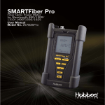
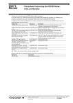
Optical Power Multi Meter
User Manual
V2.0
Contents
I.Summary ...........................................................................1
II.Functions ..........................................................................2
III.Technical Specifications ................................................2
IV.Layout ..............................................................................4
V.Operation..........................................................................5
VI. Maintenance................................................................10
VII. Faults & Solutions .....................................................12
1. Summary
Combining optical source and optical power meter in
one, Optical Power Multi Meter is a portable and intelligent
instrument for optical network test. There are inner
1310nm and 1550nm dual wavelength output optical
source. It can fulfill the functions of steady optical source
and optical power meter at the same time, and it realizes
the loop test and two-way automatic test. Its single-end
test solution greatly advances the test efficiency. The inner
microprocessor and linearity magnification technology
ensure the long time calibration and test accuracy.
Optical Power Multi meter can carry out not only the
absolute and relative power test, but also the optical loss
test for fiber, optical cable and optical passive devices
automatically, and it can save test results. It is suitable for
construction, maintenance of fiber communication and
CATV system; meanwhile, it is used for laboratory test and
R&D. It is an ideal portable tool for fiber project staff.
II. Functions
1. Multi wavelength exact test
2. Absolute power test for dBm or μW
3. Relative power test for dB
4. Single end for dual wavelength output, free switch from
1310 nm and 1550 nm
5. 200 groups of test data storage and management
6. Multi adapters(FC, SC, ST ,LC)
7. Handheld, large LCD display, easy to operate
8. under voltage indication
9. Auto power off in 10 minutes
10. Auto Backlight off in 60 seconds
11. USB communication
12. With real-time clock function, can real-time display the
current time, provide recording time for data storage
III . Technical Specifications
Ø
optical power meter module
1. Wavelength range:800~1600 nm
2. Detector type:InGaAs
3. Optical power test range:-45~+25dBm
4. Uncertainty:±5%
5. Resolution:Linearity display 0.1%, logarithm display
0.01dBm
6. Automatic frequency identification: 270Hz、1KHz、2KHz
optical source module
1. Emitter type:FP-LD/DFB-LD
2. Dual wavelength switch function: 1310±20nm,
1550±20nm
3. Spectral line width:≤5nm
4. Output optical power:≥-7 dBm
5. Short-time stability of output optical power:
≤±0.05dB/15min
6. Long-time stability of output optical power:≤±0.1dB/5h
Ø
Ø Others
1. Low voltage indication:There is indication when battery
voltage is lower than 3.4V
2. Time for auto power-off:10 min
3. Working duration for battery:
≥70h (the optical source and optical power meter work
synchronously)
≥140h (only optical power meter work)
4. Battery: 3.7V/2500mAh high-performance rechargeable
lithium battery
5. Operating temperature:0℃~40℃
Storage temperature:-10℃~+60℃
6. Weight: 0.2Kg
7. Dimension:160mm×76 mm×28 mm
IV.Layout
Browse Record
Save Record
Date and Time
Auto Power off
Wavelength
Optical
Auto
backlight
off
Power 1
Optical
Power 2
5
4
2
6
1
3
V. Operation
Introduction for optical power meter module
1. On/Off key:Pressing On/Off key can open and close the
tester. The tester will use the auto power off as default
status when you open the tester. Turn off auto power off
Ø
function: In power-on state, press
key and dBm/dB
key together, and lift up the two keys simultaneously, you
will see automatic power off mark disappear from the
screen. Turn on automatic power-off function: In power-on
state, press
key and dBm/dB key together, and lift up
the two keys simultaneously, you will see automatic poweroff mark displayed on the screen.
2. Unit key: The instrument defaults the absolute
measurement of optical power. The value displayed by
optical power1 means linear power value (nW); The value
displayed by optical power2 means logarithmic power
value (dBm). Press the dBm/dB key, system will switch to
relative power test state. In this case, the value displayed
by optical power1 means logarithmic power value (dBm)
and the value displayed by optical power2 means relative
power value (dB).
3. Wavelength key:You can choose one of four kinds of
wavelengths: 850nm, 1310nm, 1550nm and 1625nm
through this key. The chosen wavelength will be displayed
in the right top corner of the LCD screen. When the
instrument is power-on, it defaults the wavelength of
1310nm, and circulates in order of 1310nm, 1550nm,
1625nm and 850nm.
4. Save key:The storage function for current test data can
be realized by pressing this key. Storage mark will be
displayed on the LCD screen. When the storage mark
disappears from the screen, it means data storage is
completed. The system can store 200 pieces of records.
When the storage groups exceed 200 pieces, it will cover
the first piece automatically.
5. Browse key:Press this key, the browse mark will be
displayed on the LCD screen, this means the system is in
data recall state. The last saved data will be displayed on
the LCD screen. Press this key again and the browse mark
disappears, the system exits data browse state and returns
to normal state. In browse state, press the key“▲”can
realize page up browsing function for saved data; Press
the key“▼”can realize page down browsing function for
saved data.
6. Backlight key: When power-on, the system defaults
backlight-on, auto backlight-off mark is displayed on the
LCD screen. At the same time auto backlight-off function is
open. Pressing this key, backlight is off; pressing this key
again, backlight is on. In the state of auto backlight-off,
pressing “backlight” key and “wavelength” key together,
automatic backlight-off mark disappears from the LCD
screen, and the function of auto backlight-off is closed. In
the state of auto backlight-off is closed, press “backlight”
key and “wavelength” key together, auto backlight-off
mark displays on the LCD screen, and the function of
auto backlight-off is open.
7. Time check: Press “recall” key and “unit” key together,
and lift up the two keys simultaneously, the system enters
time check state. Press “store” key and select the time
position which will be adjusted, press the key“▲”and “▼”to
adjust the selected time position. Press “browse” key and
“wavelength” key together and lift up the two keys
simultaneously to adjust the time and exit time check state,
then enter normal state.
8. Frequency automatic identification: When optical signal
has modulation information, the system can identify optical
signal of 270Hz, 1KHz, 2KHz automatically.
Ø
Stable Optical Source Module
After the instrument is powered on, the default state of
optical source module is in the closed state. In the optical
power test state, press “Mode” key, the instrument enters
optical source output state. Optical power1 does not
display any data while optical power2 displays the
modulation mode of the output optical signal: CW,
270Hz,1KHz、2KHz.
Enter the optical source output state; no optical signal
is output at first. Wavelength of 1310nm and 1550nm can
be chosen by press “wavelength” key. After choose a
wavelength, modulation mode of the output optical signal:
CW 、 270Hz 、 1KHz 、 2KHz can be selected by
press“▲”or“▼”.
When optical signal is output, backlight mark will
shine all the time. Press “Mode” key again, the system will
return optical power test state. In this case two modules
can work at the same time.
Ø
Other functions
1. Under voltage indication function: When the voltage
of battery is under 3.4V, the sign
will be displayed on
the LCD screen, the battery should be charged at once.
2.Battery charge: During the operation period, if under
voltage sign appearances, please power off the instrument
and charge the battery by using relative charger. The
indication light of charger is red when it is in charge, and it
will be green when it is full of voltage.
3.Data communication function
By using WINDOWS hyper terminal software, baud
rate is 19200, data bits is 8 bits, stop bits is 1 bit, no parity
bit, no flow control, send commands according to the
following table, you can operate ST801 accordingly.
Character Sent Instructions Table:
Instruction
Instruction
name
word
Menu
M
Function
Pick
Remark
up
and
read
Sent
main
instructions:
M
instructions:
D
instructions:
H
ENTER
menu
Real-time
D
test
History
H
record
Time check
T nn/yy/rr
Real-time
Sent
power display
ENTER
Recall
Sent
history
record
ENTER
Set time
A space between date and
hh:mm:ss
time
For example:
09/01/05 11:15:00
Sent
instructions : T
09/01/05 11:15:00 ENTER
Wavelength
Ln
set
Test mode
Fn
Set wavelength
Sent
n 0-5
ENTER
Set test mode
Sent
instructions:
L
instructions:
F
ENTER
Hexadecimal Sent Instructions Table:
Instruction
Instruction
name
word
Menu
4D
Function
Pick
up
Remark
and
Sent instructions:4D 0D
read
main
menu
Real-time
44
test
History
Wavelength
Sent instructions:44 0D
power display
48
record
Time check
Real-time
Recall
history
Sent instructions:48 0D
record
54 20 xx xx
Set time
For example:
2F xx xx 2F
09/01/05 11:15:00
xx xx 20 xx
Sent instructions:
xx 3A xx xx
54 20 30 39 2F 30 31 2F 30 35
3A xx xx 0d
20 31 31 3A 31 35 3A 30 30 0d
4C
set
Set
wavelength
Sent instructions:4C 20 33 0D
n
0-5
Test mode
46
Set test mode
Sent instructions:46 20 30 0D
VI. Maintenance
1. The instrument should be avoided to shock, hit, fall off
and other mechanical damage. Meanwhile, it should be
avoided to touch acid, alkali and other harmful matters.
2.To keep the photoelectric sensor interface and laser
connector interface clean; do not use dirty or non standard
adaptor tie-in; do not insert the bad polished interface,
otherwise, the sensor interface and laser interface will be
damaged. Please clean the fiber jump line ceramic core
interface using absorbent cotton and alcohol before it is
operated. After the alcohol is dry then you can use the
instrument.
3.When you use different kinds of adapter to test, please
screw the FC type adapter of the photoelectricity sensor
and then insert the ceramic core of different adapter into
the photoelectricity sensor to test. Please keep the FC type
adapter, which is screwed carefully to avoid the dust. After
the test, the FC type adapter should be screwed again.
4. Please cover the dust proof cap of photoelectricity
sensor and laser connector when the instrument is not
operated for a long time, to keep it clean and avoid the test
error caused by circs, that the sensor and laser connector
uncovered in the air for a long time.
5. To clean the sensor and laser connector interface
regularly to ensure the veracity of test result.
6. Please take the battery out if it is not used for long time
to avoid the effect for battery life.
Notice: When the instrument is being operated, it is
forbidden that the eyes look at the output end of laser
instrument directly, or the eyes or skin is likely to be
burnt by the laser.
VII . Faults & Solutions
Faults
Dark
Reasons
LCD
Low voltage of battery
display
Solutions
Charge
the
battery
Big test error
Dirty sensor interface
Clean
the
sensor interface
Nothing
displayed
power on
Low voltage in battery/others
after
Power on again
or charge the
battery
Notice:
Optical power multi meter defaults wavelength of
1310nm when it is open. The instrument has four
wavelength calibration points: 1310nm, 1550nm, 1625nm,
850nm. Press “wavelength” key, and the wavelength
circulates in order of 1310nm, 1550nm, 1625nm and
850nm.
When you choose a six wavelength optical power
multi meter, it has six wavelength calibration points:
1310nm, 1490, 1550nm, 1625nm, 850nm and 1300nm.
Press “wavelength” key, and the wavelength circulates in
order of 1310nm, 1490nm, 1550nm, 1625nm, 850nm and
1300nm.