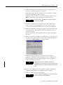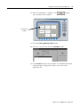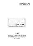
1
Modbus
Applications
For PanelView Plus and
PanelView Plus CE Terminals
2711P
User Manual
Important User Information
Solid state equipment has operational characteristics differing from those of
electromechanical equipment. Safety Guidelines for the Application,
Installation and Maintenance of Solid State Controls (publication SGI-1.1
available from your local Rockwell Automation sales office or online at
http://literature.rockwellautomation.com) describes some important
differences between solid state equipment and hard-wired electromechanical
devices. Because of this difference, and also because of the wide variety of
uses for solid state equipment, all persons responsible for applying this
equipment must satisfy themselves that each intended application of this
equipment is acceptable.
In no event will Rockwell Automation, Inc. be responsible or liable for
indirect or consequential damages resulting from the use or application of
this equipment.
The examples and diagrams in this manual are included solely for illustrative
purposes. Because of the many variables and requirements associated with
any particular installation, Rockwell Automation, Inc. cannot assume
responsibility or liability for actual use based on the examples and diagrams.
No patent liability is assumed by Rockwell Automation, Inc. with respect to
use of information, circuits, equipment, or software described in this manual.
Reproduction of the contents of this manual, in whole or in part, without
written permission of Rockwell Automation, Inc., is prohibited.
Throughout this manual, when necessary, we use notes to make you aware
of safety considerations.
WARNING
IMPORTANT
ATTENTION
Identifies information about practices or circumstances that can cause
an explosion in a hazardous environment, which may lead to personal
injury or death, property damage, or economic loss.
Identifies information that is critical for successful application and
understanding of the product.
Identifies information about practices or circumstances that can lead
to personal injury or death, property damage, or economic loss.
Attentions help you identify a hazard, avoid a hazard, and recognize
the consequence
SHOCK HAZARD
Labels may be on or inside the equipment, for example, a drive or
motor, to alert people that dangerous voltage may be present.
BURN HAZARD
Labels may be on or inside the equipment, for example, a drive or
motor, to alert people that surfaces may reach dangerous
temperatures.
Table of Contents
Preface
Topics Covered. . . . . . . . . . . . . . . . . . . . . . . . . . . . . . . . . . . 7
Software Requirements . . . . . . . . . . . . . . . . . . . . . . . . . . . . . 8
Additional Resources. . . . . . . . . . . . . . . . . . . . . . . . . . . . . . . 8
Chapter 1
Installing Software
Objectives. . . . . . . . . . . . . .
Install RSView Studio . . . . .
Install KEPServer Enterprise.
Firmware Upgrade Wizard. .
.
.
.
.
.
.
.
.
.
.
.
.
.
.
.
.
.
.
.
.
.
.
.
.
.
.
.
.
.
.
.
.
.
.
.
.
.
.
.
.
.
.
.
.
.
.
.
.
.
.
.
.
.
.
.
.
.
.
.
.
.
.
.
.
.
.
.
.
.
.
.
.
.
.
.
.
.
.
.
.
.
.
.
.
.
.
.
.
.
.
.
.
.
.
.
.
. 9
. 9
10
10
Objectives. . . . . . . . . . . . . . . . . . . . . . . . . . . . . . . . . .
Modbus Master/Slave . . . . . . . . . . . . . . . . . . . . . . . . .
Modbus (RTU) Serial . . . . . . . . . . . . . . . . . . . . . . .
Modbus Unsolicited Serial . . . . . . . . . . . . . . . . . . .
Modbus ASCII. . . . . . . . . . . . . . . . . . . . . . . . . . . . . . .
Modbus/TCP. . . . . . . . . . . . . . . . . . . . . . . . . . . . . . . .
Modbus Device Model . . . . . . . . . . . . . . . . . . . . . .
MailBox. . . . . . . . . . . . . . . . . . . . . . . . . . . . . . . . .
Guidelines for Developing Modbus Applications . . . . .
Create a Modbus Application . . . . . . . . . . . . . . . . .
Compile, Download and Run a Modbus application
.
.
.
.
.
.
.
.
.
.
.
.
.
.
.
.
.
.
.
.
.
.
.
.
.
.
.
.
.
.
.
.
.
.
.
.
.
.
.
.
.
.
.
.
11
11
11
11
13
13
13
13
14
14
14
Chapter 2
Modbus KEPServer Drivers
Chapter 3
Configuring KEPServer Drivers for Objectives. . . . . . . . . . . . . . . . . . . . . . . . . . . . . . . . . . . . . . 15
Create a Project File . . . . . . . . . . . . . . . . . . . . . . . . . . . . . . 15
Modbus
Select the Default Project File (.pfe) . . . .
Configure Drivers for Modbus Protocols.
Add a Channel. . . . . . . . . . . . . . . . .
Add A Device . . . . . . . . . . . . . . . . .
Create Tags. . . . . . . . . . . . . . . . . . . . . .
.
.
.
.
.
.
.
.
.
.
.
.
.
.
.
.
.
.
.
.
.
.
.
.
.
.
.
.
.
.
.
.
.
.
.
.
.
.
.
.
.
.
.
.
.
.
.
.
.
.
.
.
.
.
.
.
.
.
.
.
.
.
.
.
.
..
..
..
..
..
16
17
17
24
32
Chapter 4
Testing KEPServer
Communications
Objectives. . . . . . . . . . . . . . . . . . . . . . . . . . . . . . . . . . . . . . 35
Use the OPC Quick Client . . . . . . . . . . . . . . . . . . . . . . . . . . 35
Chapter 5
Making KEPServer Drivers and
Tags Available in RSView Studio
3
Objectives. . . . . . . . . . . . . . . . . . . . . . . . . . . . . . . . . . . . . . 37
Create an OPC Data Server . . . . . . . . . . . . . . . . . . . . . . . . . 37
Browse KEPServer Tags. . . . . . . . . . . . . . . . . . . . . . . . . . . . 39
Publication 2711P-UM002B-EN-P - March 2007
4
Table of Contents
Chapter 6
Installing KEPServer Drivers on
Terminal
Objectives. . . . . . . . . . . . . . . . . . . . . . . . . . . . . . . . . . . . .
Firmware Upgrade Wizard. . . . . . . . . . . . . . . . . . . . . . . . .
Preparing Terminal for Firmware Upgrade . . . . . . . . . .
Copy FUP Files to Development Computer . . . . . . . . . . . .
Upgrade Firmware using a Compact Flash Card . . . . . . . . .
Upgrade Firmware using a Network (Ethernet) Connection.
.
.
.
.
.
.
41
41
41
42
42
46
..
..
..
..
..
..
..
53
53
54
56
56
57
58
Chapter 7
Compiling, Downloading, and
Running Application
Objectives. . . . . . . . . . . . . . . . . . . . . .
Compile a Runtime Application File . . .
Download Application to Terminal . . .
Connect Terminal to Modbus Network.
Modbus Serial Cables . . . . . . . . . . .
Modbus Ethernet Cables. . . . . . . . .
Run Application . . . . . . . . . . . . . . . . .
.
.
.
.
.
.
.
.
.
.
.
.
.
.
.
.
.
.
.
.
.
.
.
.
.
.
.
.
.
.
.
.
.
.
.
.
.
.
.
.
.
.
.
.
.
.
.
.
.
.
.
.
.
.
.
.
.
.
.
.
.
.
.
.
.
.
.
.
.
.
.
.
.
.
.
.
.
.
.
.
.
.
.
.
.
.
.
.
.
.
.
.
.
.
.
.
.
.
Chapter 8
Troubleshooting
Objectives. . . . . . . . . . . . . . . . . . . . . . . . . . . . . . . . . . . . . . 59
Common Errors. . . . . . . . . . . . . . . . . . . . . . . . . . . . . . . . . . 59
Runtime Errors . . . . . . . . . . . . . . . . . . . . . . . . . . . . . . . . . . 59
Appendix A
Data Types
Appendix B
Modbus/TCP Address Definitions
Output Coils . . . . . . .
Input Coils . . . . . . . .
Internal Registers . . .
Holding Registers . . .
Mailbox Addressing. .
Instromet Addressing.
.
.
.
.
.
.
.
.
.
.
.
.
.
.
.
.
.
.
.
.
.
.
.
.
.
.
.
.
.
.
.
.
.
.
.
.
.
.
.
.
.
.
.
.
.
.
.
.
.
.
.
.
.
.
.
.
.
.
.
.
.
.
.
.
.
.
.
.
.
.
.
.
.
.
.
.
.
.
.
.
.
.
.
.
.
.
.
.
.
.
.
.
.
.
.
.
.
.
.
.
.
.
.
.
.
.
.
.
.
.
.
.
.
.
.
.
.
.
.
.
.
.
.
.
.
.
.
.
.
.
.
.
.
.
.
.
.
.
.
.
.
.
.
.
.
.
.
.
.
.
.
.
.
.
.
.
.
.
.
.
.
.
..
..
..
..
..
..
63
63
64
65
67
68
Appendix C
Modbus ASCII Address Definitions Output Coils . . . . . . . . . . . . . . . . . . . . . . . . . . . . . . . . . . . . 69
Input Coils . . . . . . . . . . . . . . . . . . . . . . . . . . . . . . . . . . . . . 69
Internal Registers . . . . . . . . . . . . . . . . . . . . . . . . . . . . . . . . 70
Holding Registers . . . . . . . . . . . . . . . . . . . . . . . . . . . . . . . . 71
Appendix D
Modbus Unsolicited Serial
Address Definitions
Publication 2711P-UM002B-EN-P - March 2007
Output Coils . . . .
Input Coils . . . . .
Internal Registers
Holding Registers
.
.
.
.
.
.
.
.
.
.
.
.
.
.
.
.
.
.
.
.
.
.
.
.
.
.
.
.
.
.
.
.
.
.
.
.
.
.
.
.
.
.
.
.
.
.
.
.
.
.
.
.
.
.
.
.
.
.
.
.
.
.
.
.
.
.
.
.
.
.
.
.
.
.
.
.
.
.
.
.
.
.
.
.
.
.
.
.
.
.
.
.
.
.
.
.
.
.
.
.
.
.
.
.
.
.
.
.
.
.
.
.
.
.
.
.
.
.
.
.
.
.
.
.
.
.
.
.
73
73
74
75
Table of Contents
5
Appendix E
Modbus (RTU) Serial Address
Definitions
Output Coils . . . . . . . . . . . . . . . . . . . . . . .
Input Coils . . . . . . . . . . . . . . . . . . . . . . . . .
Internal Registers . . . . . . . . . . . . . . . . . . . .
Holding Registers . . . . . . . . . . . . . . . . . . . .
Magnetek Address Descriptions . . . . . . . . . .
Elliott Flow Computer Address Descriptions .
Omni Address Descriptions . . . . . . . . . . . . .
Daniel S500 Address Descriptions . . . . . . . .
Index
Rockwell Automation Support . . . . . . . . . . . . . . . . . . . . . . . 93
Installation Assistance . . . . . . . . . . . . . . . . . . . . . . . . . . 93
New Product Satisfaction Return . . . . . . . . . . . . . . . . . . . 93
.
.
.
.
.
.
.
.
.
.
.
.
.
.
.
.
.
.
.
.
.
.
.
.
.
.
.
.
.
.
.
.
.
.
.
.
.
.
.
.
.
.
.
.
.
.
.
.
.
.
.
.
.
.
.
.
.
.
.
.
.
.
.
.
.
.
.
.
.
.
.
.
.
.
.
.
.
.
.
.
.
.
.
.
.
.
.
.
.
.
.
.
.
.
.
.
77
77
78
79
81
82
83
88
Publication 2711P-UM002B-EN-P - March 2007
6
Table of Contents
Publication 2711P-UM002B-EN-P - March 2007
Preface
For communication with controllers, RSView Machine Edition
products are configured with:
• RSLinx Enterprise for most Rockwell Automation networks or
• KEPServer Enterprise for RSView OPC servers.
The KEPServer OPC server expands PLC and device connectivity
options by incorporating 26 communication drivers for the PanelView
Plus and PanelView Plus CE platforms, and over 31 communication
drivers for RSView Machine Edition running on a desktop.
This guide will show you how to configure KEPServer drivers,
specifically Modbus drivers, for RSView ME applications that run on:
• PanelView Plus CE terminals,
• PanelView Plus terminals,
• or the Windows 2000/XP environment.
Using configured KEPServer drivers in your RSView ME application,
the terminals will be able to communicate with devices on a Modbus
network.
Topics Covered
• Chapter 1 Installing Software - Covers software installation for
RSView Studio, RSView Enterprise, KEPServer Enterprise and the
Firmware Upgrade Wizard.
• Chapter 2 Overview of Modbus Protocols - Gives an overview of
Modbus Master/Slave Protocol and each of the KEPServer
drivers for Modbus communication protocols.
• Chapter 3 Configuring KEPServer Drivers for Modbus - Shows
how to use KEPServer Enterprise software to configure
KEPServer drivers for Modbus protocols. For each driver, you
will create a channel, add a device, and create tags. The driver is
saved to a .pfe project file that you will set as the default project.
• Chapter 4 Testing KEPServer Communications - Shows how to
use the OPC Quick Client to test KEPServer communications for
the driver and tags created in Chapter 3.
• Chapter 5 Making KEPServer Driver and Tags Available in
RSView Studio - Shows how to create an OPC data server in
RSView Enterprise or RSView Studio. This server will allow you
to access the KEPServer driver and tags from your RSView ME
application.
• Chapter 6 Installing KEPServer Drivers on Terminal - Shows how
to use the Firmware Upgrade Wizard to install KEPServer drivers
on PanelView Plus/PanelView Plus CE terminals.
7
Publication 2711P-UM002B-EN-P - March 2007
8
• Chapter 7 Compiling, Downloading, and Running Application Shows how to compile a runtime .mer file, connect your
PanelView Plus/PanelView Plus CE terminal to a Modbus
network, download the .mer file to the terminal, and run the
application.
• Chapter 8 Troubleshooting - Covers common error types that
occur during runtime and how you can correct these errors.
Software Requirements
The following software must be installed on the development
desktop:
• RSView Studio 3.0, or later
• KEPServer Enterprise software
• Firmware Upgrade Wizard
Additional Resources
You might want to consult the following sources for additional
information:
• KEPServer Enterprise Software online help
• RSView Enterprise or RSView Studio online help
• PanelView Plus User Manual, publication no. 2711P-UM001
An electronic version of the PanelView Plus user manual is
available at:
http://literature.rockwellautomation.com
Publication 2711P-UM002B-EN-P - March 2007
Chapter
1
Installing Software
Objectives
To develop RSView ME applications, configure KEPServer drivers, and
use these drivers with applications that run on PanelView
Plus/PanelView Plus CE terminals, the following software must be
loaded on your development computer:
• RSView Studio for ME or RSView Enterprise
• KEPServer Enterprise
• Firmware Upgrade Wizard
Refer to the installation information provided with RSView Studio and
KEPServer Enterprise for the latest details on installation requirements.
Install RSView Studio
RSView Studio Enterprise or RSView Studio for Machine Edition
software is installed from:
• a CD or
• downloaded from the Rockwell Software website at
www.software.rockwell.com.
IMPORTANT
A current registered serial number is required to download
software from the Rockwell Software website.
The installation menu with instructions will appear when inserting the
CD into a computer or you can run setup.exe from the root directory.
9
Publication 2711P-UM002B-EN-P - March 2007
10
Installing Software
Install KEPServer
Enterprise
KEPServer Enterprise is used to:
• configure the KEPServer driver
• create tags
• test communications on the desktop.
KEPServer Enterprise is included with RSView Studio and can be
installed from:
• a CD or
• downloaded from the Rockwell Software web site at
www.software.rockwell.com.
KEPServer runs as a service and an icon will display in the toolbar.
IMPORTANT
A current registered serial number is required to download
software from the Rockwell Software website.
The software can be installed by running the setup.exe file from the
CD or downloaded version.
IMPORTANT
Firmware Upgrade Wizard
When installing KEPServer Enterprise, be sure to select the
Modbus drivers if you are not doing a full install.
The Firmware Upgrade Wizard is used to install KEPServer drivers and
upgrade firmware in the following devices:
• PanelView Plus
• PanelView Plus CE
The Firmware Upgrade Wizard is installed automatically with RSView
Studio.
The Firmware Upgrade (FUP) files with the KEPServer drivers is
available at http://support.rockwellautomation.com under
Downloads.
Publication 2711P-UM002B-EN-P - March 2007
Chapter
2
Modbus KEPServer Drivers
Objectives
This chapter provides an overview of MODBUS KEPServer drivers
available in the RSView Enterprise software.
• Modbus Master/Slave
– Modbus (RTU) Serial
– Modbus Unsolicited Serial
• Modbus ASCII
• Modbus/TCP
Modbus Master/Slave
A Modbus master/slave network provides a protocol for data transfer
and programming with a single RTU master and up to 247 slave
devices. A Modbus network links distributed devices with a central
computer terminal or controller for supervisory control and data
acquisition. Up to 247 nodes can be connected at data rates of up to
19,200 baud using media such as twisted pair cable, common carrier
phone lines, or microwave transmission. This network is commonly
used in SCADA application over large areas such as the water/waste
water and oil & gas industries.
Modbus (RTU) Serial
Modbus (RTU) Serial is the protocol for a master and includes RTS
support for radio modems. Supported devices include:
• Modbus compatible devices
• Elliott Flow Computer
• Magnetek GPD 515 Drive
• Omni Flow Computer
• Daniel S500 Flow Computer
• Dynamic Fluid Meter (DFM) SFC3
• Instromet
Modbus Unsolicited Serial
Modbus Unsolicited Serial simulates up to 247 Modbus slave devices.
Supported devices include Modbus compatible devices.
11
Publication 2711P-UM002B-EN-P - March 2007
12
Modbus KEPServer Drivers
Modbus Master/Slave Networks
See Chapter 7 for cable information.
Direct Connection
PanelView Plus
(Modbus Serial or
Unsolicited Serial Driver)
RS-232/RS-485 Converter(1)
(1)
Controller (Master or Slave)
1761-NET-AIC or Comparable Device
Master/Slave Network (Multiple Slave Terminals Connect to one Master Controller)
(3) PanelView Plus Slave Devices
Each uses Modbus Unsolicited Serial Driver
PanelView Plus
PanelView Plus
PanelView Plus
Master Controller
RS-232/RS-485
Converters
RS-232/RS-485
Converters
(1) PanelView Plus Master Device
Uses the Modbus Serial Driver
PanelView Plus
Modbus Device
RS-232/RS-485
Converters
Modbus Device
RS-232/RS-485
Converters
Modbus Device
RS-232/RS-485
Converters
Modem Connection
PanelView Plus
(2) PanelView Plus Slave Devices Modbus
Each uses the Modbus Unsolicited Serial Driver
Master Controller
Modems
PanelView Plus
Publication 2711P-UM002B-EN-P - March 2007
Modbus KEPServer Drivers
13
Modbus ASCII
Modbus ASCII protocol is typically used to connect to other ASCII
devices that support the Modbus ASCII protocol. KEPServer support
includes:
• Modbus ASCII compatible devices
• Flow Computers using Daniels/Omni/Elliott register addressing
Modbus/TCP
Modbus/TCP is a Modbus messaging protocol over Ethernet TCP/IP
and is intended for supervision and control of automation equipment.
The most common use of this protocol is for Ethernet attachment of
PLCs, I/O modules, and gateways to other simple field buses or I/O
networks.
The Modbus/TCP KEPServer driver supports Modbus and Mailbox
device models.
Modbus Device Model
The most common Modbus device model is where the driver connects
to physical devices (e.g. Modicon TSX Quantum, other Modbus Open
Ethernet compatible devices) and acts as a device on the network
with a device ID equivalent to the machine's IP address. The driver
accepts any unsolicited commands it receives and attempts to process
them as if it were another PLC.
MailBox
The Mailbox model determines the manner unsolicited requests are
handled. By defining a mailbox device, the driver does not act like a
PLC on the network (as described above). Instead, it acts as a storage
area for each and every mailbox device defined. When the driver
receives an unsolicited command, the driver detects the IP address the
message came from and places the data in the storage area allocated
for the device. If the message comes from a device with an IP address
that has not been defined as a mailbox device, the message is not
processed. Any client application that reads/writes to this type of
device, reads/writes to the storage area contained in the driver, not
the physical device.
Publication 2711P-UM002B-EN-P - March 2007
14
Modbus KEPServer Drivers
Refer to the MSTR instruction in your Modicon documentation for
details on sending unsolicited requests to the Modbus Ethernet driver.
PanelView Plus
PanelView Plus
Ethernet Ethernet
Switch Switch
Master Controller
PanelView Plus
Guidelines for Developing
Modbus Applications
The section provides general guidelines for creating and running
Modbus applications on PanelView Plus/PanelView Plus CE terminals.
Create a Modbus Application
General Steps
Description
Reference
Step 1
Create a .pfe project file in KEPServer
Enterprise.
Chapter 3
Step 2
Configure a KEPServer Modbus Driver. Add a
channel and device to the project file.
Chapter 3
Step 3
Enter application tags.
Chapter 3
Step 4
Set your .pfe file as the default project file.
Chapter 3
Step 5
Test KEPServer communications to verify your
project file and tags.
Chapter 4
Step 6
Create an OPC Data Server to make your tags
available in RSView Studio.
Chapter 5
Compile, Download and Run a Modbus application
Publication 2711P-UM002B-EN-P - March 2007
General Steps
Description
Reference
Step 1
Create a firmware upgrade card that contains
the KEPWare driver and upgrade the terminal.
Chapter 6
Step 2
Compile the RSView .mer application.
Chapter 7
Step 3
Download the .mer runtime file to terminal.
Chapter 7
Step 4
Connect the terminal to the Modbus network.
Chapter 7
Step 5
Run the application.
Chapter 7
Chapter
3
Configuring KEPServer Drivers for Modbus
Objectives
This chapter shows how to use KEPServer Enterprise software to
configure KEPServer drivers for Modbus protocols including Ethernet
TCP/IP, RTU Serial, Unsolicited Serial, and ASCII Serial. You will:
• create a project (.pfe) for the drivers
• set the project file as the default project
For each Modbus driver in your project file, you will:
• add a channel
• add a device (or controller)
• create tags
Create a Project File
The first thing you need to do is create a project file.
1. Double-click the KEPServer Enterprise icon in the Systray to
open the default project window below.
15
Publication 2711P-UM002B-EN-P - March 2007
16
Configuring KEPServer Drivers for Modbus
2. Create a new KEPServer project (.pfe) file. From the menu,
select File>Save As and save the project as a .pfe file.
Select the Default Project
File (.pfe)
The steps in this section ensure that the correct project file is used in
your RSView Studio application.
When RSView Studio creates a runtime application and the application
contains the KEPware OPC server, RSView Studio will merge the
KEPware project file (.pfe) into the runtime file (.mer). The project file
that RSView Studio uses is defined by the Default project field in the
General tab of the Tools>Options menu in KEPware Server
Enterprise.
TIP
This may not be the current configuration running in
KEPware Server Enterprise. If you are testing the
application on a PC, make sure the project name in
the title bar of KEPware Server Enterprise matches
the Project default field.
1. From the Menu bar, select Tools>Options…
2. On the General tab, click the
project textbox.
button next to the Default
3. Select the desired .pfe file and click the
Publication 2711P-UM002B-EN-P - March 2007
button.
Configuring KEPServer Drivers for Modbus
17
You should now see the following:
4. Click the
the default.
TIP
Configure Drivers for
Modbus Protocols
button and OK to accept the new project as
The KEPServer configuration is not archived with the
RSView Studio application backup (.apa) file. If you
need to reuse the project configuration file on
another computer, copy the .pfe file.
This section shows how to configure KEPServer drivers that will allow
a PanelView Plus/PanelView Plus CE terminal to communicate on a
Modbus network.
Add a Channel
The first step in communicating to any device using the KEPServer
software is to create a channel. A channel describes the protocol and
driver properties used for communication. While a single channel can
be used to communicate to multiple devices, separate channels must
be defined for each unique driver to be used. Only one project
configuration file can run at a time, but it may contain multiple
channels and devices.
Step 1 - Add a New Channel
Click on the New Channel icon or right-click anywhere in the left
pane. This will bring up the new channel wizard.
Step 2 - Enter a Channel Name
Enter a unique name for the channel.
Publication 2711P-UM002B-EN-P - March 2007
18
Configuring KEPServer Drivers for Modbus
Step 3 -Select a Device Driver
Select a driver from the drop down list. The table below lists the
correct driver for each Modbus protocol.
For this Protocol:
Select this Driver:
Modbus/TCP
Modbus Ethernet
Modbus RTU Serial (Master)
Modbus Serial
Modbus Unsolicited Serial (Slave)
Modbus Unsolicited Serial
Modbus ASCII
Modbus ASCII Serial
Step 4 - Select a Network Adapter (for Modbus/TCP only)
The Network Adapter selection left allows you to select a specific NIC
card based on either the NIC name or its currently assigned IP
address. The list of available NICs will include either unique NIC cards
or NICs that have multiple IP addresses assigned to them.
Additionally, the selection will display any WAN connections you may
have active such as a dialup connection.
For PanelView Plus/PanelView Plus CE, select Default and click Next.
Step 5 - Enter Communication Settings (doesn’t apply to Modbus/TCP)
In the New Channel - Communications dialog, make sure the Modicon
controller configuration settings match those in slave controllers or
devices.
Publication 2711P-UM002B-EN-P - March 2007
Parameter
Selections
Recommended
Data Bits
5, 6, 7, 8
8
Stop Bits
1, 2
1
Parity
None, Even, Odd
Even
Baud
300 to 256000
9600 or 19200
Configuring KEPServer Drivers for Modbus
19
Modbus RTU Serial
Modbus Unsolicited Serial
Publication 2711P-UM002B-EN-P - March 2007
20
Configuring KEPServer Drivers for Modbus
Modbus ASCII
Step 6 - Set the Optimization Method for Data Requests
The New Channel - Write Optimization dialog sets the optimization
method for data requests. Select the best optimization for your
application and click Next.
For more information on KEPServer read and write optimization
options refer to the online Driver help.
Applies to all Modbus protocols
Publication 2711P-UM002B-EN-P - March 2007
Configuring KEPServer Drivers for Modbus
21
Step 7 -Select Socket Usage (Applies to Modbus/TCP only)
The New Channel - Socket Usage dialog controls how the Modbus
Ethernet driver will utilize Windows sockets when establishing a
connection to the target device. For a normal Modbus Ethernet
enabled device, the default Use Multiple Sockets for device
connection (checked) mode of operation is designed to give the best
performance from the driver.
Normally, the Modbus Ethernet driver will use a Windows socket for
each device on the network. When using a new socket connection for
each device, the Modbus Ethernet driver maintains that socket as an
active connection. Normally this provides a very high level of
performance since the driver does not need to reestablish a
connection each time it needs to read or write data to a given device.
For more information on using Sockets in a Modbus RTU bridge
application, refer to the online help.
Click Next.
Publication 2711P-UM002B-EN-P - March 2007
22
Configuring KEPServer Drivers for Modbus
Step 8 - View and Verify Channel Summary
The New Channel - Summary dialog provides a summary of the new
channel settings. Verify the settings below and click Finish.
Modbus/TCP
Modbus RTU Serial
Publication 2711P-UM002B-EN-P - March 2007
Configuring KEPServer Drivers for Modbus
23
Modbus Unsolicited Serial
Modbus ASCII Serial
TIP
The red X next to the channel name will disappear
when a destination device is added under this driver.
Step 9 - Save Project File
From the Menu bar, select File>Save or click the Save
button.
Publication 2711P-UM002B-EN-P - March 2007
24
Configuring KEPServer Drivers for Modbus
Add A Device
Now that a new channel is defined, you need to add a new device to
the channel. In most cases, selecting the default settings will allow
you to quickly configure and connect to a device.
Step 1 - Add a Device
Add a device by clicking on the Click to add a device hypertext or the
New Device icon. This will bring up the new device wizard. Here
you’ll add the information pertinent to the controller that you are
going to communicate with.
Step 2 - Enter a Device Name
In the New Device - Name dialog, enter a device name that will help
you identify the device later and click Next. In most cases, the device
will be a logic controller.
Step 3 - Select a Device Model
If the device you are defining supports more than one model, select a
model that best describes the device.
Publication 2711P-UM002B-EN-P - March 2007
For this Protocol:
Most Common Model:
MODBIS/TCP
Modbus
Modbus RTU Serial
Modbus
Modbus Unsolicited Serial
N/A
Modbus ASCII
Modbus ASCII
Configuring KEPServer Drivers for Modbus
25
Step 4 - Select a Device ID
The device you are defining may be multidropped as part of a
network of devices. To communicate with the device, it must be
assigned a unique ID.
In the New Device - ID dialog, enter a unique Device ID (decimal
address) to identify the controller on the network. Enter the Device ID
and click Next.
For this Protocol:
Device ID Range
Data Format
Modbus/TCP (1)
xxx.xxx.xxx.xxx
IP Address
ModbusModbus RTU Serial
0 - 255
Decimal
Modbus Unsolicited Serial
1 - 247
Decimal
Modbus ASCII
1 - 247
Decimal
(1)
For master/slave communications, add a fifth octet to the IP address. Refer to your KEPWare
documentation for more details on Modbus/TCP master/slave communications.
Step 5 - Enter Device Communication Parameters
(Doesn’t apply to Modbus Unsolicited Serial Protocol)
In the New Device - Communication Parameters dialog, accept the
default communication parameters by clicking Next.
Publication 2711P-UM002B-EN-P - March 2007
26
Configuring KEPServer Drivers for Modbus
Step 6 - Configure Tag Database Options
(Doesn’t apply to Unsolicited Serial or ASCII Protocols)
In the New Device - Database Creation dialog, click Next to accept
the default tag database configuration options.
The automatic OPC tag database generation features of the server
have been designed to make the setup of your OPC application a Plug
and Play operation. For communication drivers that support this
feature, you can configure them to automatically build a list of OPC
tags within the server that correspond to device specific data. The
automatically generated OPC tags can then be browsed from your
OPC client.
Publication 2711P-UM002B-EN-P - March 2007
Configuring KEPServer Drivers for Modbus
27
Step 7 - Enter Device Settings
In the New Device - Settings dialog, accept the default settings by
clicking Next
Modbus/TCP
Modbus RTU Serial
Publication 2711P-UM002B-EN-P - March 2007
28
Configuring KEPServer Drivers for Modbus
Modbus Unsolicited Serial and Modbus ASCII
Step 8 - Set the Block Size for Reading Data from Device
(Doesn’t apply to Unsolicited Serial Protocol)
The New Device - Block Sizes dialog sets the largest block size for
reading I/O (coils) and data tables (Registers). Click Next.
Modbus/TCP, Modbus RTU Serial, Modbus ASCII
Publication 2711P-UM002B-EN-P - March 2007
Configuring KEPServer Drivers for Modbus
29
Reasons to Change the Default Block Sizes include:
• The device may not support block read/write operations of
the default size. Smaller Modicon PLCs and non-Modicon
devices may not support the maximum data transfer lengths
supported by the Modbus Ethernet network.
• The device may contain non-contiguous addresses. If this is
the case and the driver attempts to read a block of data that
encompasses undefined memory, the device will probably
reject the request.
Step 9 - Set Location of the Variable Import File
The New Device - Variable Import Settings dialog sets the location of
the Concept or ProWORX variable import file the driver will use when
the automatic tag database generation feature is enabled for this
device. Refer to the KEPServer Enterprise online help for details on
how to use this feature.
Publication 2711P-UM002B-EN-P - March 2007
30
Configuring KEPServer Drivers for Modbus
Step 10 - View and Verify the Device Summary Information
The New Device - Summary dialog provides a summary of the new
device settings. Verify the information and click Finish.
Modbus/TCP
Modbus RTU Serial
Publication 2711P-UM002B-EN-P - March 2007
Configuring KEPServer Drivers for Modbus
31
Modbus Unsolicited Serial
Modbus ASCII
Step 11 - Save Project File
From the Menu bar, select File>Save or click the Save
button.
Publication 2711P-UM002B-EN-P - March 2007
32
Configuring KEPServer Drivers for Modbus
Create Tags
With a channel and device defined, you are ready to create tags
within the KEPServer software. These tags are used to link to the
controller addresses. The procedure is similar to creating an HMI tag
database. For details on valid data types and addressing, see
Appendices A - E.
1. In the right hand pane, click on the Click to add a static tag text.
Or right-click on a device (such as the Momentum_IEC) in the
left hand pane and select New Tag…
The Tag Properties dialog opens.
2. Enter the tag name and address along with a description as
shown in the following dialogs.
TIP
Publication 2711P-UM002B-EN-P - March 2007
Clickon ? next to the Address field for a list of
valid addresses.
Configuring KEPServer Drivers for Modbus
33
Replace the ’xx with your table number.
For example, the Address for table #1
would be 40101.
KEPServer allows you to validate the address based on the device you
will be talking to. Your project configuration should now list the tags
in the right pane.
3. From the Menu bar, select File>Save or click the Save
button.
Publication 2711P-UM002B-EN-P - March 2007
34
Configuring KEPServer Drivers for Modbus
Publication 2711P-UM002B-EN-P - March 2007
Chapter
4
Testing KEPServer Communications
Objectives
This chapter shows how to test KEPServer communications on a
development computer to verify your project configuration and tags.
Use the OPC Quick Client
Included with the KEPServer server installation is a simple tool for
testing OPC tags called the OPC Quick Client. When you create a
new KEPServer configuration, there are several system and
communications tags that are also created. In this section, you'll verify
communication with the tags you’ve created before incorporating
them into an HMI project.
1. Select Tools>Launch OPC Quick Client from the main menu. Or
click on the OPC Quick Client
icon.
2. Highlight the name of the device that you plan to test in the left
pane. This will display the tags that you have created in the right
pane.
3. Right-click the tag in the right pane that you plan to test, and
select Synchronous Write.
35
Publication 2711P-UM002B-EN-P - March 2007
36
Testing KEPServer Communications
The resulting window not only allows you to write new data to
the controller, but it also displays the current value of the tag.
Publication 2711P-UM002B-EN-P - March 2007
Chapter
5
Making KEPServer Drivers and Tags
Available in RSView Studio
Objectives
Now that you’ve configured and tested KEPServer communications,
you are ready to make the KEPServer driver and tags available in
RSView Studio. This chapter will show you how to add an OPC data
server to the RSView Studio project.
Create an OPC Data Server
KEPServer is an OPC data server. You need to add this server to the
RSView Studio project.
1. Open RSView Enterprise or RSView Studio for Machine Edition
from the development computer.
2. Open your application.
3. In the Application Explorer pane (left), right-click on the
application name at the root of the tree view and select New
Data Server>OPC…
4. Click the
textbox.
37
button next to the OPC Server Name
Publication 2711P-UM002B-EN-P - March 2007
38
Making KEPServer Drivers and Tags Available in RSView Studio
5. Select KEPServerEnterprise and click OK.
6. Enter a name for the KEPServer driver and click OK.
Informational messages appear at the bottom of your RSView
Studio window indicating that the Server has started and is
available on the computer.
Any tags created earlier in the KEPServer software are now available
for the HMI using the standard RSView Studio tag browser.
TIP
Publication 2711P-UM002B-EN-P - March 2007
Remove all serial drivers from the RSLinx Enterprise
Communication Setup that would conflict with the port
configured for Modbus.
Making KEPServer Drivers and Tags Available in RSView Studio
39
Browse KEPServer Tags
TIP
For additional information on working with tags, see Chapter 6
of the RSView Machine Edition User’s Guide (ViewME-UM003)
available under the RSView Studio help menu.
1. Double click or right-click on an object to open its Properties
dialog.
2. On the Connections tab, click the Value's
the FactoryTalk Tag Browser.
button to open
3. Right-click on the heading in the left pane and select Refresh All
Folders to obtain the list of tags in the KEPServer data server.
4. Drill down and select the tags from the folder you created.
This is the Channel name
created in KEPServer.
This is the Device name
created in KEPServer.
5. Click OK to close the window.
Publication 2711P-UM002B-EN-P - March 2007
40
Making KEPServer Drivers and Tags Available in RSView Studio
Publication 2711P-UM002B-EN-P - March 2007
Chapter
6
Installing KEPServer Drivers on Terminal
Objectives
If you plan to run the Machine Edition project on a PanelView Plus or
PanelView Plus CE terminal, the corresponding CE-based KEPServer
components must be installed. This chapter will show you how to use
the Firmware Upgrade Wizard (FUW) utility to install the KEPServer
drivers on the terminals.
Firmware Upgrade Wizard
The Firmware Upgrade Wizard (FUW) will add the necessary
KEPServer components to the terminal firmware. You can:
• create a firmware upgrade card (compact flash card) which you
then load in the card slot of terminal to upgrade firmware.
• upgrade firmware in a terminal that is connected to your
desktop computer using a Serial, Ethernet, or Network
connection via RSLinx Enterprise (for supported protocols).
The Firmware Upgrade Wizard is available in RSView Studio. Refer to
the FUW Help for additional information.
Preparing Terminal for Firmware Upgrade
Before starting the Firmware Upgrade Wizard, follow the steps below
to prepare the terminal for a successful upgrade.
1. Backup all .MER files on the terminal to an external storage card
or network.
2. Delete all applications on the terminal.
3. Record any Ethernet communication settings, such as IP address,
subnet masks, and gateways by selecting Terminal
Settings>Network and Communications>Network
Connections>Network Adapters>IP Address.
4. Disable the Auto-start feature on the terminal by selecting
Startup Options>RSView ME Station Startup and select Go to
Configuration Mode.
5. Reset the terminal.
41
Publication 2711P-UM002B-EN-P - March 2007
42
Installing KEPServer Drivers on Terminal
Copy FUP Files to
Development Computer
Download the Firmware Upgrade (FUP) files with the KEPServer
drivers to your development computer before using the FUW.
The FUP files are available on the Firmware Upgrade Media Kit (Cat.
No. 2711P-RU31O) which you can order through your local
Allen-Bradley distributor. Run the *.exe file to unzip the files. Unzip
the files to this directory:
Documents and Settings\All User Documents\RSView Enterprise\ME\Firmware Upgrade
The Firmware Upgrade Wizard is available at
http://.support.rockwellautomation.com under Downloads.
TIP
Upgrade Firmware using a
Compact Flash Card
This section shows how to upgrade firmware in a PanelView Plus
terminal using a Compact Flash Card. This is a two step-process. First,
you create a firmware upgrade card with the necessary firmware files.
Second, you load this card in the terminal to upgrade the firmware.
1. Creating Firmware Upgrade Card
1. Start the Firmware Upgrade Wizard. Select Start>Rockwell
Software>RSView Enterprise>Firmware Upgrade Wizard.
2. Select Create firmware upgrade card.
• In the Firmware card location text box, select the destination for
the compact flash files (folder on the hard drive or physical
location of the compact flash card, e.g., E:\).
• From the Existing terminal list, select the type of PanelView Plus
terminal you are upgrading, then press Next.
TIP
Publication 2711P-UM002B-EN-P - March 2007
To add a KEPWare driver to a PanelView Plus 400/600
terminal, use a compact flash card.
Installing KEPServer Drivers on Terminal
43
3. From the Firmware source folder list, select the location of the
firmware files. The default location is C:\Program
Files\Rockwell Software\RSView Enterprise\FUPs.
From the Upgrade firmware version list, select the version of the
firmware you want to upgrade to, then press Next.
4. Select the appropriate KEPServer drivers and press Next. If the
selected FUP file does not support the KEPServer drivers, this
dialog will not appear.
IMPORTANT
Each driver consumes 150Kbytes to 250Kbytes of disk-on-chip
memory space. Only install drivers to be used on the Windows
CE terminals. You can always add others drivers later if needed.
Publication 2711P-UM002B-EN-P - March 2007
44
Installing KEPServer Drivers on Terminal
5. Select Finish to copy the firmware source files to the location
specified in step 2.
TIP
If the files were created in a separate folder on a local
hard drive, copy the files to the root directory of the
compact flash card.
2. Upgrade Firmware in Terminal using Firmware Upgrade Card
1. Insert the compact flash card into the card slot of a powered
PanelView Plus terminal. A dialog appears indicating the
firmware upgrade is about to occur.
2. Press Upgrade to begin the firmware upgrade.
IMPORTANT
Publication 2711P-UM002B-EN-P - March 2007
Do NOT remove the compact flash card while the upgrade is in
process.
Installing KEPServer Drivers on Terminal
45
3. If other PanelView Plus terminals exist on the same Ethernet
network, the following error may display:
Error registering name on network (may be duplicate). Change
in system Control Panel and try again.
Ignore this error. It will be corrected during the upgrade. Press
OK to acknowledge error and wait for terminal to reset.
TIP
If a USB mouse is available you can acknowledge this
error by selecting OK.
4. On touch or touch/screen terminals, you must calibrate the
touch screen by selecting pointers in all four corners of the
screen and pressing the middle of the screen when prompted.
5. Ignore the following message if it appears. It means RSView ME
is being installed. Do not touch the two buttons that appear
with this message.
Machine edition may be corrupted. Do you want to download
firmware?
6. When the upgrade is complete, a dialog appears requesting you
to remove the compact flash card from the card slot. Remove the
card and press F8 or Exit to reset the terminal.
7. Communication settings are cleared when the terminal is
upgraded. If Ethernet communications is used, reconfigure the
Ethernet communication settings using the values recorded
when preparing the terminal.
TIP
Kepware drivers were installed on terminal. On
PanelView Plus CE terminals, you can go to the Storage
Card/KEPServer/Drivers folder to verify that the driver dll
exists.
8. Replace the .MER files that you backed up before starting the
upgrade or download a new .MER file to the terminal.
9. Load the .MER file and run the project.
TIP
You can configure your application to start automatically
on power cycle under Startup Options.
Publication 2711P-UM002B-EN-P - March 2007
46
Installing KEPServer Drivers on Terminal
Upgrade Firmware using a
Network (Ethernet)
Connection
You can upgrade the firmware in a terminal that is connected to a
desktop computer using a Serial, Ethernet or Network (using RSLinx
Enterprise) connection.
• Network connection requires RSLinx Enterprise where you
select the terminal on an existing network.
• Serial connection requires a RAS connection to be set up on
computer. During the RAS setup, you select the COM port.
• Ethernet connection requires that you enter the terminal’s IP
Address.
Both the Serial and Ethernet connection requires the PanelView Plus
File Transfer Utility running on the terminal and should only be used
when other methods fail.
This section shows how to upgrade firmware in a PanelView Plus
terminal using a Network connection via Ethernet communications.
1. Start the Firmware Upgrade Wizard. Select Start>Rockwell
Software>RSView Enterprise>Firmware Upgrade Wizard.
Publication 2711P-UM002B-EN-P - March 2007
Installing KEPServer Drivers on Terminal
47
2. Select Upgrade firmware on terminal and press OK.
3. Select Network connection and press Next.
Use the Ethernet and Serial connections only if the firmware
upgrade is unsuccessful.
4. Locate the PanelView Plus terminal on your Ethernet network
via its IP address.
Skip to Step 6 if you found the terminal. If you do not see the
terminal, right click on the Ethernet driver and add the device to
the browse tree.
Publication 2711P-UM002B-EN-P - March 2007
48
Installing KEPServer Drivers on Terminal
5. Double-click on EthernetIP Devices. Select the appropriate
terminal and press OK.
PanelView Plus CE 700
PanelView Plus CE 1000
PanelView Plus CE 1250
6. Enter the IP address for the terminal and press OK.
7. Select the terminal to be upgraded and press OK.
Publication 2711P-UM002B-EN-P - March 2007
Installing KEPServer Drivers on Terminal
49
8. From the Firmware source folder text box, select the location of
the firmware files. The default location is C:\Program
Files\Rockwell Software\RSView Enterprise\FUPs.
From the Upgrade firmware version list, select the version of the
firmware you want to upgrade to, then select Next.
PanelView Plus 700
9. Select the appropriate KEPServer drivers and select Next. If the
selected FUP file does not support the KEPServer drivers, this
dialog will not appear.
IMPORTANT
Each driver consumes 150Kbytes to 250Kbytes of disk-on-chip
memory space. Only install drivers to be used on the Windows
CE terminals. You can always add others drivers later if needed.
Publication 2711P-UM002B-EN-P - March 2007
50
Installing KEPServer Drivers on Terminal
10. Press Finish to start the upgrade.
11. Press Yes to continue the upgrade process. If the terminal was
properly prepared for the upgrade, no applications should be
running.
12. Firmware files are downloaded to the terminal. This may take
several minutes to 15 minutes. When the download is complete,
press OK to reset the terminal.
If other PanelView Plus terminals exist on the same Ethernet
network, the following error may display:
Error registering name on network (may be duplicate). Change
in system Control Panel and try again.
Ignore this error. It will be corrected during the upgrade. Press
OK to acknowledge error and wait for terminal to reset.
TIP
Publication 2711P-UM002B-EN-P - March 2007
If a USB mouse is available you can acknowledge the
error by selecting OK.
Installing KEPServer Drivers on Terminal
51
13. On touch or touch/screen terminals, you must calibrate the
touch screen by selecting pointers in all four corners of the
screen and pressing the middle of the screen when prompted.
14. Ignore the following message if it appears. It means RSView ME
is being installed. Do not touch the two buttons that appear with
the message.
Machine edition may be corrupted. Do you want to download
firmware?
15. Communication settings are cleared when the terminal is
upgraded. If Ethernet communications is used, reconfigure the
Ethernet communication settings using the values recorded
when preparing the terminal.
16. Replace the .MER files that you backed up before starting the
upgrade or download the new .MER files to the terminal.
17. Load the .MER file and run the project.
TIP
You can configure your application to start automatically
on power cycle under Startup Options.
Publication 2711P-UM002B-EN-P - March 2007
52
Installing KEPServer Drivers on Terminal
Publication 2711P-UM002B-EN-P - March 2007
Chapter
7
Compiling, Downloading, and Running
Application
Objectives
This chapter shows how to:
• compile a runtime RSView ME application file
• download and load application on terminal.
• connect terminal to a Modbus network
• run application.
Compile a Runtime
Application File
You are now ready to build the Machine Edition runtime (.mer) file to
be downloaded to a PanelView Plus/PanelView Plus CE terminal.
TIP
B
Before compiling the .mer file, verify that the correct .pfe
project file is selected. See page 16.
1. From the menu bar, select Application>Create Runtime
Application…
2. Save the project to the default Runtime folder location on the
hard drive. Enter the filename and click
After a few minutes, you should have an .mer project ready to
download to the terminal. The KEPServer .pfe project file
created in Chapter 3 is merged into the .mer file.
53
Publication 2711P-UM002B-EN-P - March 2007
54
Compiling, Downloading, and Running Application
Download Application to
Terminal
Typically, downloading an application to a terminal is accomplished
using the RSLinx Enterprise File Transfer Utility. You can download an
application using a Compact Flash card, a serial connection, or an
Ethernet connection. Refer to the RSView Machine Edition User
Manual (ViewME-UM003).
1. From the menu bar, select Tools>Transfer Utility…
2. On the Download tab, click the
button.
3. Select the .mer file and click
You should see the following dialog.
4. Select the target PanelView Plus using the Ethernet browsing
capability of RSLinx Enterprise. Right-click on the Ethernet,
AB_ETH-1 driver and select Start Browsing.
5. Highlight your PanelView Plus or PanelView Plus CE terminal
and click
Publication 2711P-UM002B-EN-P - March 2007
Compiling, Downloading, and Running Application
6. When the download is complete, click
55
and turn
your attention to the terminal.
Load Application
[F1] button
7. Click the Load Application [F1] Button.
8. Select the .mer file and click the Load [F2] button.
9. Click Yes [F7] to replace the terminal's current RSLinx Enterprise
communication configuration with the one stored in the
application file.
Publication 2711P-UM002B-EN-P - March 2007
56
Compiling, Downloading, and Running Application
Connect Terminal to
Modbus Network
Before running your application, you need to connect the PanelView
Plus/PanelView Plus CE terminal to a Modbus network using either:
• Modbus serial cables or
• Modbus Ethernet cables
Modbus Serial Cables
The serial port on a PanelView Plus/PanelView Plus CE terminal is
different than a desktop computer. Typically, you just need to add a
null modem adapter to a cable that works with a desktop computer.
To create a cable specifically for the PanelView Plus/PanelView Plus
CE, use the cable descriptions in this section for Modbus Serial
KEPServer drivers (RTU Serial, Unsolicited Serial, ASCII Serial).
Terminal to Controller 9-pin/25-pin/8-pin Port
Modbus Controller or
Desktop PC
25-pin
9-pin(1)
PanelView Plus RS-232 Port
9-pin DCE
RXD
2
3
4
3
TXD
3
2
7
4
DTR
4
20
5
COM
5
7
6
DSR
6
6
7
RTS
7
4
8
CTS
8
5
Chassis Gnd
(1)
The 2711-NC13, 2711-NC14, or 2706-NC13 cables have a 9-pin D-Shell connector.
(2)
The 2711-NC21 or 2711-NC22 have an 8-pin Mini DIN connector.
Terminal to Controller with an RJ45 Port
Terminal
DB-9 (male)
2 RD
3 TD
5 SG
Publication 2711P-UM002B-EN-P - March 2007
8-pin DIN(2)
1
2
9
Connector Shell
Hood
MicroLogix/ DNI
Shield
RJ-45 Connector
(male)
1
2
3
4
5
7
6
8
2
Compiling, Downloading, and Running Application
57
Null Modem Cable
To construct a null modem cable, refer to the following pinout:
Terminal
Controller
9-pin
25-pin
9-pin
3
3
3
2
2
2
5
7
5
1
8
1
4
20
4
6
6
6
8
5
8
7
4
7
Modbus Ethernet Cables
The RJ45 connector pinout for the PanelView Plus or VersaView
Terminal is shown below.
Connector
Pin
RJ45
Connector
1
TD+
2
TD-
3
RD+
4
NC
5
NC
6
RD-
7
NC
8
NC
8
1
Shield Connection
Pin Name
Chassis Gnd
Use point-to-point, 10/100Base-T cables with cross over pin-outs
(such as 2711P-CBL-EX04) when connecting the Ethernet port on the
PanelView Plus directly to a logic controller’s Ethernet port or a
computer 10/100Base-T port. Use standard Ethernet cables when
connecting to a switch or hub.
Publication 2711P-UM002B-EN-P - March 2007
58
Compiling, Downloading, and Running Application
Run Application
Now that your PanelView Plus/PanelView Plus CE terminal contains
the loaded application and is connected to a Modbus network, you
can run the application.
1. Click the Run Application [F2] button to launch application.
Load Application
[F2] button
Publication 2711P-UM002B-EN-P - March 2007
Chapter
8
Troubleshooting
Objectives
This chapter lists common errors that occur during application
development as well as errors that occur during runtime.
To diagnose error messages that are generated while developing the
KEPServer driver, refer to the KEPServer online help for the
appropriate driver and refer to the error description.
Common Errors
Some of the most common errors made during application
development are listed below:
• The .mer file was compiled with the wrong .pfe file. See page 16
for details on setting the default project file.
• The KEPServer driver was not downloaded to the terminal. On
PanelView Plus CE terminals, you can verify that the driver is in
the Storage card/KEPServer/drivers folder.
• The wrong serial cable is connected to the PanelView Plus or
PanelView Plus CE terminal. Refer to Chapter 7.
Runtime Errors
The table below lists errors that may occur during runtime. Possible
causes and solutions are provided for each error.
Error
Error Type
Device ’<device name> is not
responding
Serious
Possible Cause
1. The connection between the device and the
terminal is broken.
2. The communication parameters for the
connection are incorrect.
Solution
1. Verify the cabling between the terminal and
the device. The serial pinout for the
PanelView Plus/PanelView Plus CE terminal
is different than a computer.
2. Verify that the specified communi- cation
parameters match those of the device.
3. The named device may have been assigned
an incorrect network ID.
Unable to write to ’<address>’
on device ’<device name>’
Serious
3. Verify that the network ID given to the
named device matches that of the actual
device.
1. The named device may not be connected to
the network.
1. Check the PLC network connections.
2. The named device may have been assigned
an incorrect Network ID.
2. Verify that the network ID given to the
named device matches that of the actual
device.
3. The named device is not responding to write
requests.
4. The address does not exist in the PLC.
59
Publication 2711P-UM002B-EN-P - March 2007
60
Troubleshooting
Error
Error Type
Possible Cause
Solution
Bad address in block [x to y] on
device ’<device name>’
Fatal
addresses
failing in this
block
This error is reported when the driver attempts
to read a location in a PLC that does not exist.
For example, in a PLC that only has holding
registers 40001 to 41400, requesting address
41405 would generate this error. Once this error
is generated, the driver will not request the
specified block of data from the PLC again. Any
other addresses being requested that are in the
same block will also be invalid.
Modify the client application to request
addresses within the range of the device.
Bad received length [x to y] on
’<device name>’
Fatal
addresses
failing in this
block
The driver attempted to read a block of memory
in the PLC. The PLC responded with no error, but
did not provide the driver with the requested
block size of data.
Ensure that the range of memory exists for the
PLC.
Publication 2711P-UM002B-EN-P - March 2007
Appendix
A
Data Types
This appendix describes valid data types for creating tags. This
information is also available in the Modbus driver online help in
KEPServer Enterprise.
Data Types
Description(2)
Boolean
Single bit
Word
Unsigned16 bit value
bit 0 is the low bit
bit 15 is the high bit
Short
Signed16 bit value
bit 0 is the low bit
bit 14 is the high bit
bit 15 is the sign bit
Dword
Unsigned 32 bit value
bit 0 is the low bit
bit 31 is the high bit
Long
Signed 32 bit value
bit 0 is the low bit
bit 30 is the high bit
bit 31 is the sign bit
BCD
Two byte packed BCD
Value range is 0 - 9999.
Behavior is undefined for values beyond this range.
LBCD
Four byte packed BCD
Value range is 0 - 99999999.
Behavior is undefined for values beyond this range.
Float
32-bit floating point value.
The driver interprets two consecutive registers as a
floating-point value by making the second register the high
word and the first register the low word.
Float Example: If register 40001 is specified as float, bit 0 of
register 40001 would be bit 0 of the 32-bit word, and bit 15 of
register 40002 would be bit 31 of the 32-bit word.
String(1)
Null terminated ASCII string
Supported on Modbus Model, includes HILo LoHi byte order
selection.
Modbus Serial
8 byte and 16 byte Omni Flow Computer string data
61
(1)
The descriptions assume first word low data handling of 32-bit data types.
(2)
Not available for Modbus ASCII protocol.
Publication 2711P-UM002B-EN-P - March 2007
62
Data Types
Publication 2711P-UM002B-EN-P - March 2007
Appendix
B
Modbus/TCP Address Definitions
This appendix describes valid tag addressing for Modbus/TCP
communications. This information is also available in the Modbus/TCP
driver online help in KEPServer Enterprise. KEPServer drivers use
decimal addressing.
Output Coils
Output Coils
Decimal Addressing
Type
Boolean
Format
0xxxxx
Security
Read/Write
Range
000001 - 065536
Hexadecimal Addressing
H0yyyyy
H000001 - H01000
Example:
The 255th output coil would be addressed as ’0255’ using decimal
addressing or ’H0FF’ using hexadecimal addressing.
Input Coils
Input Coils
Decimal Addressing
Type
Boolean
Format
1xxxxx
Security
Read(1)
Range
100001 - 165536
(1)
Hexadecimal Addressing
H1yyyyy
H100001 - H11000
For unsolicited device 127.0.0.1.0, these locations are Read/Write.
Example:
The 127th input coil would be addressed as ’1127’ using decimal
addressing or ’H17F’ using hexadecimal addressing.
63
Publication 2711P-UM002B-EN-P - March 2007
64
Modbus/TCP Address Definitions
Internal Registers
Defaults are shown in bold.
Internal Registers
Decimal Addressing
Type
Word, Short, BCD
Format
3xxxxx
Security
Read only (1)
Range
300001 - 365536
Type
Boolean
Format
3xxxxx.bb
Security
Read only (1)
Range
3xxxxx.0 - 3xxxxx.15
Type
Float, DWord, Long, LBCD
Format
3xxxxx
Security
Read only (1)
Range
300001 - 365535
(1)
Hexadecimal Addressing
H3yyyyy
H300001 - H31000
H3yyyyy.c
3yyyyy.0 - 3yyyyy.F
H3yyyyy
H3000D1 - H3FFFF
For unsolicited device 127.0.0.1.0, these locations are Read/Write.
Arrays
Arrays are also supported for the internal register addresses. The
syntax for declaring an array (using decimal addressing) is 3xxxx[cols]
with assumed row count of 1 and 3xxxx[rows][cols].
For Word, Short and BCD arrays, the base address + (rows * cols)
cannot exceed 65536.
For Float, DWord, Long and Long BCD arrays, the base address +
(rows * cols * 2) cannot exceed 65535.
For all arrays, the total number of registers being requested cannot
exceed the internal register block size that was specified for this
device.
Publication 2711P-UM002B-EN-P - March 2007
Modbus/TCP Address Definitions
Holding Registers
65
Default types are shown in bold.
Holding Registers
Decimal Addressing
Type
Word, Short, BCD
Format
4xxxxx
Security
Read/Write
Range
400001 - 465536
Type
Boolean
Format
4xxxxx.bb
Security
Read/Write
Range
4xxxxx.0 - 4xxxxx.15
Type
Float, DWord, Long, LBCD
Format
4xxxxx
Security
Read/Write
Range
400001 - 465535
Type
String HiLo Byte Order
Format
400001.2H - 465536.240H
.Bit is string length,
Range 2 - 240 bytes
Security
Read/Write
Range
400001 - 465536
Length 2-240 Bytes
Type
String LoHi Byte Order
Format
400001.2L - 465536.240L
.Bit is string length,
Range 2 - 240 bytes
Security
Read/Write
Range
400001 - 465536,
Length 2-240 Bytes
Hexadecimal Addressing
H4yyyyy
H400001 - H410000
H4yyyyy.c
4yyyyy.0 - 4yyyyy.F
H4yyyyy
H400001 - H4FFFF
H400001.2H - H4FFFF.240H
.Bit is string length,
Range 2 - 240 bytes
H400001 - H4FFFF
Length 2 - 240 Bytes
H400001.2L - H4FFFF.240L
.Bit is string length,
Range 2 - 240 bytes
H400001 - H4FFFF,
Length 2 - 240 Bytes
Publication 2711P-UM002B-EN-P - March 2007
66
Modbus/TCP Address Definitions
String Support
The Modbus model supports reading and writing holding register
memory as an ASCII string. When using holding registers for string
data, each register will contain two bytes of ASCII data. The order of
the ASCII data within a given register can be selected when the string
is defined. The length of the string can be 2 to 240 bytes and is
entered in place of a bit number. The length must be entered as an
even number. The byte order is specified by appending either an H or
L to the address.
String Example:
To address a string starting at 40200 with a length of 100 bytes and
HiLo byte order enter:
40200.100H
Arrays
Arrays are also supported for the holding register addresses. The
syntax for declaring an array (using decimal addressing) is 4xxxx[cols]
with assumed row count of 1 and 4xxxx[rows][cols].
For Word, Short and BCD arrays, the base address + (rows * cols)
cannot exceed 65536.
For Float, DWord, Long and Long BCD arrays, the base address +
(rows * cols * 2) cannot exceed 65535.
For all arrays, the total number of registers being requested cannot
exceed the holding register block size that was specified for this
device.
Publication 2711P-UM002B-EN-P - March 2007
Modbus/TCP Address Definitions
Mailbox Addressing
67
Default types are shown in bold.
Mailbox Addressing
Decimal Addressing
Type
Word, Short, BCD
Format
4xxxxx
Security
Read/Write
Range
1 - 65536
Type
Boolean
Format
4xxxxx.bb
Security
Read/Write
Range
xxxxx.0 - xxxxx.15
Type
Float, DWord, Long, LBCD
Format
4xxxxx
Security
Read/Write
Range
1 - 65535
Hexadecimal Addressing
H4yyyyy
1 - 10000
H4yyyyy.c
yyyyy.0 - yyyyy.F
H4yyyy
1 - FFFF
Arrays
Arrays are also supported for the holding register addresses. The
syntax for declaring an array (using decimal addressing) is 4xxxx[cols]
with assumed row count of 1 and 4xxxx[rows][cols].
For Word, Short and BCD arrays, the base address + (rows * cols)
cannot exceed 65536.
For Float, DWord, Long and Long BCD arrays, the base address +
(rows * cols * 2) cannot exceed 65535.
For all arrays, the total number of registers being requested cannot
exceed the holding register block size that was specified for this
device.
Publication 2711P-UM002B-EN-P - March 2007
68
Modbus/TCP Address Definitions
Instromet Addressing
Decimal Addressing
Area
Short Word Registers (16 Bit)
Type
Word, Short
Range
400000 - 400199
Security
Read only
Area
Short Word Registers (32 Bit)
Type
DWord, Long
Range
400200 - 400399
Security
Read only
Area
Floating Point Registers (32 Bit)
Type
Float
Range
400400 - 400599
Security
Read only
TIP
Publication 2711P-UM002B-EN-P - March 2007
The normal Instromet addressing does not include the 40xxx. It
is included here to keep the addresses in a normal Modbus
compatible mode.
Appendix
C
Modbus ASCII Address Definitions
This appendix describes valid tag addressing for Modbus ASCII
communications. This information is also available in the Modbus
driver online help in KEPServer Enterprise. KEPServer drivers use
decimal addressing.
Output Coils
Output Coils
Decimal Addressing
Type
Boolean
Format
0xxxxx
Security
Read/Write
Range
000001 - 065535
Example:
The 255th output coil would be addressed as ’0255’ using decimal
addressing or ’H0FF’ using hexadecimal addressing.
Input Coils
Input Coils
Decimal Addressing
Type
Boolean
Format
1xxxxx
Security
Read(1)
Range
100001 - 165535
(1)
For unsolicited device 127.0.0.1.0, these locations are Read/Write.
Example:
The 127th input coil would be addressed as ’1127’ using decimal
addressing or ’H17F’ using hexadecimal addressing.
69
Publication 2711P-UM002B-EN-P - March 2007
70
Modbus ASCII Address Definitions
Internal Registers
Defaults are shown in bold.
Internal Registers
Decimal Addressing
Type
Word, Short, BCD
Format
3xxxxx
Security
Read only (1)
Range
300001 - 365535
Type
Boolean
Format
3xxxxx.bb
Security
Read only (1)
Range
3xxxxx.0 - 3xxxxx.15
Type
Float, DWord, Long, LBCD
Format
3xxxxx
Security
Read only
Range
300001 - 365534
(1)
For unsolicited device 127.0.0.1.0, these locations are Read/Write.
Arrays
Arrays are also supported for the internal and holding register
addresses. The syntax for declaring an array (using decimal
addressing) is 3xxxx[cols] with assumed row count of 1 and
3xxxx[rows][cols].
For Word, Short and BCD arrays, the base address + (rows * cols)
cannot exceed 65536.
For Float, DWord, Long and Long BCD arrays, the base address +
(rows * cols * 2) cannot exceed 65535.
For all arrays, the total number of registers being requested cannot
exceed the internal register block size that was specified for this
device.
Publication 2711P-UM002B-EN-P - March 2007
Modbus ASCII Address Definitions
Holding Registers
71
Default types are shown in bold.
Holding Registers
Decimal Addressing
Type
Word, Short, BCD
Format
4xxxxx
Security
Read/Write
Range
400001 - 465535
Type
Boolean
Format
4xxxxx.bb
Security
Read/Write
Range
4xxxxx.0 - 4xxxxx.15
Type
Float, DWord, Long, LBCD
Format
4xxxxx
Security
Read/Write
Range
400001 - 465534
Publication 2711P-UM002B-EN-P - March 2007
72
Modbus ASCII Address Definitions
Publication 2711P-UM002B-EN-P - March 2007
Appendix
D
Modbus Unsolicited Serial Address
Definitions
This appendix describes valid tag addressing for Modbus Unsolicited
ASCII communications. This information is also available in the
Modbus driver online help in KEPServer Enterprise. KEPServer drivers
use decimal addressing.
Output Coils
Output Coils
Decimal Addressing
Type
Boolean
Format
0xxxxx
Security
Read/Write
Range
000001 - 009999
Input Coils
Input Coils
Decimal Addressing
73
Type
Boolean
Format
1xxxxx
Security
Read
Range
100001 - 109999
Publication 2711P-UM002B-EN-P - March 2007
74
Modbus Unsolicited Serial Address Definitions
Internal Registers
Defaults are shown in bold.
Internal Registers
Decimal Addressing
Type
Word, Short, BCD
Format
3xxxxx
Security
Read only (1)
Range
300000 - 309999
Type
Boolean
Format
3xxxxx.bb
Security
Read only (1)
Range
3xxxxx.0 - 3xxxxx.15
Type
Float, DWord, Long, LBCD
Format
3xxxxx
Security
Read only (1)
Range
300001 - 309998
(1)
For unsolicited device 127.0.0.1.0, these locations are Read/Write.
Arrays
Arrays are also supported for the internal and holding register
addresses. The syntax for declaring an array (using decimal
addressing) is 3xxxx[cols] with assumed row count of 1 and
3xxxx[rows][cols].
For Word, Short and BCD arrays, the base address + (rows * cols)
cannot exceed 65536.
For Float, DWord, Long and Long BCD arrays, the base address +
(rows * cols * 2) cannot exceed 65535.
For all arrays, the total number of registers being requested cannot
exceed the internal register block size that was specified for this
device.
Publication 2711P-UM002B-EN-P - March 2007
Modbus Unsolicited Serial Address Definitions
Holding Registers
75
Default types are shown in bold.
Holding Registers
Decimal Addressing
Type
Word, Short, BCD
Format
4xxxxx
Security
Read/Write
Range
400001 - 409999
Type
Boolean
Format
4xxxxx.bb
Security
Read/Write
Range
4xxxxx.0 - xxxxx.15
Type
Float, DWord, Long, LBCD
Format
4xxxxx
Security
Read/Write
Range
400001 - 409998
Type
String HiLo or LoHiByte Order
Format
400001.2H - 409999.240H
.Bit is string length,
Range 2 - 240 bytes
Security
Read/Write
Range
400001 - 409999
Length 2 - 240 bytes
Publication 2711P-UM002B-EN-P - March 2007
76
Modbus Unsolicited Serial Address Definitions
String Support
The Modbus model supports reading and writing holding register
memory as an ASCII string. When using holding registers for string
data, each register will contain two bytes of ASCII data. The order of
the ASCII data within a given register can be selected when the string
is defined. The length of the string can be 2 to 240 bytes and is
entered in place of a bit number. The length must be entered as an
even number. The byte order is specified by appending either an H or
L to the address.
String Example:
To address a string starting at 40200 with a length of 100 bytes and
HiLo byte order enter:
40200.100H
Publication 2711P-UM002B-EN-P - March 2007
Appendix
E
Modbus (RTU) Serial Address Definitions
This appendix describes valid tag addressing for Modbus (RTU) Serial
communications. This information is also available in the Modbus
driver online help in KEPServer Enterprise. KEPServer drivers use
decimal addressing.
Output Coils
Output Coils (Function Codes: 01, 05, 15)
Decimal Addressing
Type
Boolean
Format
0xxxxx
Security
Read/Write
Range
000001 - 065536
Hexadecimal Addressing
H0yyyyy
H000001 - H0FFFF
Example:
The 255th output coil would be addressed as ’0255’ using decimal
addressing or ’H0FF’ using hexadecimal addressing.
Input Coils
Input Coils (Function Code 02)
Decimal Addressing
Type
Boolean
Format
1xxxxx
Security
Read(1)
Range
100001 - 165536
(1)
Hexadecimal Addressing
H1yyyyy
H100001 - H1FFFF
For unsolicited device 127.0.0.1.0, these locations are Read/Write.
Example:
The 127th input coil would be addressed as ’1127’ using decimal
addressing or ’H17F’ using hexadecimal addressing.
77
Publication 2711P-UM002B-EN-P - March 2007
78
Modbus (RTU) Serial Address Definitions
Internal Registers
Defaults are shown in bold.
Internal Registers (Function Code 04)
Decimal Addressing
Type
Word, Short, BCD
Format
3xxxxx
Security
Read only (1)
Range
300001 - 365536
Type
Boolean
Format
3xxxxx.bb
Security
Read only (1)
Range
3xxxxx.0 - 3xxxxx.15
Type
Float, DWord, Long, LBCD
Format
3xxxxx
Security
Read only (1)
Range
300001 - 365535
(1)
Hexadecimal Addressing
H3yyyyy
H300001 - H310000
H3yyyyy.c
H3yyyyy.0 - H3yyyyy.F
H3yyyy
H300001 - H3FFFF
For unsolicited device 127.0.0.1.0, these locations are Read/Write.
Arrays
Arrays are also supported for the internal register addresses. The
syntax for declaring an array (using decimal addressing) is 3xxxx[cols]
with assumed row count of 1 and 3xxxx[rows][cols].
For Word, Short and BCD arrays, the base address + (rows * cols)
cannot exceed 65536.
For Float, DWord, Long and Long BCD arrays, the base address +
(rows * cols * 2) cannot exceed 65535.
For all arrays, the total number of registers being requested cannot
exceed the internal register block size that was specified for this
device.
Publication 2711P-UM002B-EN-P - March 2007
Modbus (RTU) Serial Address Definitions
Holding Registers
79
Default types are shown in bold.
Holding Registers (Function Codes: 03, 06(1), 16)
Decimal Addressing
Type
Word, Short, BCD
Format
4xxxxx
Security
Read/Write
Range
400001 - 465536
Type
Boolean
Format
4xxxxx.bb
Security
Read/Write
Range
4xxxxx.0 - 4xxxxx.15
Type
Float, DWord, Long, LBCD
Format
4xxxxx
Security
Read/Write
Range
400001 - 465535
Type
String HiLo Byte Order
Format
400001.2H - 465536.240H
.Bit is string length,
Range 2 - 240 bytes
Security
Read/Write
Range
400001 - 465536
Length 2-240 Bytes
Type
String LoHi Byte Order
Format
400001.2L - 465536.240L
.Bit is string length,
Range 2 - 240 bytes
Security
Read/Write
Range
400001 - 465536,
Length 2-240 Bytes
(1)
Hexadecimal Addressing
H4yyyyy
H400001 - H41000
H4yyyyy.c
H4yyyyy.0 - H4yyyyy.F
H4yyyyy
H400001 - H4FFFF
H400001.2H - H4FFFF.240H
.Bit is string length,
Range 2 - 240 bytes
H400001 - H4FFFF
Length 2 - 240 Bytes
H400001.2L - H4FFFF.240L
.Bit is string length,
Range 2 - 240 bytes
H400001 - H4FFFF,
Length 2 - 240 Bytes
Function Code 06 cannot be used with string types.
Publication 2711P-UM002B-EN-P - March 2007
80
Modbus (RTU) Serial Address Definitions
String Support
The Modbus model supports reading and writing holding register
memory as an ASCII string. When using holding registers for string
data, each register will contain two bytes of ASCII data. The order of
the ASCII data within a given register can be selected when the string
is defined. The length of the string can be 2 to 240 bytes and is
entered in place of a bit number. The length must be entered as an
even number. The byte order is specified by appending either an H or
L to the address.
String Example 1:
To address a string starting at 40200 with a length of 100 bytes and
HiLo byte order, enter:
40200.100H
String Example 2:
To address a string starting at 40500 with a length of 78 bytes and
LoHi byte order, enter:
40500.78L
Arrays
Arrays are also supported for the holding register addresses. The
syntax for declaring an array (using decimal addressing) is 4xxxx[cols]
with assumed row count of 1 and 4xxxx[rows][cols].
For Word, Short and BCD arrays, the base address + (rows * cols)
cannot exceed 65536.
For Float, DWord, Long and Long BCD arrays, the base address +
(rows * cols * 2) cannot exceed 65535.
For all arrays, the total number of registers being requested cannot
exceed the holding register block size that was specified for this
device.
Publication 2711P-UM002B-EN-P - March 2007
Modbus (RTU) Serial Address Definitions
Magnetek Address
Descriptions
81
The following table provides the general ranges of data available for a
Magnetek GPD 515 Drive. Consult the Magnetek Modbus RTU
Technical Manual, part number TM4025, for information on how
specific drive parameters can be accessed using Modbus RTU
addressing. In all cases, the letter H (used to signify Hex addressing)
should precede the desired address.
Default data types for dynamically defined tags are shown in bold
where appropriate.
Magnetek GPD 515 Addressing - Hexadecimal Format
Address
Range
Data Type
Access
Command Registers
H40001 - H4000F
Word, Short, Boolean
Read-Write
Bit Level Access
H4xxxx.0 - H4xxxx.F
Monitor Registers
H40010 - H4001A
Word, Short, Boolean
Read Only
Bit Level Access
H4xxxx.0 - H4xxxx.F
Driver Parameter Registers
(Monitor Only)
H40020 - H40097
Word, Short, Boolean
Read Only
Bit Level Access
H4xxxx.0 - H4xxxx.F
Driver Parameter Registers
H401000 - H4050D
Word, Short, Boolean
Read/Write
Bit Level Access
H4xxxx.0 - H4xxxx.F
Special Registers
H44FFDD ACCEPT
Word, Short
Write Only
H44FFDD ENTER
Addressing Example
To access the drive’s Operation Status (address 02BH), enter the
following address in you client application.
H4002B
Important Notes
• When adding a Magnetek device to your OPC Server project,
make sure the setting Use Zero Based Addressing is not checked
(page 27). If this parameter is not set correctly, the Modbus RTU
driver will offset all of your Magnetek addresses by 1.
• Arrays are supported for holding register locations for all data
types except boolean. There are two methods of addressing an
array. Examples are given using holding register locations.
4xxx [rows] [cols]
4xxx [cols] - assumes rows is equal to 1
• Rows multiplied by cols cannot exceed the block size that has
been assigned to the device for the register type.
Publication 2711P-UM002B-EN-P - March 2007
82
Modbus (RTU) Serial Address Definitions
Elliott Flow Computer
Address Descriptions
Default data types for dynamically defined tags are shown in bold
where appropriate.
Elliott Flow Computer Addressing
Address
Range
Data Type
Access
Output Coils
000001 - 065536
Boolean
Read-Write
Input Coils
100001 - 165536
Boolean
Read Only
Internal Registers
300001 - 365536
300001 - 365535
3xxxxx.0 - 3xxxxx.15
Word, Short, Boolean
Float, DWord, Long, LBCD
Boolean
Read Only
Holding Registers
400001 - 465536
400001 - 465535
4xxxxx.0 - 4xxxxx.15
Word, Short, BCD (1)
Float, DWord, Long, LBCD,
Boolean
Read-Write
Important Notes
• Address ranges 405001 to 405315 and 407001 to 407315 are 32
bit registers. Addresses in the range of 405001 to 405315 use a
default data type of Long. Addresses in the range of 407001 to
407315 use a default data type of Float. Since these address
registers are 32 bit, only Float, DWord, Long or LBCD data types
are allowed. Arrays are not allowed for these special address
ranges.
• Arrays are supported for internal and holding register locations
(see note 1 above for exceptions) for all data types except
Boolean. There are two methods of addressing an array.
Examples are given using holding register locations.
4xxxx [rows] [cols]
4xxxx [cols] (this method assumes rows is equal to one)
• Rows multiplied by cols cannot exceed the block size that has
been assigned to the device for the register type. For arrays of 32
bit data types, rows multiplied by cols multiplied by 2 cannot
exceed the block size.
Publication 2711P-UM002B-EN-P - March 2007
Modbus (RTU) Serial Address Definitions
Omni Address Descriptions
83
Default data types for dynamically defined tags are shown in bold
where appropriate.
OMNI Addressing
Address
Range
Data Type
Access
Digital I/O Point
1001 - 1024
Boolean
Read-Write
Programmable Boolean
Point
1025 - 1088
Boolean
Read-Write
Meter Run Status and
Alarm Points
1n01 - 001n59
1n76 - 1n99
n = Number of Meter Run
Boolean
Read-Write
Micro Motion
Alarm Status Points
1n60 - 1n75
n=Number of Meter Run
Boolean
Read-Write
User Scratch Pad
Boolean Points
1501 - 1599
1601 - 1649
Boolean
Read-Write
User Scratch Pad One
Shot Points
1650 - 1699
Boolean
Read/Write
Command Boolean
Points/Variables
1700 - 1798
Boolean
Read/Write
Meter Station Alarm and
Status Points
1801 - 1899
Boolean
Read/Write
Prover Alarm and
Status Points
1901 - 1967
Boolean
Read/Write
Meter Totalizer
Roll-over Flags
2n01 - 2n37
n = Number of Meter Run
Boolean
Read/Write
Misc. Meter Station
Alarm and Status
2601 - 2623
Boolean
Read/Write
Station Totalizer
Roll-over Flats
2801 - 2851
Boolean
Read/Write
Station Totalizer
Decimal Resolution
2852 - 2862
2865 - 2999
Boolean
Read/Write
Publication 2711P-UM002B-EN-P - March 2007
84
Modbus (RTU) Serial Address Definitions
OMNI Addressing - 16 Bit Integer Data Addresses
Address
Range
Data Type
Access
Custom Data
Packet #1
3001 - 3040
Short, Word, BCD
Read-Write
Custom Data
Packet #2
3041 - 3056
Short, Word, BCD
Read-Write
Custom Data
Packet #3
3057 - 3096
Short, Word, BCD
Read/Write
Misc. 16-Bit Integer Data
3097 - 3099
3737 - 3799
3875 - 3899
Short, Word, BCD
Read/Write
Meter Run 16-Bit
Integer Data
3n01 - 3n52
n=Number of Meter
Short, Word, BCD
Read/Write
Scratchpad 16-Bit
Integer Data
3501 - 3599
Short, Word, BCD
Read/Write
User Display #1
3601 - 3608
Short, Word, BCD
Read/Write
User Display #2
3609 - 3616
Short, Word, BCD
Read/Write
User Display #3
3617 - 3624
Short, Word, BCD
Read/Write
User Display #4
3625 - 3632
Short, Word, BCD
Read/Write
User Display #5
3633 - 3640
Short, Word, BCD
Read/Write
User Display #6
3641 - 3648
Short, Word, BCD
Read/Write
User Display #7
3649 - 3656
Short, Word, BCD
Read/Write
User Display #8
3657 - 3664
Short, Word, BCD
Read/Write
Access Raw Data
Archive Records
3701 - 3736
Short, Word, BCD
Read/Write
Meter Station 16-Bit
Integer Data
3800 - 3842
Short, Word, BCD
Read/Write
Meter #1 Batch Sequence
3843 - 3848
Short, Word, BCD
Read/Write
Meter #2 Batch Sequence
3849 - 3854
Short, Word, BCD
Read/Write
Meter #3 Batch Sequence
3855 - 3860
Short, Word, BCD
Read/Write
Meter #4 Batch Sequence
3861 - 3866
Short, Word, BCD
Read/Write
Flow Computer Time/Date
3867 - 3874
Short, Word, BCD
Read/Write
Prover 16-Bit Integer Data
3901 - 3999
Short, Word, BCD
Read/Write
Publication 2711P-UM002B-EN-P - March 2007
Modbus (RTU) Serial Address Definitions
85
OMNI Addressing - 8 Character ASCII String Data
Address
Range
Data Type
Access
Meter Run ASCII Data
4n01 - 4n39
n=Number of Meter Run
String
Read-Write
Scratch Pad ASCII Data
4501 - 4599
String
Read-Write
User Display Definition
Variables
4601 - 4640
String
Read/Write
Station Auxiliary
Input Variables
4707 - 4710
String
Read/Write
Meter Station
ASCII Data
4801 - 4851
String
Read/Write
Meter Run 16-Bit
Integer Data
4707 - 4710
String
Read/Write
Meter #1 Batch ID
4852 - 4863
String
Read/Write
Meter #2 Batch ID
4864 - 4875
String
Read/Write
Meter #3 Batch ID
4876 - 4887
String
Read/Write
Meter #4 Batch ID
4888 - 4899
String
Read/Write
Prover ASCII String Data
4901 - 4942
String
Read/Write
OMNI Addressing - 32 Bit Integer Data
Address
Range
Data Type
Access
Meter Run 32-Bit
Integer Data
5n01 - 5n99
n=Number of Meter Run
Long, DWord, LBCD, Float
Read-Write
Scratch Pad 32-Bit
Integer Data
5501 - 5599
Long, DWord, LBCD, Float
Read-Write
Station 32-Bit Integer Data 5801 - 5818
Long, DWord, LBCD, Float
Read-Write
Meter #1 Batch Size
5819 - 5824
Long, DWord, LBCD, Float
Read-Write
Meter #2 Batch Size
5825 - 5830
Long, DWord, LBCD, Float
Read-Write
Meter #3 Batch Size
5831 - 5836
Long, DWord, LBCD, Float
Read-Write
Meter #4 Batch Size
5837 - 5842
Long, DWord, LBCD, Float
Read-Write
Additional 32-Bit
Meter Run Data
5843 - 5899
Long, DWord, LBCD, Float
Read-Write
Prover 32-Bit Integer Data
5901 - 5973
Long, DWord, LBCD, Float
Read-Write
Compact Prover
TDVOL/TDFMP Pulses
5974 - 5999
Long, DWord, LBCD, Float
Read-Write
Publication 2711P-UM002B-EN-P - March 2007
86
Modbus (RTU) Serial Address Definitions
OMNI Addressing - 32 Bit IEEE Floating Point Data
Address
Range
Data Type
Access
Reserved Data
6001 - 7000
Float, Long, DWord, LBCD
Read-Write
Digital to Analog Outputs
7001 - 7024
Float, Long, DWord, LBCD
Read-Write
User Variables
7025 - 7088
Float, Long, DWord, LBCD
Read-Write
Programmable
Accumulator
7089 - 7099
Float, Long, DWord, LBCD
Read-Write
Meter Run Data
7n01 - 7n99
n=Number of Meter Run
Float, Long, DWord, LBCD
Read-Write
Scratch Pad Data
7501 - 7599
Float, Long, DWord, LBCD
Read-Write
PID Control Data
7601 - 7623
Float, Long, DWord, LBCD
Read-Write
Miscellaneous
Meter Run Data
7624 - 7699
Float, Long, DWord, LBCD
Read-Write
Miscellaneous Variables
7701 - 7799
Float, Long, DWord, LBCD
Read-Write
Meter Station Data
7801 - 7899
Float, Long, DWord, LBCD
Read-Write
Prover Data
7901 - 7918
Float, Long, DWord, LBCD
Read-Write
Configuration Data
for Prover
7919 - 7958
Float, Long, DWord, LBCD
Read-Write
Last Prove Data
7959 - 7966
Float, Long, DWord, LBCD
Read-Write
Data Rejected During
Prove
7967 - 7990
Float, Long, DWord, LBCD
Read-Write
Prove Run Data
7991 - 8050
Float, Long, DWord, LBCD
Read-Write
Prove Average Data
8051 - 8079
Float, Long, DWord, LBCD
Read-Write
Prove Run - Master Meter
Data
8080 - 8199
Float, Long, DWord, LBCD
Read-Write
Proving Series Data
8200 - 8223
Float, Long, DWord, LBCD
Read-Write
Data of Meter Being
Proved
8224 - 8230
Float, Long, DWord, LBCD
Read-Write
Mass Prove Data
8231 - 8500
Float, Long, DWord, LBCD
Read-Write
Miscellaneous
Meter Run #1
8501 - 8599
Float, Long, DWord, LBCD
Read-Write
Miscellaneous
Meter Run #2
8601 - 8699
Float, Long, DWord, LBCD
Read-Write
Miscellaneous
Meter Run #3
8701 - 8799
Float, Long, DWord, LBCD
Read-Write
Miscellaneous
Meter Run #4
8801 - 8899
Float, Long, DWord, LBCD
Read-Write
Station Previous Batch
Average Data
8901 - 8999
Float, Long, DWord, LBCD
Read-Write
Publication 2711P-UM002B-EN-P - March 2007
Modbus (RTU) Serial Address Definitions
87
OMNI Addressing - 16 Bit Integer Configuration Data
Address
Range
Data Type
Access
Meter Run #1
13001 - 13013
Short, Word, BCD
Read-Write
Meter Run #2
13014 - 13026
Short, Word, BCD
Read-Write
Meter Run #3
13027 - 13039
Short, Word, BCD
Read-Write
Meter Run #4
13040 - 13052
Short, Word, BCD
Read-Write
Prover Configuration
13053 - 13073
Short, Word, BCD
Read-Write
General Flow Configuration 13074 - 13084
Short, Word, BCD
Read-Write
Serial Port Configuration
13085 - 13128
Short, Word, BCD
Read-Write
PID Configuration
13129 - 13160
Short, Word, BCD
Read-Write
PLC Data
13161 - 13299
Short, Word, BCD
Read-Write
Peer to Peer Setup
13300 - 13499
Short, Word, BCD
Read-Write
Raw Data Archive
13500 - 13999
Short, Word, BCD
Read-Write
OMNI Addressing - 16 Character ASCII String Data
Address
Range
Data Type
Access
Flow Computer
Configuration
14001 - 14499
String
Read-Write
OMNI Addressing - 32-Bit Integer Data
Address
Range
Data Type
Access
Flow Computer
Configuration
15001 - 16999
Long, DWord, LBCD, Float
Read-Write
OMNI Addressing - 32-Bit IEEE Floating Point Data
Address
Range
Data Type
Access
Flow Computer
Configuration
17001 - 18999
Float, Long, DWord, LBCD
Read-Write
Publication 2711P-UM002B-EN-P - March 2007
88
Modbus (RTU) Serial Address Definitions
Daniel S500 Address
Descriptions
Default data types are dynamically defined tags are shown in bold
where appropriate.
Daniel S500 Addressing
Address
Hex Range
Decimal Range
Data Type
Function Codes Access
Totals
000 - 0FF
4096 - 4351
Double
03
Read Only
Calculated/Measured
Variables
100 - 24F
4352 - 4687
Float
03, 16
Read/Write
Calculation Consultants
250 - 28F
4688 - 4751
Float
03, 16
Read/Write
Keypad Default Values
290 - 2AF
4752 - 4783
Float
03, 16
Read/Write
Alarm and Scaling
Constants
2B0 - 5FF
4784 - 5631
Float
03, 16
Read/Write
Status / Control
700 - 7FF
5888 - 6143
Boolean
02, 5
Read/Write
Alarms
800 - 8FF
6144 - 8191
Boolean
02
Read/Write
Publication 2711P-UM002B-EN-P - March 2007
Index
Symbols
.mer file 53
.pfe file 15
I
Instromet addressing 68
K
A
address definitions
MODBUS (RTU) Serial 77
MODBUS ASCII 69
MODBUS Unsolicited ASCII 73
MODBUS/TCP 63
application
compiling 53
downloading 54
guidelines for creating 14
loading 55
running 58
application guidelines 13
C
cables
Ethernet cables 57
null modem cable 57
serial cables 56
channel 17
compiling application 53
D
Daniles S500 address definitions 88
data types 61
downloading
application 54
Firmware Upgrade Wizard 42
E
Elliott address definitions 82
Ethernet cable 57
F
firmware upgrade
creating a firmware upgrade card 42
firmware upgrade wizard 41
upgrading via network connection 46
using a firmware upgrade card 44
Firmware Upgrade Wizard 10
using a compact flash card 42
using network connection 46
KEPServer communications, testing 35
KEPServer drivers
Firmware Upgrade Wizard 41
installing on terminal 41
KEPServer drivers and tags
making available to RSView Studio 37
KEPServer Enterprise 10
M
Magnatek address definitions 81
MODBUS (RTU) Serial
address definitions 77
Danieles S500 address definitions 88
holding registers 79
input coils 77
internal registers 78
OMNI address definitions 83
output coils 77
MODBUS ASCII 11
address definitions 69
holding registers 71
input coils 69
internal registers 70
output coils 69
MODBUS drivers
adding a channel 17
adding a device 24
configuring 17
MODBUS master/slave protocol
MODBUS (RTU) Serial 11
MODBUS Unsolicited Serial 11
network illustrations 12
MODBUS protocols
master/slave 11
MODBUS (RTU) Serial 11
MODBUS ASCII 13
MODBUS Unsolicited Serial 11
MODBUS/TCP 13
MODBUS Unsolicited ASCII
address definitions 73
holding registers 75
input coils 73
internal registers 74
output coils 73
Publication 2711P-UM002B-EN-P - March 2007
90
Index
MODBUS/TCP 13
address definitions 63
holding registers 65
input coils 63
Instromet addressing 65
internal registers 64
mailbox addressing 65
output coils 63
N
network connections 56
O
OMNI address definitions 83
OPC Data Server 37
OPC Quick Client 35
P
project .pfe file
creating 15
saving 31, 33
setting default project 16
Publication 2711P-UM002B-EN-P - March 2007
R
RSView Studio 9
available KEPServer drivers 37
running application 58
runtime errors 59
S
serial cables
MODBUS cables 56
null modem cable 57
software, required
Firmware Upgrade Wizard 10
KEPServer Enterprise 10
RSView Studio 9
T
tags
browsing 37
creating 32
terminal
connecting to MODBUS network 56
troubleshooting
common operating errors 59
runtime errors 59
Rockwell Automation
Support
Rockwell Automation provides technical information on the web to assist you
in using its products. At http://support.rockwellautomation.com, you can find
technical manuals, a knowledge base of FAQs, technical and application
notes, sample code and links to software service packs, and a MySupport
feature that you can customize to make the best use of these tools.
For an additional level of technical phone support for installation,
configuration and troubleshooting, we offer TechConnect Support programs.
For more information, contact your local distributor or Rockwell Automation
representative, or visit http://support.rockwellautomation.com.
Installation Assistance
If you experience a problem with a hardware module within the first 24
hours of installation, please review the information that's contained in this
manual. You can also contact a special Customer Support number for initial
help in getting your module up and running:
United States
1.440.646.3223
Monday – Friday, 8am – 5pm EST
Outside United
States
Please contact your local Rockwell Automation representative for any
technical support issues.
New Product Satisfaction Return
Rockwell tests all of its products to ensure that they are fully operational
when shipped from the manufacturing facility. However, if your product is
not functioning and needs to be returned:
United States
Contact your distributor. You must provide a Customer Support case
number (see phone number above to obtain one) to your distributor in
order to complete the return process.
Outside United
States
Please contact your local Rockwell Automation representative for
return procedure.
PanelView Plus, VersaView, ControlLogix, Tech Connect, RSView Studio, RSView Machine Edition, RSNetWorx
for DeviceNet, RSLogix 5000, RSView, PLC-5, SLC, RSLinx, RSLinx Enterprise, RSNetWorx, Allen-Bradley, and
Rockwell Automation are trademarks of Rockwell Automation, Inc.
Trademarks not belonging to Rockwell Automation are property of their respective companies.
Publication 2711P-UM002B-EN-P - March 2007 76
Supersedes Publication 2711P-UM002A-EN-P - August 2004
Copyright © 2007 Rockwell Automation, Inc. All rights reserved. Printed in the U.S.A.