1
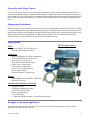
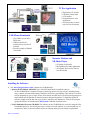
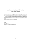
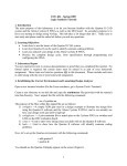
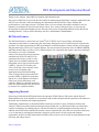
DE2 Development and Education Board
Thank you for using the Altera DE2 Development and Education board.
The purpose of this board is to provide the ideal vehicle for learning about digital logic, computer organization, and
FPGAs. It uses the state-of-the-art technology in both hardware and CAD tools to expose students and
professionals to a wide range of topics. The board offers a rich set of features that make it suitable for use in a
laboratory environment for university and college courses, for a variety of design projects, as well as for the
development of sophisticated digital systems. Altera provides a suite of supporting materials for the DE2 board,
including tutorials, “ready-to-teach” laboratory exercises, and illustrative demonstrations.
DE2 Board Features
The DE2 board features a state-of-the-art Cyclone® II 2C35 FPGA in a 672-pin package. All important
components on the board are connected to pins of this chip, allowing the user to control all aspects of the board’s
operation. For simple experiments, the DE2 board includes a sufficient number of robust switches (of both toggle
and push-button type), LEDs, and 7-segment displays. For more advanced experiments, there are SRAM, SDRAM,
and Flash memory chips, as well as a 16 x 2 character display. For experiments that require a processor and simple
I/O interfaces, it is easy to instantiate
Altera’s Nios II processor and use interface
standards such as RS-232 and PS/2. For
experiments that involve sound or video
signals, there are standard connectors for
microphone, line-in, line-out (24-bit audio
CODEC), video-in (TV Decoder), and
VGA (10-bit DAC); these features can be
used to create CD-quality audio
applications and professional-looking
video. For larger design projects the DE2
provides USB 2.0 connectivity (both host
and device), 10/100 Ethernet, an infrared
(IrDA) port, and an SD memory card
connector. Finally, it is possible to connect
other user defined boards to the DE2 board
by means of two expansion headers.
Supporting Material
Software provided with the DE2 board features the Quartus® II Web Edition CAD system, and the Nios® II
Embedded Processor. Also included are several aids to help students and professionals experiment with features of
the board, such as tutorials and example applications.
Traditionally, manufacturers of educational FPGA boards have provided a variety of hardware features and
software CAD tools needed to implement designs on these boards, but very little material has been offered that
could be used directly for teaching purposes. Altera's DE2 board is a significant departure from this trend. In
addition to the DE2 board's hardware and software, Altera Corporation provides a full set of associated laboratory
exercises that can be performed in a laboratory setting for typical courses on logic design and computer
organization. In effect, the DE2 board and the available exercises can be used as a ready-to-teach platform for both
university and college courses.
Altera Corporation
1
University and College Courses
Courses on the design of logic circuits and computer organization usually include a laboratory component. In a
modern curriculum the laboratory equipment should ideally exemplify state-of-the-art technology and design tools,
but be suitable for exercises that range from simple tasks illustrating fundamental concepts to challenging designs
that require knowledge of advanced topics. The DE2 board is designed to be the ideal equipment in all of these
cases.
Engineering Professionals
With its advanced Cyclone® II FPGA, flexible memory options, and a plethora of advanced I/O devices, the DE2
board is an ideal platform for the implementation of many types of digital systems. Engineering professionals will
appreciate the wealth of design examples provided with the board, and will enjoy experimenting with audio, video,
USB, network, and memory applications. The DE2 board is an ideal vehicle for implementing embedded
applications such as those that feature the Altera Nios II embedded processor.
Specifications
FPGA
DE2 Package Contents
• Cyclone II EP2C35F672C6 FPGA and
EPCS16 serial configuration device
I/O Devices
•
•
•
•
•
•
•
Built-in USB Blaster for FPGA configuration
10/100 Ethernet, RS-232, Infrared port
Video Out (VGA 10-bit DAC)
Video In (NTSC/PAL/Multi-format)
USB 2.0 (type A and type B)
PS/2 mouse or keyboard port
Line-in, Line-out, microphone-in
(24-bit audio CODEC)
• Expansion headers (76 signal pins)
Memory
• 8-MB SDRAM, 512-KB SRAM, 4-MB Flash
• SD memory card slot
Switches, LEDs, Displays, and Clocks
•
•
•
•
•
•
18 toggle switches
4 debounced pushbutton switches
18 red LEDs, 9 green LEDs
Eight 7-segment displays
16 x 2 LCD display
27-MHz and 50-MHz oscillators, external SMA clock input
Examples of Advanced Applications
The DE2 board can be used to implement a wide assortment of interesting design projects. Some example
applications are shown on the next page.
Altera Corporation
2
TV Box Application
•
•
•
•
High quality TV decoder
CD quality 24-bit audio
VGA monitor
Ideal platform for video
applications
• All software driver source
code for Nios II included
USB Mouse Paintbrush
• Uses USB 2.0 ports on the
DE2 board
• USB host and device
software drivers for Nios II
included
• Provides example of SRAM
video buffer
Karaoke Machine and
SD Music Player
• CD quality 24-bit audio
• Ideal platform for audio applications
• All software driver source code for
Nios II included
Installing the Software:
1. The Altera Design Software Suite contains two CD-ROM disks:
• Quartus II Web Edition CD-ROM: Users of the DE2 board need to install the software
on this CD-ROM disk. It supports all stages of the design process for logic circuits, including design
entry, synthesis, placement and routing, simulation, and device programming. This software is an ideal
tool for designing any type of logic circuits, from simple ones that may be used for learning purposes to
multi-million gate designs that are found in modern commercial products. To install the Quartus II
software, simply insert the disk into your CD drive and follow the instructions. Tutorials for using the
Quartus II software are included in the DE2 System CD-ROM, described below.
• Nios II Embedded Processor CD-ROM: The software on this CD-ROM disk is needed for using the Nios
II embedded processor. The Nios II processor is widely used in the industry as a powerful and easy-touse processor, but it is also an excellent vehicle for learning about topics in computer organization.
Altera Corporation
3
2. Install the USB Blaster driver software, as explained in the tutorial Getting Started with Altera’s DE2 Board.
3. The DE2 System CD-ROM provides a variety of material for use with the board. To examine the disk, insert it
into your computer’s CD drive and use a utility like Windows Explorer to peruse the disk’s contents:
• DE2 User Manual and Data Sheets: the complete manual for using the DE2 board is provided in the
DE2_user_manual folder on the CD-ROM. Data Sheets for each of the I/O devices on the DE2 board,
such as the memory chips, LCD, Audio CODEC, IrDA, RS232, TV Decoder, USB, Ethernet, and VGA
DAC are provided in the Datasheets folder.
• DE2 Schematic Diagrams: detailed schematic diagrams for all circuits on the DE2 board are provided in the
folder called DE2_schematics.
• Tutorials: a set of tutorials are included in the DE2_tutorials folder on the CD-ROM that illustrate how to
use the Quartus II software and the DE2 board. Topics covered in the tutorials include Quartus II
Introduction, Getting Started with Altera’s DE2 Board, Using the Library of Parameterized Modules
(LPMs), Timing Considerations, Quartus II Simulation, and (coming soon) Using Nios II and SOPC
Builder with the Quartus II Software.
• Laboratory Exercises: a set of ready-to-teach laboratory exercises are included on the CD-ROM. These
exercises can be used for self-study, or they can serve as a significant part of the laboratory component of
a university or college course in digital logic. The early exercises are simple ones that illustrate
fundamental concepts and perform simple operations on the DE2 board, like using switches and
controlling LEDs and 7-segment displays. Later exercises progress to more advanced topics such as
arithmetic circuits, counters, state machines, memory devices, datapaths, and simple processors. The
tutorials are found in the folder DE2_lab_exercises on the CD-ROM, with subfolders provided for
versions of the exercises that use VHDL and Verilog hardware description languages.
• Demonstrations: a set of demonstrations that illustrate the DE2 board’s features are provided in the
DE2_demonstrations folder. Examples include: VGA Graphics Generator, TV (NTSC/PAL) Controller,
Music Player, SD Card Sound Player, PS/2 Keyboard, SDRAM Controller, Flash Controller, RS-232
Controller, USB Controller, and Ethernet Controller. A programming file that can be downloaded into
the DE2 board is provided for each demonstration example, as well as the source code in Verilog HDL.
• DE2 Control Panel: This application, which runs on PC platforms under Windows XP, allows remote
control of the DE2 board through a USB cable. The DE2 Control Panel is found in the folder called
DE2_control_panel; instructions for its use are given in the DE2 User Manual.
Power on Test
To design and implement circuits on the DE2 board, it is necessary to install the accompanying software, as
described on the previous page. Without installing any software, a simple power on test can be done:
1. Plug the supplied 9 volt DC power supply into an AC power outlet (100V - 240V), and then connect this power
supply to the DE2 board. Make sure the RUN/PROG switch is in the RUN position
2. Connect the DE2 board to your computer using the supplied USB cable
3. Optionally connect the DE2 board VGA connector to a VGA monitor, and the line-out (green) audio connector
to a speaker or headset
4. Turn on the DE2 power by pressing the red power button. You should be able to observe the following:
•
•
•
•
•
The blue POWER LED is on and the blue GOOD LED (Cyclone II FPGA configured) is on
The 7-segment displays show a sequence of characters
The red and green LEDs are flashing
The VGA monitor is displaying a color pattern
A humming sound is produced by the audio line-out if switch SW17 is UP.
Change SW17 to be DOWN and use microphone-in or line-in to hear sound
• The LCD display shows Welcome to the Altera DE2 Board
Altera Corporation
4