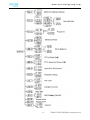
1
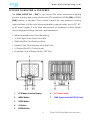
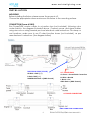
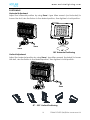
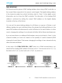
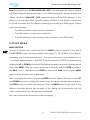
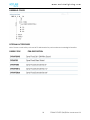
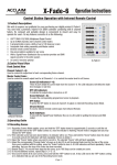
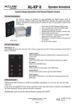
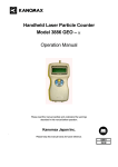
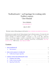
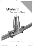
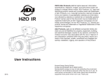
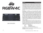
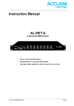
QA / QW™
A CC L A IM L I GH T IN G | DYNA FLOOD QA / QW™ | user manual 2.0
DYNA FLOOD
user manual 2.0 w w w . a c c l a i m l i g h t i n g . c o m ©2014 ACCLAIM LIGHTING all rights reserved. Information, specifications, diagrams, images,
and instructions herein are subject to change without notice. ACCLAIM LIGHTING logo
and identifying product names and numbers herein are trademarks of ACCLAIM LIGHTING.
Copyright protection claimed includes all forms and matters of copyrightable materials and
information now allowed by statutory or judicial law or hereinafter granted. Product
names used in this document may be trademarks or registered trademarks of their
respective companies and are hereby acknowledged. All non-ACCLAIM brands and
product names are trademarks or registered trademarks of their respective companies.
ACCLAIM LIGHTING and all affiliated companies hereby disclaim any and all liabilities for
property, equipment, building, and electrical damages, injuries to any persons, and direct
or indirect economic loss associated with the use or reliance of any information contained
within this document, and/or as a result of the improper, unsafe, insufficient and negligent
assembly, installation, rigging, and operation of this product.
ACCLAIM LIGHTING USA | 6122 S. Eastern Ave. | Los Angeles, CA. 90040
323-213-4626 | 323-582-3108 fax | www.acclaimlighting.com | [email protected]
ACCLAIM LIGHTING B.V. | Junostraat 2 | 6468 EW Kerkrade, Netherlands
+31 45 546 85 60 | +31 45 546 85 97 fax | www.acclaimlighting.eu | [email protected]
2 DYNA FLOOD QA/QW™ User Manual 2.0
w w w . a c c l a i m l i g h t i n g . c o m CONTENTS
General Information
4
Limited Warranty
6
Safety Instructions
7
Fixture Overview & Features
8
Installation
9
Understanding DMX
11
Fixture Menu
13
Fixture Control & DMX Channels
18
Troubleshooting
19
Cleaning and Maintenance
20
Technical Specifications
21
Ordering Codes & Optional Accessories
22
M A N U A L
U P D A T E S
Please check www.acclaimlighting.com for the latest version of this manual.
3 DYNA FLOOD QA/QW™ User Manual 2.0
w w w . a c c l a i m l i g h t i n g . c o m GENERAL INFORMATION
INTRODUCTION
Congratulations, you have just purchased one of the most innovative and reliable
lighting fixtures on the market today! The DYNA FLOOD QA / QW™ has been designed to
perform reliably for years when the guidelines in this booklet are followed. Please read
and understand the instructions in this guide carefully and thoroughly before attempting
to install and operate this product. These instructions contain important information
regarding safety during use and maintenance.
IP66 RATED
An IP rated lighting fixture is one, which is commonly installed in outdoor environments
and has been designed with an enclosure that effectively protects the ingress (entry) of
external foreign objects such as dust and water. The International Protection (IP) rating
system is commonly expressed as "IP" (Ingress Protection) followed by two numbers (i.e.
IP66) where the numbers define the degree of protection. The first digit (Foreign Bodies
Protection) indicates the extent of protection against particles entering the fixture and
the second digit (Water Protection) indicates the extent of protection against water
entering the fixture. An IP66 rated lighting fixture such as the DYNA FLOOD QA / QW™ is
one, which has been designed and tested to protect against the ingress of dust (6) and
high-pressure water jets from any direction (6).
UNPACKING
Thank you for purchasing the DYNA FLOOD QA / QW™ by ACCLAIM LIGHTING®. Every
unit has been thoroughly tested and has been shipped in perfect operating condition.
Carefully check the shipping carton for damage that may have occurred during
shipping. If the carton appears to be damaged, carefully inspect your unit for damage
and be sure all accessories necessary to operate the unit have arrived intact. In the
event damage has been found or parts are missing, please contact our customer
support team for further instructions. Please do not return this unit to your dealer without
first contacting customer support at the number listed below. Please do not discard the
shipping carton in the trash. Please recycle whenever possible.
4 DYNA FLOOD QA/QW™ User Manual 2.0
w w w . a c c l a i m l i g h t i n g . c o m CUSTOMER SUPPORT
ACCLAIM LIGHTING® provides a customer support line, to provide set up help and to
answer any question should you encounter problems during your set up or initial
operation. You may also visit us on the web at www.acclaimlighting.com for any
comments or suggestions. For service related issue please contact ACCLAIM LIGHTING®.
Service Hours are Monday through Friday 8:00 a.m. to 4:30 p.m. PST.
Voice: 323-213-4594
Fax: 323-832-9142
E-mail: [email protected]
PRODUCT RETURNS
All returned service items whether under warranty or not, must be freight pre-paid and
accompany a return authorization (R.A.) number. The R.A. number must be clearly
written on the outside of the return package. A brief description of the problem as well
as the R.A. number must also be written down on a piece of paper and included in the
shipping container. Please use the original packaging and materials to transport the
fixture in for repair service. If the unit is under warranty, you must provide a copy of your
proof of purchase invoice. Items returned without a R.A. number clearly marked on the
outside of the package will be refused and returned at customer’s expense. You may
obtain a R.A. number by contacting customer support at 323-213-4694.
I M P O R T A N T
N O T I C E !
There are no user serviceable parts inside this unit. Do not attempt any repairs yourself;
doing so will void your manufactures warranty. Damages resulting from modifications to
this fixture and/or the disregard of safety and general user instructions found in this user
manual void the manufactures warranty and are not subject to any warranty claims
Specifications and improvements in the design of these products and this manual are subject to
change without any prior written notice.
5 DYNA FLOOD QA/QW™ User Manual 2.0
w w w . a c c l a i m l i g h t i n g . c o m LIMITED WARRANTY
A. Acclaim Lighting™ hereby warrants, to the original purchaser, Acclaim Lighting™ finished products to be free
of manufacturing defects in material and workmanship for a standard period of:
Fixtures: 5 Years (1,825 days) from the date of purchase, beginning on 01/01/2013.
Flex Products: 3 Years (1,095 days) from the date of purchase, beginning on 01/01/2013.
DMX Controllers, Power Supplies, Drivers: 2 Years (730 days) from the date of purchase, beginning on 01/01/2013.
This warranty shall be valid only if the product is purchased within the United States of America, including
possessions and territories, Mexico and Canada and pre-approved in written form by Acclaim Lighting. It is the
owner’s responsibility to establish the date and place of purchase and warranty terms by acceptable evidence,
at the time service is sought.
B. For warranty service, send the product only to the Acclaim factory. All shipping charges must be pre-paid. If
the requested repairs or service (including parts replacement) are within the terms of this warranty, Acclaim
Lighting™ will pay return shipping charges only to a designated point within the United States. If the entire
instrument is sent, it must be shipped in its original package. No accessories should be shipped with the product.
If any accessories are shipped with the product, Acclaim Lighting™ shall have no liability whatsoever for loss of
or damage to any such accessories, nor for the safe return there of. Acclaim reserves the right to replace the
item with same or similar product at its discretion.
C. This warranty is void if the serial number has been altered or removed; if the product is modified in any manner
which Acclaim concludes, after inspection, affects the reliability of the product; if the product has been
repaired or serviced by anyone other than the Acclaim Lighting™ factory unless prior written authorization was
issued to purchaser by Acclaim Lighting™; if the product is damaged because not properly maintained as set
forth in the instruction manual.
D. This is not a service contract, and this warranty does not include maintenance, cleaning or periodic check-up
nor do we guarantee as part of this warranty any lumen performance during period. Parts not covered by this
warranty include: fuses, external power supplies, third party items not manufactures by Acclaim lighting. During
the period specified above, Acclaim Lighting™ will replace defective parts at its expense, and will absorb all
expenses for warranty service and repair labor by reason of defects in material or workmanship. The sole
responsibility of Acclaim Lighting™ under this warranty shall be limited to the repair of the product, or
replacement thereof, including parts, at the sole discretion of Acclaim Lighting™. At no time will installation or
re-installation or products labor or liability costs will be assumed by Acclaim Lighting. All products covered by
this warranty were manufactured after January 1, 2012, and bear identifying serial number marks to that effect
E. Acclaim Lighting™ reserves the right to make changes in design and/or improvements upon its products
without any obligation to include these changes in any products theretofore manufactured No warranty,
whether expressed or implied, is given or made with respect to any accessory supplied with products describe
above. Except to the extent prohibited by applicable law, all implied warranties made by Acclaim Lighting™ in
connection with this product, including warranties of merchantability or fitness, are limited in duration to the
warranty period set forth above. And no warranties, whether expressed or implied, including warranties of
merchantability or fitness, shall apply to this product after said period has expired.
F. Marine or extreme weather location applications using Acclaim lighting products are subject to a 2 year
limited warranty and Acclaim must be notified prior to delivery of units for such applications so that preventative
treatment can be made to the products to ensure proper performance and product life with a special marine
code coating / sealing process at an additional cost.
G. The consumer’s and or Dealer’s sole remedy shall be such repair or replacement as is expressly provide above;
and under no circumstances shall Acclaim Lighting™ be liable for any loss or damage, direct or consequential,
arising out of the use of, or inability to use, this product. This warranty is the only written warranty applicable to
Acclaim Lighting™ Products and supersedes all prior warranties and written descriptions of warranty terms and
conditions heretofore published.
6 DYNA FLOOD QA/QW™ User Manual 2.0
w w w . a c c l a i m l i g h t i n g . c o m SAFETY INSTRUCTIONS
•
DYNA FLOOD QA / QW™ fixtures are an extremely sophisticated piece of
electronic equipment. To guarantee a smooth operation, it is important
to follow the guidelines in this manual. The manufacturer of this device
will not accept responsibility for damages resulting from the misuse of this
fixture due to the disregard of the information printed in this manual.
•
For proper operation, follow the Installation guidelines described on
page 9 of this manual. Only qualified and/or certified personal should
preform installation of this fixture and only the original mounting
hardware (brackets, holders, clamps, screws, covers, safety cables)
included with this fixture should be used for installation.
•
This device falls under PROTECTION CLASS 2.
•
Verify supply voltage is according per product documentation/labels.
•
NEVER install or service with main power connected, disconnect before
doing so to avoid risk of electric hazard or shock.
•
DO NOT operate fixture if the power cord, housing, lenses, or filter is visibly
damaged.
•
CAUTION surface temperature may reach up to 65°C/149°F when in use.
•
AVOID direct exposure to light source of this fixture to prevent risk of injury
to your retina, which may induce blindness, especially those suffering
from EPILEPSY.
•
KEEP any combustible materials away from this fixture at all times.
7 DYNA FLOOD QA/QW™ User Manual 2.0
w w w . a c c l a i m l i g h t i n g . c o m FIXTURE OVERVIEW & FEATURES
The DYNA FLOOD QA / QW™ is our newest IP66 rated architectural lighting
product featuring high-power Quad color LEDs available in RGBA (QA) or RGBW
(QW) versions, a standard Grey colored finished die cast aluminum housing
(optional Black & White color finishes available by special order), and in 20°, 40°,
or 60° beam angles. It is an ideal replacement for traditional outdoor fixtures
used to highlight buildings, facades, and landscapes.
• Brilliant Illumination and Color Rendering
• 10 x 5W High-Power Quad Color LEDs
• IP66 Rated Die Cast Aluminum Body
• Flexible X and Y Rotating Axis Mounting Points
• 4 Channel DMX 512 Control Mode
• Reversible Control Display Option (180° Flip)
1.
LCD Menu Function Display
6.
AC/Power Leads
2.
MENU Button
7.
DMX Signal Leads IN/OUT (2 Pairs)
3.
ENTER Button
4.
UP Button
5.
DOWN Button
8 DYNA FLOOD QA/QW™ User Manual 2.0
w w w . a c c l a i m l i g h t i n g . c o m INSTALLATION
MOUNTING
Before installing the fixture, please ensure the power is off.
Choose the appropriate screws and secure the fixture to the mounting surface.
CONNECTION (Power & DMX)
Run Power/DMX combo cables to a junction box (not included), following color
codes listed in the diagram illustrated above. Connect power and signal cables
using wire nuts or wiring terminal per local electrical code instructions. For damp or
wet locations, make sure to use IP rated junction boxes (not included), as per
manufacturer’s instructions. (See diagram below)
DMX SIGNAL LEADS (2 PAIRS)
W: White = DMX (-/+)
AC / POWER LEADS
G: Green = Ground Earth Connection
R: Red = DMX (-/+)
SHARED GND: Black = (DMX Ground)
N: White = Neutral
L: Black = Live
GND: Black = (DMX Ground)
AC POWER CONNECTONS
DMX SIGNAL LINE CONNECTIONS
9 DYNA FLOOD QA/QW™ User Manual 2.0
w w w . a c c l a i m l i g h t i n g . c o m POSITIONING
Horizontal Adjustment
Adjust the horizontal position by using 2mm L type Allen wrench (not included) to
loosen Hex bolt, aim the fixture to the desired position, then tighten to hold position.
2mm
2mm
180° Horizontal Positioning
Vertical Adjustment
Adjust the horizontal position by using 5mm L type Allen wrench (included) to loosen
Hex bolt, aim the fixture to the desired position, then tighten to hold position.
5mm
47° - 223° Vertical Positioning
10 DYNA FLOOD QA/QW™ User Manual 2.0
w w w . a c c l a i m l i g h t i n g . c o m UNDERSTANDING DMX
DMX-512
DMX is short for Digital Multiplex. This is a universal protocol used by most lighting and
controller manufactures as a form of communication between various intelligent
fixtures and controllers. A DMX controller sends the DMX data instructions to the
fixture allowing the user to control the different aspects of an intelligent light. DMX
data is sent out as serial data that travels from fixture to fixture via data “IN” and
data “OUT” cables located on the fixtures.
DMX LINKING
To ensure proper DMX data transmission, always use proper DMX cables and a
terminator. When using several DMX fixtures try to use the shortest cable path
possible. Never split a DMX line with a “Y” style connector. The order in which the
fixtures are connected in a DMX line does not influence the DMX addressing. For
example; a fixture assigned a starting DMX address of 1 may be placed anywhere in
the DMX chain, at the beginning, at the end, or anywhere in the middle. The DMX
controller knows to send data assigned to address 1 to that fixture no matter where it
is located in the DMX chain. The DYNA FLOOD QA / QW™ can be controlled via
DMX-512 protocol and the DMX address is set via the control menu.
DMX CABLE (Data Cable) REQUIREMENTS
Accu Cable or Belden 9842 cable brands are recommended. (Two conductor,
shielded digital DMX cable rated at 120 ohms) Also, remember a DMX line must be
daisy chained and cannot be split, unless using an approved DMX splitter such as
ACCALIM’s DD-6 WM PRO™.
DMX TERMINATOR
It is recommended to add a DMX terminator to the last unit in the DMX daisy chain.
This can be done by soldering a 120-ohm ¼ Watt resistor between DMX (-) and DMX
(+) of the DMX OUTPUT cable from the last unit in the daisy chain.
11 DYNA FLOOD QA/QW™ User Manual 2.0
w w w . a c c l a i m l i g h t i n g . c o m DMX ADDRESSING
All fixtures should be given a DMX starting address when using a DMX controller, so
the correct fixture responds to the correct control signal. This digital starting address
is the channel number from which the fixture starts to “listen” to the digital control
information sent out from the DMX controller. The allocation of this starting DMX
address is achieved by setting the correct DMX address on the digital display
located on the top of the fixture.
You can set the same starting address for all fixtures or a group of fixtures, or set
different address for each individual fixture. Be advised that setting all fixtures to the
same DMX address will subsequently control all fixtures in the same fashion, in other
words, changing the settings of one channel will affect all the fixtures simultaneously.
If you set each fixture to a different DMX address, each unit will start to “listen” to the
channel number you have set, based on the quantity of control channels (DMX
channels) of each fixture. That means changing the settings of one channel will only
affect the selected fixture.
In the case of the DYNA FLOOD QA / QW™ which is a 4 DMX channel fixture, you
should set the starting DMX address of the first unit to 1, the second unit to 5 (1 + 4),
the third unit to 9 (5 + 4), the fourth unit to 13 (9 + 4) and so on.
Address 9
Address 5
Address 1
DMX
CONTROLLER
12 DYNA FLOOD QA/QW™ User Manual 2.0
w w w . a c c l a i m l i g h t i n g . c o m Note: During start-up the DYNA FLOOD QA / QW™ will automatically detect whether
a DMX data signal is being received or not. If DMX data signal is being received, the
display will show "Addr=XXX" (XXX representing the actual DMX address). If the
fixture is not receiving a DMX signal the display will flash. If your fixture is connected
to a DMX controller and the display is flashing (not receiving a DMX signal), please
check the following:
-
The DMX controller is switched off or defective.
-
The DMX cable or connection is defective.
-
A DMX termination is connected to the last fixture in your DMX chain.
FIXTURE MENU
MAIN FUNCTION
To enter the fixture menu, press and hold the MENU button for approx. 8 seconds. If
the KEY LOCK feature has been enabled (see page 17), “0” will flash on the display,
prompting you to enter the password.
The password can be any combination of
1-4 numeric digits between 1 and 9999. Enter the password (0-9999) by pressing and
holding the UP or DOWN buttons until the desired numeric password is displayed and
then press ENTER. After the correct password is selected and the ENTER is pressed,
the Addr menu is displayed. Press ENTER to access the Addr menu or press MENU
again until the desired menu is displayed.
Select the desired function by pressing ENTER and the display will flash. Use the UP
and DOWN buttons to change the mode. Once the desired mode is selected, press
the ENTER button to confirm the selection. Press the MENU button to go back to the
previous functions without any change, or the display will automatically exit the
menu mode without any change after 60 seconds.
The main functions are illustrated on the next page:
13 DYNA FLOOD QA/QW™ User Manual 2.0
w w w . a c c l a i m l i g h t i n g . c o m 14 DYNA FLOOD QA/QW™ User Manual 2.0
w w w . a c c l a i m l i g h t i n g . c o m DMX 512 ADDRESS SETTING
Press MENU until
is shown on the display and press ENTER and the display will
flash. Press DOWN and UP to select the desired DMX address (1-512). Once the
desired DMX address has been selected, press ENTER to confirm the selection. Press
MENU to go back to the previous functions without any change, or the display will
automatically exit the menu mode without any change after 60 seconds.
MANUAL COLOR
Press MENU until
is shown on the display and press ENTER and the display will
flash. Press DOWN and UP to select the desired mode
thru
or
.
Once
has been selected, press DOWN and UP to select the
(Red
Color),
(Green Color),
(Blue Color), or
(White/Amber Color)
mode. Once has desired mode has been selected, press ENTER to setup then use
DOWN and UP to adjust the value (000-255) and press ENTER to confirm selection.
Press MENU to go back to the previous functions without any change, or the display
will automatically exit the menu mode without any change after 60 seconds
PROGRAMS
Press MENU until
is shown on the display and press ENTER and the display
will flash. Press DOWN and UP to select the desired program
thru
.
Once selected, press ENTER to setup, then use DOWN and UP to select the desired
fade time
thru
and press ENTER to confirm. Press MENU to go back to
the previous functions without any change, or the display will automatically exit the
menu mode without any change after 60 seconds
BLACKOUT MODE
Press MENU until
is shown on the display and press ENTER and the display will
flash. Press DOWN and UP to select
(Master/Slave),
(Blackout), or
(Last State) mode. Once the desired mode has been selected, press ENTER to
confirm the selection. Once
has been selected, the fixture will restore the last
state when the DMX signal is lost or disconnected. For example, if the DMX signal is
the color red when the DMX signal is lost or disconnected, the color red will be kept
when the DMX signal is restored. Press MENU to go back to the previous functions
without any change, or the display will automatically exit the menu mode without
any change after 60 seconds.
15 DYNA FLOOD QA/QW™ User Manual 2.0
w w w . a c c l a i m l i g h t i n g . c o m WHITE BALANCE
Press MENU until
is shown on the display and press ENTER and the display
will flash. Press DOWN and UP to select
(Red),
(Green), or
(Blue) mode. Once the desired mode has been selected, press ENTER to confirm
selection, then press DOWN and UP to adjust the value (125 - 255) and press ENTER to
store value. Press MENU to go back to the previous functions without any change, or
the display will automatically exit the menu mode without any change after 60
seconds.
PTCL (Photo Cell)
Press MENU until
is shown on the display and press ENTER and the display
will flash. Press DOWN and UP to select
(controlled by sunlight) or
(not controlled by sunlight). Once the desired mode has been selected, press ENTER
to confirm selection. Press MENU to go back to the previous functions without any
change, or the display will automatically exit the menu mode without any change
after 60 seconds.
PTCL INTENSITY (Photo Cell)
Press MENU until
is shown on the display and press ENTER and the display
will flash. Press DOWN and UP to select intensity value
to
. Once the
desired value has been selected, press the ENTER button to confirm selection. Press
MENU to go back to the previous functions without any change, or the display will
automatically exit the menu mode without any change after 60 seconds.
AUTO SHUT-OFF (Hours)
Press MENU until
is shown on the display and press ENTER and the display will
flash. Press DOWN and UP to change the time
thru
(hours). Once the
desired time has been selected, press ENTER to confirm selection. Press MENU to go
back to the previous functions without any change, or the display will automatically
exit the menu mode without any change after 60 seconds.
PASSWORD SETUP
Press MENU until
is shown on the display and press ENTER and the display will
flash. Press DOWN and UP to select a password
thru
. Once the
desired password has been selected, press ENTER to confirm selection. Press MENU to
go back to the previous functions without any change, or the display will
automatically exit the menu mode without any change after 60 seconds.
16 DYNA FLOOD QA/QW™ User Manual 2.0
w w w . a c c l a i m l i g h t i n g . c o m KEY LOCK
Press MENU until
is shown on the display and press ENTER and the display will
flash. Press DOWN and UP to select
(locks the keyboard) or
(normal).
Once the desired mode has been selected, press ENTER to confirm selection. Press
MENU to go back to the previous functions without any change, or the display will
automatically exit the menu mode without any change after 60 seconds.
DISPLAY INVERSION
Press MENU until
is shown on the display and press ENTER to change the
display mode between
(display normal), or press ENTER again to change the
display mode to
(display inversion). Press MENU to go back to the previous
functions without any change, or the display will automatically exit the menu mode
without any change after 60 seconds.
AUTO TEST
Press MENU until
is flashing on the display and press ENTER to start built-in
self-test. Press MENU to go back to the previous functions without any change, or the
display will automatically exit the menu mode without any change after 60 seconds.
LED DISPLAY (On/Off)
Press MENU until
is shown on the display and press ENTER and the display will
flash. Press DOWN and UP to select
(display on) or
(display off 60
seconds after exit menu) mode and press ENTER. Press MENU to go back to the
previous functions without any change, or the display will automatically exit the
menu mode without any change after 60 seconds.
TEMPERATURE
Press MENU until
is shown on the display and press ENTER and the display will
show the temperature of the fixture. Press MENU to go back to the previous functions
without any change, or the display will automatically exit the menu mode without
any change after 60 seconds.
FIXTURE TIME
Press MENU until
is shown on the display and press ENTER and the display
will show the number of working hours of the fixture. Press MENU to go back to the
previous functions without any change, or the display will automatically exit the
menu mode without any change after 60 seconds.
17 DYNA FLOOD QA/QW™ User Manual 2.0
w w w . a c c l a i m l i g h t i n g . c o m VERSION
Press MENU until
is shown on the display and press ENTER and the display
will blink. Press DOWN and UP to display
(application program version) or
(underlying version which is used to upgrade the application program). Press
MENU to go back to the previous functions without any change, or the display will
automatically exit the menu mode without any change after 60 seconds.
FIXTURE CONTROL & DMX CHANNELS
The DYNA FLOOD QUAD QA / QW™ can be controlled by a universal DMX Controller
or by a VD-T (both sold separately). No need to turn the fixture off when you change
the DMX address, as the new DMX address will be stored immediately. Each time
you power the fixture ON, it will show
on the display, then the fixture will be
ready to receive a DMX signal or run any of the built-in programs.
DMX CONTROLLER
A DMX address from 1 to 512 must be set for each fixture in use in order to receive a
DMX signal from a universal controller. Press MENU until
is shown on the
display and press ENTER and the display will flash. Press DOWN and UP to change the
DMX address. Once the desired DMX address has been selected, press ENTER to
confirm the selection. Press MENU to go back to the previous functions without any
change, or the display will automatically exit the menu mode without any change
after 60 seconds. Please refer to the diagram below to address the first 4 units:
Address 9
Address 5
Address 1
DMX
CONTROLLER
VD-T
VD-T is a specially designed setup tool, which can be used to control a compatible
fixture. By connecting VD-T to any fixture via an XLR cable, you can easily setup or
change the DMX Address, Channel Mode, White Balance, Manual Color, and
Fade/Speed functions. If you use VD-T to control the fixture, you can follow the VD-T
User Manual. Once you set the DMX address using the VD-T, you can then control
the fixture(s) by a universal DMX controller.
18 DYNA FLOOD QA/QW™ User Manual 2.0
w w w . a c c l a i m l i g h t i n g . c o m DMX CHANNELS
Channel
1
2
3
Value
000-255
000-255
000-255
Function
RED
GREEN
BLUE
4
000-255
WHITE
TROUBLE SHOOTING
PROBLEM
POSSIBLE CAUSE
ACTION
The unit does not work,
no light.
Incorrect power cable
connection.
Check the connection of
power.
Incorrect mains voltage.
Measure the mains voltage
on the main connector.
Check DMX connectors and
cables to see if link properly.
The unit does not respond
properly to the DMX control.
Incorrect DMX cable
connection.
Repair or replace damaged
wires.
Incorrect address
assignment to the units.
Unfinished data connection.
It has been set up an
operating mode different
from the DMX mode used.
Check the addresses of the
units and the protocol
settings.
Insert a terminal plug in the
output jack of the last unit of
the connection.
Check the operating mode
set up.
Try to use another DMX
controller.
19 DYNA FLOOD QA/QW™ User Manual 2.0
w w w . a c c l a i m l i g h t i n g . c o m CLEANING AND MAINTENANCE
CLEANING
Frequent cleaning is recommended to insure proper function and extended life.
•
Clean LED lens surface with a soft cloth using normal glass cleaning liquid.
•
Always dry lens carefully.
•
Clean surface at least every 30 days to avoid dust accumulation.
MAINTENANCE
Regular inspections are recommended to insure proper function and extended life.
There are no user serviceable parts inside this fixture, please refer all other service
issues to an authorized ACCLAIM service technician. Should you need any spare
parts, please order genuine parts from your local ACCLAIM dealer.
Please refer to the following points during routine inspections:
•
A detailed electric check by an approved electrical engineer every 3 months, to
make sure the circuit contacts are in good condition and prevent overheating.
•
Be sure all screws and fasteners are securely tightened at all times.
•
Check for any deformations on the housing, color lenses, installation hardware
and points. Deformations in the housing could allow for dust to enter into the
fixture. Damaged installation hardware or unsecured fixtures could cause a
hazard and/or injury to a person(s).
•
Electric power supply cables must not show any damage, material fatigue or
sediments.
20 DYNA FLOOD QA/QW™ User Manual 2.0
w w w . a c c l a i m l i g h t i n g . c o m TECHNICAL SPECIFICATIONS
Please Note: Specifications are subject to change without any prior written notice.
DIMENSIONAL DRAWINGS
21 DYNA FLOOD QA/QW™ User Manual 2.0
w w w . a c c l a i m l i g h t i n g . c o m ORDERING CODES
OPTIONAL ACCESSORIES
Note: Please consult with your local ACCLAIM dealer for part number and ordering information.
ORDER CODE
ITEM DESCRIPTION
22 DYNA FLOOD QA/QW™ User Manual 2.0