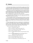
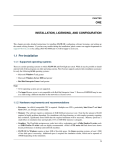
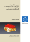
1
PMIC MODEL MI-900 Data Analysis Guide PRECISION MEASUREMENTS AND INSTRUMENTS CORPORATION 3665 SW Deschutes Street Corvallis, OR 97333 TEL: 541-753-0607 FAX: 541-753-0610 EMAIL: [email protected] © Precision Measurements and Instruments Corporation September 6, 2007 M I - 9 0 0 D A T A A N A L Y S I S G U I D E PMI-900-730 MI-900 Documentation The following documentation 1 is provided for this product: PMIC Model MI-900 Installation and Operator Guide (PMI-900-710) PMIC Model MI-900 Troubleshooting Guide (PMI-900-720) PMIC Model MI-900 CTE Analysis and Troubleshooting Guide (PMI-900-730) PMIC Model MI-900 Limited Warranty and System Components (PMI-900-740) 1 The documentation for MI-900 is available on CD (PMI-900-700). Page i ©PMIC September 6, 2007 M I - 9 0 0 D A T A A N A L Y S I S G U I D E PMI-900-730 TABLE OF CONTENTS MI-900 Documentation i TABLE OF CONTENTS ii FIGURES Chapter 1. iii Introduction 4 MI-900 4 The MI-900 Data Analysis Application 4 Prerequisites 4 About this Guide 4 Chapter 2. Installation 5 Chapter 3. CTE Data Analysis 7 Running the Program 7 Extracting Data for a Particular Range 20 Extracting Data for a Specified Temperature Interval 22 Chapter 4. 26 Preparing Reports Calculating Average CTE 30 Closing the Program 31 Chapter 5. 33 Error Calculation Appendix A. Troubleshooting 35 Appendix B. Some Data Selection Examples 36 1. Raw data file size ≤ 64,000 data lines. 36 2. Raw data file size › 64,000 data lines. 36 Index 37 Page ii ©PMIC September 6, 2007 M I - 9 0 0 D A T A A N A L Y S I S G U I D E PMI-900-730 FIGURES Figure 1. Figure 2. Figure 3. Figure 4. Figure 5. Figure 6. Figure 7. Figure 8. Figure 9. Figure 10. Figure 11. Figure 12. Figure 13. Figure 14. Figure 15. Figure 16. PKCHECK: Sheet 1. Raw and Selected Data. .............................................................................................................................................12 PKCHECK: Ellipse.........................................................................................................................................................................................13 PKCHECK: Chart 1 (1-16000).......................................................................................................................................................................14 CTE Forms - Make Graphs – part 1..............................................................................................................................................................17 CTE Forms - Make Graphs – part 2..............................................................................................................................................................18 CTE Forms - Make Graphs – part 3..............................................................................................................................................................19 CTE Forms - Make Graphs. Microstrain vs. Temperature........................................................................................................................19 CTE Forms - Make Graphs. Temperature vs. Data Points .......................................................................................................................20 Microstrain vs. Temperature: Selected Data by Interval.............................................................................................................................23 Verify CTE by Comparing Graph with Raw Data ......................................................................................................................................25 CTE Data Page of Report Template..............................................................................................................................................................26 Thermal Expansion Report Example ............................................................................................................................................................27 Extracted Data Pasted to Template ...............................................................................................................................................................28 Graph of Pasted Endpoints.............................................................................................................................................................................28 Endpoints of Interest........................................................................................................................................................................................29 Error Calculation Worksheet...........................................................................................................................................................................33 Page iii ©PMIC September 6, 2007 M I - 9 0 0 D A T A A N A L Y S I S G U I D E PMI-900-730 Chapter 1. Introduction As specialists in thermophysical and micromechanical measurements, PMIC is ready to meet your dimensional stability and thermomechanical measurement needs. We feature a variety of testing services ranging from thermal expansion (CTE), moisture expansion (CME), thermal conductivity (TK), mechanical properties, optical properties and non-destructive testing. PMIC offers custom development and design of instruments and applied research to a variety of industries. Please visit our Web site at http://www.pmiclab.com/. MI-900 The MI-900 employs Michelson laser interferometry to measure real time thermal expansion/contraction for maximum resolution and accuracy. Each shift in a fringe pattern corresponds to a change in specimen length of one-half the laser wavelength (12.456 micro-inches for a He-Ne laser in vacuum). Precision optics, photo detectors and interpolation techniques produce length resolution accuracy within less than three micro inches. SPECIFICATIONS Resolution 0.03 ppm/oF Temperature Range 30K-420K Specimen Size Maximum 2”X7”X0.5” Lab Control Software LABVIEW CTE Test Program: MI-900 executable The MI-900 Data Analysis Application This application provides a set of tools for: Data quality assessment Data selection CTE computation Error computation Preparing reports Prerequisites Environment: The CTE Data Analysis program requires MS Windows® 98 or higher and MS Office® 2000 with MS Excel® 2000 spreadsheet program. IMPORTANT: These programs require the location of the Excel program to have the following path: C:\Program Files\Microsoft Office\office\excel.exe Analyst Skill Level: This manual assumes that the user has a general engineering or mathematical background and fundamental MS Windows and Excel spreadsheet skills. About this Guide This Guide teaches the mechanics of analyzing MI-900 data using the CTE Data Analysis application. It provides guidelines and examples, but only practice can confer analytic expertise. The documentation for MI-900 is available on CD (PMI-900-700). Page 4 ©PMIC September 6, 2007 M I - 9 0 0 D A T A A N A L Y S I S G U I D E PMI-900-730 Chapter 2. Installation 1. Create a CTE folder on your C 2 drive: C:\CTE\ 2. Copy the application to the CTE folder: a. Place the Data Analysis installation disc in the CD drive. b. Copy or drag the Run directory from the CD to the CTE folder: C:\CTE\Run 3. Remove the read-only restriction from Run files, as follow: a. Open the C:\CTE\folder. b. Select the Run folder. c. Use the menu File: Properties (or right click and choose Properties). d. Uncheck Read-only in the Attributes section of the Run Properties window. e. Click OK. f. In the Confirm Attribute Change window, click Apply changes to this folder, subfolders and files. g. Click OK. This is not optional. The analysis programs must be installed on the C drive, as described. IMPORTANT: These programs require the Excel program to have the following path: C:\Program Files\Microsoft Office\office\excel.exe 2 Page 5 ©PMIC September 6, 2007 M I - 9 0 0 D A T A A N A L Y S I S G U I D E PMI-900-730 4. Create a data folder in CTE 3 . C:\CTE\data This where your raw data files 5. Create shortcuts for the CTE analysis program and/or the Review Data program on your Windows desktop. For example: a. On the desktop, right click and choose New: Shortcut b. In the Create Shortcut window, type the location of the item: C:CTE\Run\CTE-NASA99515.exe (Or click Browse to locate this file.) c. Click Next d. In Select a Title for the Program, type a convenient name for the shortcut. e. Click Finish f. Repeat this step for the other program (review data -NASA99515.exe), if you need it on this computer. This completes installation. 3 The data folder can be created in another location if you prefer. Page 6 ©PMIC September 6, 2007 M I - 9 0 0 D A T A A N A L Y S I S G U I D E PMI-900-730 Chapter 3. CTE Data Analysis The CTE Analysis program computes the coefficient of thermal expansion in parts per million. The program takes as input a raw data file containing all the lab data generated during testing 4 . Output is in the form of Excel spreadsheets. Use the CTE Analysis program and spreadsheets to: • Assess data validity. • Select which data to use. • Generate graphs and reports. Preparation: Before you begin, ensure that: • The CTE-NASA995-15.exe program has been properly installed (See page 5). • The raw data test file is accessible from your computer. Running the Program To use this program: Click the CTE-NASA995-15 program icon to start the program NOTE: Analyzing the test data is an iterative process. The number of iterations depends upon the quality and quantity of data, and, most importantly, on the expertise of the analyst. 4 Raw data is captured on 15 data channels, as follows: Columns A-G contain date and time information. Corresponding data logged for each data channel follows. CH 1 is recorded room temperature. Ch 2 - Ch 4 are Thermocouple data, specimen 1. Ch 5 – Ch 6 are Thermocouple data, specimen 2. CH 7 – Inner Heater Temperature CH 8 – Outer Heater Temperature Ch 9 – Si Diode data (voltage) data CH10 is Set point. CH 11 – CH 12 are Specimen 1 beam displacement data, X and Y respectively. CH 13 – CH 14 are Specimen 2 beam displacement data, X and Y respectively. Ch 15 is Pressure data. Page 7 ©PMIC September 6, 2007 M I - 9 0 0 D A T A A N A L Y S I S G U I D E PMI-900-730 This window remains open as you work. As you proceed through the steps, a star icon appears only after the most recent step completed. Later, if necessary, you can return to this window and click a selection to repeat the step. Page 8 ©PMIC September 6, 2007 M I - 9 0 0 D A T A A N A L Y S I S G U I D E PMI-900-730 Click Step 1: Read Raw Data Enter the raw data-file name (complete path). Enter the channel numbers for the x and Y displacement data. Enter 11 and 12 for specimen 1. Or enter 13 and 14 for specimen 2. Enter five temperature 5 channel numbers . Click OK. The raw data file may be very large. The following steps judiciously select a subset that gives meaningful output without excessive processing. Good data selection may require some iteration. Note A. This program can handle up to 64,000 data lines. 6 If you specify more than that for any operation, an error occurs. See Appendix B. You can reduce the size of a very large file in these ways: o Enter a reduction factor, n, so that only every nth point is selected. o Analyze the data in segments, that is, specify a limited range of points. Repeat the analysis for each subsequent range. Example: Suppose the raw data file has 192000 data points. Do three separate analyses, with three ranges as follows: 1 – 64000 64001 – 128000 128101 - 192000 5 Important: If thermocouples are the only specimen sensors used, accept the default values shown (2,3,4,5 and 6) for T1T5. If the Silicon Diode (T9) is used: Enter T1=9. Enter any 4 of the other thermocouple data channels (2,3,4, or 5) for T2-T5, preferably, including the thermocouple closest to the Si Diode for calibration purposes. In general the Si Diode is more precise than the thermocouples at room temperature and below. A data line contains all the data collected at one data point. A data point represents a point in time at which data is recorded. There is one data line for every raw data point. 6 Page 9 ©PMIC September 6, 2007 M I - 9 0 0 D A T A A N A L Y S I S G U I D E PMI-900-730 If number of data lines is < 64,000, accept the default, 1. This selects the entire data file. If the number of data lines is more than 64,000, see Note A. You can reduce the sample size by entering a reduction factor greater than 1. E.g., for a file of 120,000 data lines enter 2 to select 60,000 lines. Enter a reduction factor. Click OK. Breaking data into segments is a troubleshooting technique. In most cases, you should accept the default here, M_start=1. To specify a segment, set M_start to the number of the first data line in the segment you want to analyze. Enter the number of the segment start point. Click OK. In most cases, you should accept the default M_end=zero, which takes in all data to the end of the file. Specify the end of a segment by setting M_end to the number of the last data line in the segment. Enter the number of the segment end point. Click OK. Allow time for processing. When complete, a star icon appears after Step 1 on the main program menu. Click Step 2: Calculate data. Page 10 ©PMIC September 6, 2007 M I - 9 0 0 D A T A A N A L Y S I S G U I D E PMI-900-730 Enter the data calculation parameters. Note: In most cases, the default values shown give the best results. Options are used for troubleshooting. Check to see that “air in” was recorded with CCW rotation. If not, enter “n.” Click OK. Allow time for processing. First iteration, accept the default=1, to analyze every data line. For subsequent iterations: • To reduce the number of selected data points, enter a larger number. • To increase the number, enter a smaller increment than on the previous iteration. Enter the data increment. Click OK. Allow time for processing. When complete, the star icon appears after step 2 on the main menu. Click Step3: Check Data. The Excel spreadsheet PKCHECK.XLS opens. Click Enable Macros. On the first iteration, accept the default. Y. If you are repeating this step, enter N. Click OK. Page 11 ©PMIC September 6, 2007 M I - 9 0 0 D A T A A N A L Y S I S G U I D E PMI-900-730 Allow processing time. When processing is complete Ready appears in the lower left corner of the PKCHECK spreadsheet. The PKCHECK spreadsheet file has these tabs (See Figure 1): • Sheet 1 (Figure 1) contains all the raw data. • Ellipse (Figure 2) contains a plot of voltages from the photo detector, x and y components of the laser beam. • Chart 1 (Figure 3) graphs temperature and voltage vs. data points 1-16000. • Chart 2 graphs temperature and voltage vs. data points 16001-32000, if any. • Chart 3 graphs temperature and voltage vs. data points 32001-48000, if any. • Chart 4 graphs temperature and voltage vs. data points 48001-64000, if any. Figure 1. PKCHECK: Sheet 1. Raw and Selected Data. Row 3 (A-D) tells how many data points are in the raw data. These columns contain values for temperature plus x and y beam-component data. Row 3 (E-H) tells how many points were used in calculations for the graph. In the above example, the data increment was 5. Column E lists the selected data points. Columns F and G contain test data for selected points. Other columns contain computation values. Page 12 ©PMIC September 6, 2007 M I - 9 0 0 D A T A A N A L Y S I S G U I D E PMI-900-730 Figure 2. PKCHECK: Ellipse. Look for a stable, concentric ellipse with a clear opening at the center. An ellipse like this one indicates valid data. Any aberration, such as frequent bending, failure to paint around a consistent center, scattered circles or erratic lines suggest faulty data. If this occurs, refer to Troubleshooting. Page 13 ©PMIC September 6, 2007 M I - 9 0 0 D A T A A N A L Y S I S G U I D E PMI-900-730 Figure 3. PKCHECK: Chart 1 (1-16000) Temperature (°C) and displacement (voltage) are plotted against data points 2000-16000. Temperature is the blue sinusoidal line. Voltage is the red line representing raw data. The dots (S) are the selected data points. (Charts 2, 3, 4 are similarly plotted for their respective data point ranges.) This graph provides preliminary assessment of the data sample. Examine Chart 1 to assess the data selection. Look for a plentiful, but not excessive, distribution of data points on each temperature cycle. See Note B. (Do the same for Charts 2, 3, and 4, if applicable) Note B. To examine a segment of the Chart 1 graph in detail, double click the X Axis and adjust the scale in the Format Axis window: In this example the horizontal axis (initially 2-16000) is adjusted to examine data points 4000-8000, by changing the Minimum and Maximum X values. Click OK to see the result. In this example, the resulting detail of the graph shows a generous distribution of selected data points over the raw data. Ideally from 5 to 20 selected data points lie between each pair of peaks in the raw data. If you have too many or too few, change the increment and do another iteration. See Appendix B. To adjust the Data Increment, go back to the CTE Analysis Menu and click Step 2. Calculate Data. To return to the original scale, use <Ctrl> Z. When your data selection is satisfactory, you can close the Excel Spread sheet and go to the next step. Click No 7 . IMPORTANT. PKCHECK.XLS is a calculation template with programmed formulas. Never save it. If you want to save this result, use the menu File: Save as. 7 Page 14 ©PMIC September 6, 2007 M I - 9 0 0 D A T A A N A L Y S I S G U I D E PMI-900-730 Click Step 4. Make Graph. The Excel spreadsheet CTE_FORM.XLS opens. Click Enable Macros. The default is Y. Click OK. Enter L0 length of sample. Click OK. Enter the original data log file name. Click OK. Page 15 ©PMIC September 6, 2007 M I - 9 0 0 D A T A A N A L Y S I S G U I D E PMI-900-730 Processing time 8 depends upon selected data set size. When complete, READY appears in the lower left corner of the Excel window. Sheet 1 is large and is divided into three parts. • Part 1 (details in Figure 4) contains selected data. You can use this data to generate a temperature vs. microstrain graph (<ctrl> T) or a time vs. temperature graph (<ctrl> P). • Part 2 (details in Figure 5) contains date and time information. • Part 3 (details in Figure 6) contains a worksheet to assess and refine computations. 8 You may see the following message: If you see this message, click No. Page 16 ©PMIC September 6, 2007 M I - 9 0 0 D A T A A N A L Y S I S G U I D E PMI-900-730 Figure 4. CTE Forms - Make Graphs – Part 1 This page displays test parameters, computations, and results for the selected data points. See Figure 5 and Figure 6. The raw data point number corresponding to each selected data point is found in column B. Shortcuts for making graphs are provided on this page Page 17 ©PMIC September 6, 2007 M I - 9 0 0 D A T A A N A L Y S I S G U I D E PMI-900-730 Figure 5. CTE Forms - Make Graphs – Part 2 To view this part of the spreadsheet, move the bottom slider to the right. This block contains time information for each selected data point. Columns V-Z and AA-AB contain year, month, day, hour, minute, and second data for each selected data point. Column AC displays the time increment between data points. Columns AD, AE, and AF show accumulated time in seconds, minutes, and hours, respectively. Page 18 ©PMIC September 6, 2007 M I - 9 0 0 D A T A A N A L Y S I S G U I D E PMI-900-730 Figure 6. Figure 7. CTE Forms - Make Graphs – Part 3 To see this part of the spreadsheet, move the bottom slider to the right. Use this table to generate microstrain data for a specified temperature interval. See Extracting Data for a Specified Temperature Interval. Key <Ctrl> t to generate a Microstrain vs. temperature graph. CTE Forms - Make Graphs: Microstrain vs. Temperature Microstrain in parts per million plotted as a function of temperature. Page 19 ©PMIC September 6, 2007 M I - 9 0 0 D A T A A N A L Y S I S G U I D E PMI-900-730 Figure 8. Key <Ctrl > b to plot all the specimen's temperatures. CTE Forms - Make Graphs: Temperature vs. Data Points Temperature readings for the five data channels plotted as a function of data points (time). Many possibilities exist for displaying data and producing reports from the CTE_Forms spreadsheet. The following examples are useful and may be combined or modified to satisfy project requirements. Extracting Data for a Particular Range This example extracts microstrain data for only the final temperature cycle: Locate the final temperature peaks on the Temperature graph (Figure 8). Position your curser on the first peak and note the information: In this example the first peak occurs at data point 4372, start of desired range. Locate the second peak. In this case, data point 5409 ends the desired range. Locate each of these data points in the first column of the CTE_FORM spreadsheet (Figure 4). Copy the columns of interest within the range. Note C. Many techniques can be used to copy columns from the desired range to the work area. The following example illustrates one technique: Page 20 ©PMIC September 6, 2007 M I - 9 0 0 D A T A A N A L Y S I S G U I D E PMI-900-730 1. For convenience, insert a row above the start point and a row below the end point to temporarily isolate the range of interest from the rest of the data: TIP: When you choose Insert: Row, Excel inserts a row above the curser. 2. Select a desired column in the range of interest. For example, on this spreadsheet, the T5 column is selected for the desired range. TIP: With your cursor in the top cell of the range, key <Ctrl><Shift><> to select every cell in the column within the isolated range. 3. Copy the selected data. TIP: To copy the selected, right click on the data and choose Copy from the hold-down menu. 4. Paste the data in the target column. TIP: To paste the column, place the cursor on first cell of your target column. Right click and choose Paste Special: Values. Page 21 ©PMIC September 6, 2007 M I - 9 0 0 D A T A A N A L Y S I S G U I D E PMI-900-730 In this example the T5 copied values in the range of interest are pasted into the work area, original data Temperature on CTE_FORM.XLS page. NOTE: You can also paste selected data into a new spreadsheet or template. 5. Repeat steps 2 through 4 for each desired column in the selected range. That is, copy microstrain, column M to the computation area, Strain, column AL. Copy accumulated minutes, column AE, to the computation area, time (min), column AN. Extracting Data for a Specified Temperature Interval Use the work area on CTE_FORM.XLS designed for this purpose (Figure 6). Copy Temperature, Time and Microstrain data for a range of interest as described above using the work area original data as target columns: Page 22 ©PMIC September 6, 2007 M I - 9 0 0 D A T A A N A L Y S I S G U I D E PMI-900-730 To select strain, time and temperature data based for a specified interval, key <Ctrl> P. Enter 1. Data selection is as follows: Data points are selected at 1° intervals. But, if a ΔTemperature is less than 1°C, then the next point is selected at a one-minute interval. If ΔTemperature is less than 1° AND ΔTime is more than 1 minute, then data is extrapolated to one-minute intervals. As before, when processing is complete, Ready appears in lower left corner of the spreadsheet. Figure 9. Microstrain vs. Temperature: Selected Data by Interval Page 23 ©PMIC September 6, 2007 M I - 9 0 0 D A T A A N A L Y S I S G U I D E PMI-900-730 When you finish, plot the selected points and compare with the raw-data graph: 1. Copy the temperature and strain data from selected data by interval generated in Figure 9. Paste them into adjacent columns: 2. Click the Chart 1 tab. 3. Select from the menu Edit: Paste Special. 4. Select New Series and Categories (X Values) in First Column. Click OK. Page 24 ©PMIC September 6, 2007 M I - 9 0 0 D A T A A N A L Y S I S G U I D E PMI-900-730 Figure 10. Verify CTE by Comparing Graph with Raw Data In this example, satisfactory data selection produces a graph (Series 2) congruent to the raw data graph (Series 1). Page 25 ©PMIC September 6, 2007 M I - 9 0 0 D A T A A N A L Y S I S G U I D E PMI-900-730 Chapter 4. Preparing Reports A PMIC standard report template 9 is provided. See Figure 11 and Figure 12. Copy and modify this template to as needed for project requirements. Figure 11. CTE Data Page of Report Template. Copy extracted data from CTE forms into this template. When the analysis programs are loaded, the path of the template is: C:\\CTE\Run\report C:\\CTE\Run\report template.xls. 9 Page 26 ©PMIC September 6, 2007 M I - 9 0 0 D A T A A N A L Y S I S G U I D E PMI-900-730 Figure 12. Thermal Expansion Report Example The legend is an easily edited text box. Change Avg. CTE (130° to 0°C) to reflect your range of interest, for example, CTE (125 to -10°C). Calculate the average CTE as described in Calculating Average CTE and paste it here (replace -0.41). Calculate the measurement uncertainty by the method described in Chapter 5. Paste result here (replace ±.01) to complete your report. To use make a report using this template: Copy extracted data into the CTE Data page. In the following example, T6 temperature data, time, and microstrain data for Specimen 1 is copied from CTE_Forms (Figure 9), into the template (Figure 13). Using <ctrl> + click, select the endpoints of your range of interest, that is two values in column A and their corresponding values in column C. Copy these points. Page 27 ©PMIC September 6, 2007 M I - 9 0 0 D A T A A N A L Y S I S G U I D E PMI-900-730 Figure 13. Extracted Data Pasted to Template Click the Specimen #1 tab. Click the menu Edit: Paste special. Select New Series and Categories (X Values) in First Column. Click OK. The result is a linear graph (Figure 14). Figure 14. Graph of Pasted Endpoints Page 28 ©PMIC September 6, 2007 M I - 9 0 0 D A T A A N A L Y S I S G U I D E PMI-900-730 To format the points right click on the new graph and select Format Data Series. On the Patterns tab, select: Line: None Marker: style and color as desired. Click OK. The result shows the reformatted endpoints of interest (Figure 15): Figure 15. Endpoints of Interest Page 29 ©PMIC September 6, 2007 M I - 9 0 0 D A T A A N A L Y S I S G U I D E PMI-900-730 Calculating Average CTE To calculate the Average CTE: Right click on one of the endpoints of interest graphed on the report spreadsheet (Figure 15). Choose Add Trendline… On the Type tab, select Linear and Series 2 On the Options tab, select Automatic and Display equation on chart. Click OK. The result is shown in this enlargement of the Thermal Expansion graph: Page 30 ©PMIC September 6, 2007 M I - 9 0 0 D A T A A N A L Y S I S G U I D E PMI-900-730 The computed CTE value is –0.3757. Note: to complete this report: Copy computed CTE value and paste it over –0.41 in the original template. Remember to change the values 130°-0° C to the range of interest values. Remember to change ±.01 to the correct uncertainty as calculated in Chapter 5. Closing the Program If the test results are acceptable, save the spreadsheet: On the menu, choose File: Save as. Give the spreadsheet a new name. Caution: Do not save CTE_form.xls as it contains calculation formulas. If this file is accidentally saved, use the software CD to restore the original. Click Step5 Exit. Close Excel. If you did not previously save the CTE_form.xls, you will see the following message. Click No. 10 If you copied data to the clipboard, you may see the following prompt: 10 REMINDER. CTE_FORM.XLS and PKCHECK.XLS are calculation templates with programmed formulas. Never save them. To save results, use the menu File: Save as. Page 31 ©PMIC September 6, 2007 M I - 9 0 0 D A T A A N A L Y S I S G U I D E PMI-900-730 Click No. Page 32 ©PMIC September 6, 2007 M I - 9 0 0 D A T A A N A L Y S I S G U I D E PMI-900-730 Chapter 5. Error Calculation Use the Error Calculation Worksheet to assess the reliability of test results. INPUT FIELDS are yellow. CALCULATED FIELDS are violet. Input the following values: Lo gage length (Lo) Highest Temperature in range Lowest Temperature in range highest temp lowest temp ELo length (Lo) error EΔL fringe error highest temp error lowest temp error ET ET Eα is the uncertainty of the calculated CTE due to uncertainties of the measured values. IMPORTANT: This manual and the Error Calculation spreadsheet template (Figure 16) will be updated with best estimation data in the near future. Figure 16. Error Calculation Worksheet Comments (visible on mouse-over at the red markers) provide important information. Page 33 ©PMIC September 6, 2007 M I - 9 0 0 D A T A A N A L Y S I S G U I D E PMI-900-730 The CTE uncertainty is calculated by the equation: Eα = α(ET2 + ELo2 + EΔL2)0.5 where: α is the CTE, calculated CTE = ΔL/(Lo*ΔT) ET is the calculated uncertainty of the CTE due to temperature change (ΔT) using best estimate of measured temperature error. 11 EΔL is the calculated uncertainty of the CTE due to measured length change (ΔL) using best estimate of error in the measured fractional fringe. 12 ELo is the calculated uncertainty of the CTE due to the estimated error in the measured length (Lo). 11 Reference for this info to be added. 12 Reference for this info to be added. Page 34 ©PMIC September 6, 2007 M I - 9 0 0 D A T A A N A L Y S I S G U I D E PMI-900-730 Appendix A. Troubleshooting THIS SECTION TO BE ADDED SOON. Page 35 ©PMIC September 6, 2007 M I - 9 0 0 D A T A A N A L Y S I S G U I D E PMI-900-730 Appendix B. Some Data Selection Examples A satisfactory data selection has from 5 to 20 data points between peaks of raw data. The following Examples illustrate how to use the CTE Data Analysis program to optimize your data selection: 1. Raw data file size ≤ 64,000 data lines. Reduction Factor Accept default =1. Step 1: Read raw data: M_start Accept default =1. M_end Accept default =0. Step 2: Calculate data: Data Increment Number First iteration: Accept default =1. Case 2. Second and subsequent iterations: Adjust increment to produce the desired data sample. Step 3. Check Data: Case 1. If Chart 1, 2, and 3 data is well distributed, e.g., at least 5 data points on every cycle of raw data, and if are satisfied that your data is not too dense, go on to Step 4. Case 2. Case 3. If Chart 1, 2, and 3 data is very dense, e.g., more than 10 data points per cycle of raw data, and if your file has a large number of data points, go to Step 2. Repeat the Calculate data and check Data steps until you have a satisfactory sample. Go on to the next step. If Chart 1, 2, and 3 data points are scanty (e.g., if the raw data has cycles with fewer than 5 data points), then the test has not yielded sufficiently reliable data to continue. Go to step 5 and exit. Retesting is indicated. 2. Raw data file size › 64,000 data lines. Reduction Factor Step 1: Read raw data: M_start M_end Step 2: Calculate data: Data Increment Number Step 3. Check Data: Case 4. Case 5. Case 6. First Iteration: Choose a reduction factor to reduce the file size to 64,000 or fewer data lines. Example: 180,000 data lines. 180000/64000 = 2.8125=> a reduction factor of 3. 18000/3=60,000 data points Second iteration, Case 6: Adjust increment to produce the desired data sample. First Iteration: Accept default =1. Case 5: Accept default =1. Case 6: If more that 64,000 points in sample, define a segment, by entering the number of the first data line in the segment, which can be 1. First Iteration: Accept default =0. Case 5: Accept default =0. Case 6: If you are defining a segment, enter the number of the last data line in the segment. First iteration: Accept default =1. Case 5. Second and subsequent iterations: Adjust increment to produce the desired data sample. If Chart 1, 2, and 3 data is well distributed, e.g., at least 5 data points on every cycle of raw data, and if are satisfied that your data is not too dense, go on to Step 4. If Chart 1, 2, and 3 data is very dense, e.g., more than 10 data points per cycle of raw data, and if your file has a large number of data points, go to Step 2. Repeat the Calculate data and Check data steps until you have a satisfactory sample. Go on to the next step. If Chart 1, 2, and 3 data points are scanty (e.g., if the raw data has cycles with fewer than 5 data points), go to step 1 choose a smaller Data Increment. If this condition persists when the data increment is 1, then the test has not yielded sufficiently reliable data to continue. Go to step 5 and exit. Retesting is indicated. Page 36 ©PMIC September 6, 2007 M I - 9 0 0 D A T A A N A L Y S I S G U I D E PMI-900-730 Index To be added. Page 37 ©PMIC September 6, 2007