1
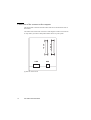
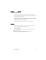
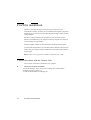
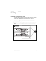
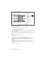
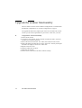
Océ CS40xx
scanners
Installation Manual
Océ-Technologies B.V.
Trademarks
Products in this manual are referred to by their trade names. In most, if not all
cases, these designations are claimed as trademarks or registered trademarks of
their respective companies.
Safety information
This manual contains the following safety information:
Where applicable, cautions and warnings are used throughout this manual to
draw your attention to safety precautions to be taken.
Warning: This is a Class A product. In a domestic environment this product
may cause radio interference in which case the user may be required to take
adequate measures.
Copyright
© 2003 Océ-Technologies B.V. Venlo, The Netherlands
All rights reserved. No part of this work may be reproduced, copied, adapted,
or transmitted in any form or by any means without written permission from
Océ.
Océ-Technologies B.V. makes no representation or warranties with respect to
the contents hereof and specifically disclaims any implied warranties of
merchantability or fitness for any particular purpose.
Further, Océ-Technologies B.V. reserves the right to revise this publication and
to make changes from time to time in the content hereof without obligation to
notify any person of such revision or changes.
Edition 10-2003
GB
Contents
Chapter 1
Introduction
System overview 6
Prerequisites 6
Scanner features 7
Operating modes 8
Scanner configurations 9
Chapter 2
Scanner installation
Prerequisite 12
A first look at the scanner 13
Front view 13
Rear view 14
SCSI installation 15
SCSI connection precautions 15
SCSI board installation 15
Connection of the scanner to the computer 16
SCSI address setup 17
Default SCSI setup 18
Troubleshooting and test switches 19
Power supply connection 20
USB installation 21
USB port 21
Connection of the scanner with the USB cable 23
Unknown device message 23
FireWire installation 24
Connect the scanner with the Firewire cable 24
Unknown device message 27
Software installation 28
Chapter 3
Scanner operation
Scanner control panel 30
Paper ready 31
Inserting a document 32
Contents
3
Insertion slot 32
Scanning thick media 34
Manual adjustment for thick media 34
Automatic adjustment (ATAC) 36
Chapter 4
Scanner maintenance
Scanner maintenance 38
Cleaning 39
Remove the original pressure platen 39
Clean the scanning area 41
Replace the white reference platen 41
Camera alignment 43
Upgrade the scanner functionality 44
Appendix A
Safety information
General safety information 46
Radio interference 46
Symbols 46
Instructions for safe use 47
Appendix B
Miscellaneous
Notation conventions 50
Reader’s comment sheet 51
Addresses of local Océ organisations 53
Index 55
4
Océ CS40xx Installation Manual
Océ CS40xx scanners
Installation Manual
Chapter 1
Introduction
This Installation manual describes the features of the Océ
CS40xx scanners.
■ System overview
■ Scanner configurations
5
System overview
The Océ CS40xx scanners wide format scanners offer solutions for large
format, high volume scanning in colour or graytone mode.
The scanners have fluorescent lighting and individual adaptive light
compensation on each pixel.
They support up to three interface options according to the scanner model:
■
■
■
USB interfacing for easy connectivity (see ‘USB installation’ on page 21).
USB + Standard SCSI interface
SCSI + FireWire.
Prerequisites
■
PC or supported workstation with Win 98, 98SE, ME, NT4, 2000 or XP
(with SCSI or USB) and Win ME, 2000 or XP (with FireWire).
Attention: USB and FireWire are not supported on Windows NT.
FireWire port enabled, USB port or SCSI interface-kit matching the
workstation.
■ The Scanner Maintenance Kit CD supplied with your scanner to install the
scanner drivers, Océ Scanner Agent and Scanner maintenance.
Note: These must be installed before setting up the scanner. Refer to the
Scanner Maintenance user manual for more information.
■ The Scanner Maintenance Kit.
■
6
Océ CS40xx Installation Manual
Scanner features
The Océ CS40xx scanners comprises the following features:
■
■
■
■
■
■
■
■
■
■
■
Media thickness up to 0.6” (15 mm)
Variable resolution in one-dpi increments
Individual tone adjustment for each colour channel (RGB) via gamma and
black and white point correction
All-digital cameras to ensure minimum noise
Colour and monochrome 2-D sharpening and softening filters to enhance
fine details and reduce moiré effects when you scan halftone originals
Colour calibration using the ANSI IT-8 colour reference chart to improve
long term stability of the scanner colour balance, linearity and chromaticity
ICC (International Colour Consortium) profile to support Colour
Management Systems (CMS)
Colour feature extraction to enhance clarity from poor quality originals and
improve details in complex maps and drawings.
Support monochrome graytone capture of 12 bits passing the best 8 bits to
the computer to enhance graytone precision.
Monochrome scanner functions.
Scanning modes from true colour (24-bit RGB) to black and white.
Introduction
7
Operating modes
The Océ CS40xx scanners scanners scans documents in the following colour
and black and white modes:
24 bit RGB colour mode This mode scans images at the full 24-bit true colour
mode for 16.8 million colours.
Indexed colour mode When you scan documents with a limited range of
colours, this mode maps true colours to an indexed colour palette. The scanner
generates this colour palette automatically when it does an adaptive colour
prescan of the original.
The scanner’s ability to transform a true colour image from 16.8 million
colours down to 16 or 256 colours greatly reduces the data volume. At the same
time, the scan speed increases and the disk storage requirements decrease
(needing only 4 bits or 8 bits per pixel, compared with the 24 bits required in
true colour mode).
Feature extracted (classified) colour mode This mode uses colour mapping
to sort the observed colour features in a document and to classify them into
categories using a colour LUT (look up table). You can generate this LUT once
and download it to the scanner for a similar class of documents. Colour
mapping can improve details in complex maps or drawings, while increasing
the scan speed and minimizing disk storage requirements.
Grayscale mode (256 levels) This mode scans the actual gray level of each
pixel, up to 256 levels. Each pixel corresponds to 1 byte (8 bits). The images
scanned in grayscale mode result in files that are 8 times larger than
uncompressed files scanned in lineart mode at the same resolution.
B/W modes (bitmapped, 2-level) This mode reproduces each scanned pixel as
a single bit, either black (1) or white (0), depending on whether its gray level
lies below or above the threshold level. This mode supports both fixed level
and 2-D adaptive thresholding.
B/W copy mode (halftone dither) Converts gray levels of the scanned pixels
into halftones by dithering. This results in very high density line mode files that
are much larger than uncompressed files scanned in line mode at the same
resolution.
8
Océ CS40xx Installation Manual
Scanner configurations
The Océ CS40xx scanners exist in different configurations.
The ‘Smart Card’ gives you the option to upgrade the scanner firmware and
add more functions.
Introduction
9
10
Océ CS40xx Installation Manual
Océ CS40xx scanners
Installation Manual
Chapter 2
Scanner installation
A first look at the Océ CS40xx scanners
SCSI installation
■ USB installation
■ FireWire connection
■ Power supply connection
■ Software installation
■ General recommendations
■
■
11
Prerequisite
Before installing and connecting your scanner, you MUST install the Océ
Scanner Agent software because it contains all the drivers necessary to set up
your system correctly.
▼
Install Océ Scanner Agent
1 Insert the Scanner maintenance kit CD-ROM in your CD driver. The setup
program is launched automatically.
2 Click ‘Install Océ Scanner Agent’.
3 Follow the instructions of the setup wizard.
4 At the end of the installation, the wizard asks if you want to run Océ Scanner
Agent at start-up. Click ‘Yes’ if you want the application to be started
automatically each time you boot your PC.
Note: Note: This is recommended when you define times to power on and
off the scanner automatically in the Timer settings (see ‘Timer settings’ on
page 13).
5 Click ‘Finish’ to exit the setup program. The Océ Scanner Agent icon appears
on the system tray.
12
Océ CS40xx Installation Manual
A first look at the scanner
This section introduces you to the basic parts of the scanner.
Front view
C
B
F
D
A
E
[1] Scanner front view
Label
Part or component
A
B
C
D
E
Control panel
Scanner cover
Ruler
Document insertion slot
‘Smart card’ holder (slide
streamer to the left for access)
Streamer
F
Scanner installation
13
Rear view
At the rear of the scanner, you can locate, according to the printer model:
The USB connector
The USB and SCSI connectors (left)
■ The SCSI and the FireWire connectors
Note: There is also an AUX connection meant for future service purposes.
■
■
■
The ‘on/off’ button and power connector (right)
S
C
S
I
USB
S
C
S
I
AUX
[2] Scanner rear view
14
Océ CS40xx Installation Manual
SCSI installation
On PC-DOS or compatible computers running Windows 98/ME/2000/XP or
Windows NT 4.0, you must first install the SCSI board before you connect the
scanner to your computer.
SCSI connection precautions
■
■
■
Power off your system, your scanner, and all peripheral devices before you
connect or disconnect SCSI cables. Failure to do this may result in a system
crash and, in some cases, destruction of data on your hard disk.
If the scanner is the last device on the SCSI bus, turn on the built-in active
SCSI terminator (switch 4). Otherwise make sure you turn this switch off. Do
not connect any other terminator on the unused SCSI connector, since switch
4 already specifies termination.
The total length of all SCSI cables must be less than 4 meters.
SCSI board installation
Attention: Use only the SCSI board provided with the scanner. Do not
connect any other SCSI device to the same SCSI board.
▼
To install the SCSI board on the computer
1 Power off computer unit and all peripherals, such as diplays or printers.
2 Unplug the computer and peripherals from the electrical outlet.
3 With a screwdriver, loosen the screws to remove the computer cover. Remove
the top cover to expose the extension slots.
4 Choose a free extension slot. Loosen and remove the screw to the back panel.
5 Holding the SCSI board by its metal support bracket, align and press the board
firmly into the extension slot.
6 Use the back panel screw to secure the board to the computer frame (Put the
cover of the computer back on only after having completed the configuration).
7 For the SCSI driver installation under Windows 98/ME/2000/XP and Windows
NT, please refer to the documentation delivered with your SCSI package.
Scanner installation
15
Connection of the scanner to the computer
The SCSI cable connectors and the USB connector are located at the rear of
the scanner.
One of the SCSI connectors is used for connecting the scanner. The extra one
is only used if you want to daisychain another device to your system.
S
C
S
I
USB
[3] SCSI and USB connectors
16
Océ CS40xx Installation Manual
S
C
S
I
AUX
▼
To connect the scanner to the computer
1 Check at the back of the scanner for the SCSI termination. If the scanner is the
last device on the SCSI bus, turn on switch 4, the built-in active SCSI
termination. If the scanner is not the last device, make sure switch 4 is off.
Attention: Do not turn on switch 4 and use a terminator block at the same
time.
2 Switch off your computer and your scanner.
3 Disconnect the power cord.
4 Connect one end of the supplied SCSI cable into the SCSI board connector at
the back of the computer.
5 Connect the other end of the SCSI cable to one of the two SCSI connectors on
the back of the scanner.
6 Set up the scanner SCSI address.
SCSI address setup
You set the SCSI device number on the DIL switch behind the scanner.
▼
To set up SCSI device address
1 Power off the computer and the scanner.
2 To locate the DIL switch, slide the streamer on the front of the scanner to the
left.
3 Press the ‘Push’ button to slide out the ‘smart card’ holder.
4 Remove the ‘smart card’ to access the switch.
Note: Remember to replace the ‘smart card’ before you turn the scanner
back on.
5 Select an unused SCSI device address number according to the table below.
no.
Switch
1
2
3
4
5
6
7
8
0
1
•2
ON
OFF
ON
ON
ON
OFF
ON
ON
ON
ON
OFF
OFF
X
X
X
3
4
5
6
7
OFF
ON
OFF
ON
OFF
OFF
ON
ON
OFF
OFF
ON
OFF
OFF
OFF
OFF
-
OF
F
-
-
-
X
X
X
X
X
SCSI device
Scanner installation
17
SCSI device
no.
Switch
1
2
3
4
5
6
7
8
SCSI-0
built-in
termination
SCSI-0
synch.
transfer
off
SCSI-1
synch.
transfer
off
Force
boot
start up
Continuous test
mode
-
-
-
ON
-
-
-
X
X
-
-
-
-
OF
F
-
-
X
-
-
-
-
-
OFF
-
OF
F
-
-
-
-
-
-
OFF
X
-
-
-
-
-
-
-
OF
F
6 Verify that none of the troubleshooting and test switches (5,6,7,8) are on.
7 Power on the scanner, then the computer.
Default SCSI setup
The factory default SCSI settings are as follows:
OFF ON
1
2
3
4
5
6
7
8
18
Océ CS40xx Installation Manual
Troubleshooting and test switches
For normal scanner use, verify that switches 5, 6, 7, and 8 (troubleshooting and
test switches) are OFF.
Switch 5. SCAN-SCSI (connectors 0A and 0B): When ON, it disables
SCAN-SCSI synchronous transfer mode (reverts to asynchronous transfer).
Use this mode only for testing because it slows down the scanner.
Switch 6. COPY-SCSI (connector 1): When ON, it disables COPY-SCSI
synchronous transfer mode (reverts to asynchronous transfer). Use this mode
only for testing because it slows down the scanner.
Switch 7. Force boot start up: If a malfunction occurs during an update of the
scanner firmware, this switch forces the scanner into firmware boot mode,
enabling you to download the firmware again.
Switch 8. Continuous test mode: You should never use this switch, which is
reserved for testing only by qualified maintenance personnel. The scanner is
inaccessible.
Scanner installation
19
Power supply connection
The Océ CS40xx scanners use a grounded 3-prong power cord to connect to a
grounded power outlet with a maximum 16-ampere protection.
Your electrical installation must comply with IEC 364 standards and the
national standards of your country.
▼
To connect the scanner to the power supply
1 Locate the power connector at the back of your scanner.
2 Plug one end of the power cord delivered with the scanner into the connector.
3 Plug the other end of the cord into the electrical outlet.
4 Turn the ON/OFF switch to ON.
The warm-up indicator on the scanner control panel lights up and remains lit
while the scanner performs various internal diagnostic tests. When fully
powered on, the Power-on indicator stays lit continuously.
20
Océ CS40xx Installation Manual
USB installation
USB (Universal Serial Bus) is a connectivity specification that allows
computer peripherals to be attached to a computer. Users can install hardware
without rebooting their computers.
USB allows up to 127 devices to run at the same time on the bus, with hubs
connecting devices to the bus. The USB 1.1 bus provided with your scanner
supports a data transfer speed of 12Mbps.
USB is supported on Windows 98 or above but not on Windows NT.
USB port
Even if the computer includes a USB port, it will not function unless it is
enabled. Follow the instructions below to check it.
▼
Check your USB port
1 From the Windows ‘Start’ menu, select ‘Settings’ and ‘Control Panel’.
2 Double-click ‘System’.
3 Find ‘Device manager’ (‘Device manager’ or ‘Hardware’ tab).
4 Double-click ‘Universal Serial Bus controllers’:
Scanner installation
21
5 If a USB host controller or root hub is listed, your USB port is enabled. If
nothing is listed, refer to your computer’s documentation.
22
Océ CS40xx Installation Manual
Connection of the scanner with the USB cable
Before connecting the scanner, make sure:
■
■
▼
the USB port is enabled (see page 21)
the scanner drivers are installed. These drivers are on the Scanner
maintenance kit CD and are automatically installed during the Océ Scanner
Agent installation (refer to the Scanner Maintenance user manual for more
details).
To connect the scanner to the computer
1 Locate the USB cable delivered with the scanner.
2 Connect the PC end to a USB port on your computer.
3 Connect the peripheral end to the USB connection socket on the scanner.
▼
To check the installation
1 From the Windows ‘Start’ menu, select ‘Programs’.
2 Launch ‘Scanner Maintenance’.
3 The program detects the scanner and displays the introduction screen.
4 If the scanner is not installed properly, a message is displayed to inform you
that no scanner could be detected.
5 If so, turn off power to all connected devices and reboot the system.
Unknown device message
If your system has problems detecting the scanner, make sure your USB port
is enabled (see page 21).
If your system still does not detect the device:
1 Disconnect the USB cable.
2 Unplug the power to your scanner and turn off the computer.
3 Reconnect the scanner and restart the PC.
4 Restart the driver installation.
Scanner installation
23
FireWire installation
FireWire is currently the fastest connection type for both color and
monochrome scanning. FireWire can accommodate 400 megabits (around 50
megabytes) per second, which is more than adequate for high volume scanning
of large formats.
FireWire is a plug-and-play (PnP) specification. You do however need a
FireWire card installed on your computer and many computers are delivered
with a FireWire card preinstalled.
FireWire capable scanners are delivered with a FireWire board and cable.
To connect through FireWire, you need the FireWire cable that came with your
scanner and your computer must be enabled for FireWire through a FireWire
card and port.
Note: FireWire is not supported on Windows NT, Windows 98 / 98SE.
Connect the scanner with the Firewire cable
You can check if FireWire is enabled on your computer.
▼
Check your computer for FireWire
1 From the Windows ‘Start’ menu, select ‘Settings’ and ‘Control Panel’.
2 Double-click the System icon.
3 Click the Hardware/Device Manager tab.
24
Océ CS40xx Installation Manual
■
If a FireWire host controller (IEEE) is listed, FireWire is enabled on your PC:
■
If you do not see this device listed, you will need to install a FireWire card.
Scanner installation
25
▼
Install a FireWire card
1 Shutdown your computer.
2 Install the card into an empty PCI slot. See your computer™s user™s manual
for installation of new hardware and the driver installation information that
came with your FireWire card to setup the device under your specific Windows
operating system.
FireWire
S
C
S
I
S
C
S
I
FireWire
AUX
[4] FireWire and SCSI connectors
▼
Connect the scanner to the computer
1 Locate the FireWire cable that came with your scanner.
2 Connect the PC end to the FireWire port on your computer.
3 Connect the peripheral end to a FireWire connection socket on your scanner.
4 If you have not yet installed the driver through the Scanner Maintenance Kit
CD , Windows will display the ‘NewHardware Found Wizard’ dialog box after
you connect the cable.
5 If an ‘Unknown device is found’ message appears after you plug in the cable,
follow the steps described below.
6 Follow the installation instructions in the WIDEsystem TOOLS User™s
Guide that came on the WIDEsystem TOOLS CD. The scanner drivers are
installed through an installation wizard.
26
Océ CS40xx Installation Manual
Unknown device message
If your system has problems detecting the scanner, make sure your FireWire
port is enabled (see page 24).
If your system still does not detect the device:
1 Disconnect the FireWire cable.
2 Unplug the power to your scanner and turn off the computer.
3 Reconnect the scanner and restart the PC.
4 Restart the driver installation.
Scanner installation
27
Software installation
For the installation of ‘Océ Scan’, ‘Océ Colour Copy’ and ‘Scanner
maintenance’, please refer to the software’s respective User Manuals or
Installation Guides provided on the documentation CD.
Attention: It is essential that you install Océ Scanner Agent before you
connect the scanner or install any other scanner applications. Indeed, all
drivers are installed with Océ Scanner Agent and help you set up correctly
your system (see ‘Install Océ Scanner Agent’ on page 12).
28
Océ CS40xx Installation Manual
Océ CS40xx scanners
Installation Manual
Chapter 3
Scanner operation
Using the control panel
Inserting a document
■ Scanning thick media
■
■
29
Scanner control panel
The control panel is located on the right hand side of the scanner body.
1
2
3
6
4
7
5
8
[5] Scanner standard control panel
1
2
3
4
5
9
6
7
8
[6] Scanner control panel with ATAC functionality
30
Océ CS40xx Installation Manual
Key/indicator
Function
(1) ‘Power on’
(2) Diagnostic
This indicator lights up when you switch on the scanner.
Blinks when the built-in diagnosis detects an error. When this
indicator blinks at the same time as the “Wait” indicator,
check the camera height alignment.
(3) ‘Wait’ (warm-up) At start-up, this indicator lights up for at least 3 minutes until
the scanner reaches the optimal temperature for operation.
During this time, the scanner performs internal diagnostic
checks. You cannot activate the scanner during this phase.
(4) ‘Ready’
(see ‘Paper ready’ on page 31).
(5) Paper feed
To insert a document in manual mode, press this key to move
the document up to the start position. To eject the document,
press and hold down this key. Scanning automatically stops.
Paper reverse
The paper reverse key stops the scanning process. To move
the document backward through the scanner, press and hold
down this key.
(6) (7) (8)
One-touch scanning buttons. Depending on the installed software, they are used to activate Oce Scan or Oce Colour Copy
(9) ‘ATAC’
Automatic Thickness Adjustment Control.
Paper ready
The Paper Ready Indicator lights up as soon as the drawing is inserted into the
original insertion slot and correctly positioned. Then the original can be moved
into the start-of-scan position either by pressing the Paper Forward Key or
through automatic loading.
■
■
■
■
■
■
The Paper Ready Indicator lights green when ready to scan normal thin
media and yellow when ready for thick media.
The Paper Ready Indicator blinks yellow when the scanner is in ATAC mode
but not yet ready, i.e., the guide plate is not yet positioned.
The Paper Ready indicator stays ON, signifying that the scanner is ready to
be controlled from the computer.
During scanning the Ready indicator will blink.
At end of scanning the Ready indicator will stop blinking signifying that
scanning can be repeated from the computer, or else terminated by ejecting
the original from the scanner.
The paper ready indicator will light red if the guide-plate is in thick media
setting (a raised guide plate) but no media is detected in the scanner. This
applies for a guide-plate raised either manually or through Automatic
Thickness Adjustment Control (ATAC).
Scanner operation
31
Inserting a document
You can insert a document into the scanner right or center-aligned, using
measurements in inches, millimeters, or scanner units. You can make these
settings in the Océ Scan software.
Insertion slot
A ruler at the top of the insertion slot give the width of a right-aligned
document. You can slide out this ruler to switch to or from millimeters and
inches.
■ Markers at the bottom of the insertion slot help you center-align standard size
documents for scanning.
Note: It is preferable to center-align a document to position it
symmetrically on the feed rollers during a scan.
■ You can also measure a document in scanner units.
■
32
Scanner units Media size
Document width
1.4
2
2.6
2.8
3
3.9
4
5.2
5.5
6
7.8
8
11.2
11
11.8
6.0"
8.5"
11.0"
11.9"
12.7"
16.5"
17.0"
22.0"
23.3"
25.4"
33.1"
34.0"
44.0”
46.8”
50.0"
51.5"
Minimum (A5)
A-Size (letter) and near A4
B-Size (11")
A3 (297 mm)
Near A3 and near B-Size
A2 (420 mm)
C-Size and near A2
D-Size (22")
A1 (595 mm)
Near A1 and near D-Size
A0 Portrait (841 mm)
E-Size and near A0
E-Size Landscape
A0 Landscape
Maximum scan width
Maximum media size handled
Océ CS40xx Installation Manual
152 mm
216 mm
280 mm
302 mm
323 mm
420 mm
430 mm
560 mm
592 mm
646 mm
840 mm
862 mm
1118 mm
1189 mm
1270 mm
1310 mm
▼
To insert a document
1 Place your document face down along the edge of the document insertion slot.
2 Press the ‘Paper feed’ key to move the document up to the start position. The
‘Ready’ indicator lights up and blinks intermittently while the document scans.
▼
To eject a document
■
When scanning completes, the ‘Ready’ indicator stops blinking. Press the
‘Paper feed’ key to advance the document to eject it from the scanner.
Scanner operation
33
Scanning thick media
Manual adjustment for thick media
You can adjust the insertion thickness space from 0 to 15 mm (0 to .6”) to
accommodate thick media such as paper board, foam boards, etc.
When you use this setting, keep in mind the following:
■
■
■
■
▼
Extended media thickness reduces the scanning speed. The normal setting
(0) gives the optimal scanning speed.
Extended media thickness can cause variations in the stitching (overlapping
or missing pixels). You can compensate this problem by using a special
stitching setup from the Océ Scan software. (See Océ Scan Online Guide for
details).
Insert the document center-aligned, and support it during the scanning
process.
To prevent image distortion, the scanner by default does not scan leading and
trailing edges of a document with thick media setting. You can turn off this
function from the Océ Scan software.
To adjust the media thickness manually
1 Lift the insertion slot cover.
2 Press down on the right side of the original pressure platen.
3 While holding down the pressure platen, slide the media thickness adjustments
to the desired setting.
4 Release the pressure platen, allowing it to come up and lock into place.
5 Repeat for the left side, checking that the same setting applies to both sides.
6 Close the cover.
34
Océ CS40xx Installation Manual
Setting
Maximum thickness
0 (normal)
1
2
3
4
5
6
7
2 mm (0.08”)
4 mm (0.16”)
6 mm (0.24”)
8 mm (0.32”)
10 mm (0.39”)
12 mm (0.47”)
14 mm (0.55”)
15 mm (0.60”)
E
X
T
E
N
D
E
D
E
X
I
T
0.63
0.55
0.47
0.39
0.31
0.24
0.16
0.08
N
O Inches
R
M
A
L
16
14
12
10
8
6
4
2
E
X
I
T
E
X
T
E
N
D
E
D
N
mm
O
R
M
A
L
[7] Adjusting media thickness
Note: The scanner performs automatic adjustments of the light profile and
stitching only in the normal (0) media thickness setting (2mm/0.08”). When
you use a different thickness setting, the scanner stores and reuses the
last-effected automatic adjustment. Occasionally, you should return to the
normal thickness setting at start-up to allow the scanner to do its automatic
adjustments.
Scanner operation
35
Automatic adjustment (ATAC)
Some scanner models support Automatic Thickness Adjustment Control
(ATAC). They have an ATAC key on their control panel (see page 30). You can
change the insertion slot size on your scanner from 0 to15 mm (0 to 6”).
▼
Adjust the media thickness with ATAC
1 Press the ATAC key on the scanner control panel to set the scanner to ATAC
mode.
2 The ‘Paper Ready’ indicator blinks yellow indicating the scanner is in ATAC
3
4
5
6
36
mode but not ready yet (i.e. the guide plate is not positioned on the thick
original yet).
Press and hold the ‘Paper forward’ key (arrow up) to raise the guide plate until
there is room to insert the thick original.
Insert the thick original evenly for a straight scan path.
Press and hold the ‘Paper reverse’ key (arrow down) to lower the guide plate
until it stops on its own.
The ‘Paper ready’ indicator turns yellow (stop blinking) when the guide plate
is positioned correctly and is ready for thick media scanning.
Note: The scanner leaves automatically the ATAC mode. ‘Paper forward’
and ‘Paper reverse’ keys return to their normal functionality, i.e. moving
the originals forwards and backwards.
Océ CS40xx Installation Manual
Océ CS40xx scanners
Installation Manual
Chapter 4
Scanner maintenance
This chapter describes the three steps of the calibration
procedure handled in the Scanner maintenance software:
■ Cleaning
■ Camera alignment
■ Calibration
It also describes how to upgrade the scanner functionality.
37
Scanner maintenance
The wide format scanners come with a complete set of tools to help you
perform scanner maintenance. This is the Scanner Maintenance Kit.
The Scanner Maintenance Kit includes:
■
■
■
■
■
the scanner maintenance software
the scanner maintenance leaflets
a single maintenance sheet
a protective dust cover
a special cleaning cloth
Thanks to the Scanner Maintenance Kit and especially the Scanner
maintenance software, checking camera alignment and performing calibration
on the Océ CS40xx scanners is much easier and almost automatic.
The scanner maintenance procedure is divided into three consecutive tasks:
■
■
■
Cleaning
Camera alignment
Calibration
The Scanner maintenance wizard will guide through these different steps.
Note: For more details, please refer to the scanner maintenance leaflet
provided in the Scanner Maintenance Kit.
38
Océ CS40xx Installation Manual
Cleaning
Remove the original pressure platen
For routine maintenance tasks, you will need to remove the scanner’s original
pressure platen. This platen is located under the insertion slot cover.
▼
To remove the original pressure platen (non ATAC scanner models)
1 Lift the insertion slot cover.
2 Press down on the right extremity of the platen and with your fingers in (C)
slide the media thickness adjustment completely towards the center of the
platen.
E
X
T
E
N
D
E
D
E
X
I
T
N
O Inches
R
M
A
L
16
14
12
10
8
6
4
2
E
X
I
T
E
X
T
E
N
D
E
D
N
mm O
R
M
A
L
Scanner maintenance
C
39
3 The lock pin D is now visible.
E
X
T
E
N
D
E
D
E
X
I
T
N
O Inches
R
M
A
L
D
16
14
12
10
8
6
4
2
E
X
I
T
E
X
T
E
N
D
E
D
N
mm O
R
M
A
L
4 Repeat for the left extremity of the platen. Both sides of the platen are now
separated from the scanner.
5 Lift the platen up to remove it.
6 Place the platen on the top of the document insertion area.
▼
To replace the original pressure platen
1 Put the original platen back in its operating position by first inserting the right
hand side of the plate.
Note: A sticker labeled ‘back’ shows you the rear side of the platen.
2 Press down the platen and press down on the locking pin to snap the platen into
place.
3 Repeat for the left side of the platen.
4 Close the cover.
▼
To remove the original pressure platen (ATAC scanner models)
1 Push down the two lever buttons found near the insertion slot on each side of
the scanner’s top cover. The cover locking mechanism should now be
disengaged.
2 Hold both levers down and place your free fingers in the insertion slot.
3 Flip the cover open. The pressure platen with the white metal areas is under the
scanner cover.
4 Hold the cover open as you clean.
40
Océ CS40xx Installation Manual
Clean the scanning area
You can clean the scanning area occasionally to remove residual paper dust. To
access the scanning area, you first remove the original pressure platen.
▼
To clean the scanning area
1 Switch the power off and disconnect the power cord.
2 Remove the original pressure platen as described.
3 Carefully wipe clean the glass plate with a cleaning solution suitable for
computer peripherals.
4 Put the guide plate back in its operating position as described.
▼
To clean the bottom side of the glass plate
1 Switch the power off and disconnect the power cord.
2 Remove the original pressure platen as described.
3 Locate a tab at each extremity of the glass plate.
4 Lift the tab upwards. The glass plate swings up, and its bottom side is
accessible.
5 Clean the bottom side with a lint-free cloth.
Attention: Do not spray any solution on this area, or allow any liquid to
reach the internal optics. Do not let any object fall inside this area.
6 Holding the tab, push the glass plate back into position.
7 Replace the original pressure platen as described.
Replace the white reference platen
After long periods of continuous scanning, we recommend that you change the
white reference platen in order to maintain consistently high quality scans.
▼
To replace the white reference plate
1 Switch the power off and disconnect the power cord.
2 Remove the original pressure platen as described.
3 With a screwdriver, remove the two screws located at the extremity. Take care
not to lose the two small washers.
4 Remove the angle bracket.
5 Turn over the original pressure platen.
6 Gently slide the white reference plate horizontally out of its lodging.
Scanner maintenance
41
[8] Removing the white reference plate
7 Replace with a new platen by slowly sliding it back into its lodging.
8 Replace the metal angle bracket with the two screws and washers to secure the
reference platen in its lodging.
9 Replace the original pressure platen as described.
42
Océ CS40xx Installation Manual
Camera alignment
Following the scanner installation, you carry out an initial camera alignment
from the Scanner maintenance software. Thereafter, you only need to perform
this alignment depending on your needs after repeated scanning.
You must let the scanner reach the appropriate operating temperature before
making this adjustment (2 hours after you switch on the scanner). This
operation requires the scanner maintenance sheet provided in the Scanner
Maintenance Kit.
■
■
some models have a single fixed camera. Therefore, they do not require
camera alignment. The maintenance wizard will automatically detect the
scanner model and skip the camera alignment step.
Some models have two cameras, A, B starting from the right side of the
scanner. One is fixed and the other is adjustable.
The procedure below requires that you have installed the Scanner maintenance
software before.
▼
To check the camera height (only for 2 and 4-cameras models)
1 Switch on the scanner and wait two hours for it to reach the optimal
temperature.
2 From the Windows ‘Start’ menu, select ‘Programs’ and start ‘Scanner
maintenance’. The maintenance wizard is launched.
3 Click ‘Next’.
4 Insert the scanner maintenance sheet face down into the scanner, lining up the
arrow at the center insertion point. The program immediately analyses the
alignment and stitching of the cameras. If cameras are unaligned, the program
will automatically make the necessary corrections.
5 Once the camera alignment is checked, the program moves automatically to
basic calibration.
Basic calibration ensures stable and clean scans by reducing noise and
unwanted effects caused by dust particles.
This operation still requires the use of the scanner maintenance sheet. The
program performs autaomatically the basic calibration and then moves to
Colour calibration to ensure long term stability of the linearity, colour balance,
and chromacity of your scans. You need to repeat this operation only about
once every two months of continuous scanning, or when the quality of scanned
colours becomes unsatisfactory.
Scanner maintenance
43
Upgrade the scanner functionality
The Océ CS40xx scanners exists in different configurations. For details about
the different configurations, see ‘Scanner configurations’ on page 9.
You upgrade the firmware by replacing the ‘smart card’ located in the scanner.
Contact your Océ sales representative to procure the ‘smart card’ you want.
▼
To upgrade the scanner functionality
1 Switch off the scanner.
2 At the front of the scanner, locate a streamer with the Océ name. At the left
extremity you will find a small tab.
3 Pull on this tab towards the left. The ‘smart card’ holder becomes visible.
4 Push on the holder as indicated to access the ‘smart card’. You may need to pull
the holder out slightly to remove the ‘smart card’.
5 Replace with a new card.
6 Push the holder back into place.
7 Slide back the streamer.
8 Switch on the scanner and wait unitl it indicates ‘Ready’.
44
Océ CS40xx Installation Manual
Océ CS40xx scanners
Installation Manual
Appendix A
Safety information
45
General safety information
For questions about Océ products which are related to health, safety and the
environment, please contact your Océ organisation at the address listed in the
last appendix of this manual.
Radio interference
Note: This equipment has been tested and found to comply with the limits for a
class A device, pursuant to part 15 of the FCC Rules. These limits are designed
to provide reasonable protection against harmful interference when the
equipment is operated in a commercial environment. This equipment
generates, uses, and can radiate radio frequency energy and, if not installed
and used in accordance with the user manual, may cause harmful interference
to radio communications. Operation of this equipment in a residential area is
likely to cause harmful interference in which case the user will be required to
correct the interference at his own expense.
FCC = Federal Communications Commission.
Symbols
Stickers with the following illustrations are used in this machine to indicate
parts which should not be touched due to high voltage or extreme heat, or parts
which require extra attention:
Symbol
Meaning
Caution, high voltage
Caution, high temperature
Caution
46
Océ CS40xx Installation Manual
Instructions for safe use
Attention: Products designed by Océ are developed and tested in
conformance with the strictest international safety standards. However, to
help assure the safe operation of these products, it is important that:
■
■
You carry out maintenance only as far as prescribed in this manual.
You observe the following safety recommendations:
Maintenance
■
■
■
■
Do not remove any screws from fixed panels.
Do not place any liquids on the machine.
Use maintenance materials or other materials for their original purpose only.
Keep maintenance materials away from children.
To avoid damage and the risk of personal injury, all modifications to Océ
equipment are strictly reserved for properly qualified and trained service
technicians.
Power connection
■
■
■
■
■
■
■
■
Do not move the machine yourself, but contact your Customer Service.
If unforeseen circumstances force you to re-install the machine without the
assistance of Océ Service, make sure that the machine is connected to a
power outlet which is equipped with a fuse or circuit breaker with the
appropriate capacity.
Do not bridge any mechanical or electrical circuit breakers.
Do not use an extension cord to connect the machine.
It is recommended to connect only those copy-control products (or other
products) which meet the (inter)national product safety and radio frequency
interference standards, and to use an attachment cable as specified by Océ.
This equipment is not designed for connection to an IT power system. (An
IT power system is a voltage network in which the neutral wire is not
connected to earth.)
For equipment connected via a wall outlet: place the machine close to an
easily accessible wall outlet.
For equipment connected to the electrical system via a permanent
connection: make sure that the disconnect device in the permanent
connection is easily accessible.
47
Ventilation and location
■
■
■
■
■
■
Do not block the ventilation openings of the machine.
Make sure that the machine is placed on a level, horizontal surface which is
strong enough to bear the full weight of the machine. See the Océ CS40xx
scanners safety data sheet in this appendix for information about the weight
of the machine.
Make sure that there is sufficient space around the machine. This facilitates
both proper loading of materials and equipment maintenance.
Do not place the machine in a room which is subject to excessive vibration.
Do not place the machine in a room that is too small and insufficiently
ventilated. See the Océ CS40xx scanners safety data sheet in this appendix
for information about space and ventilation requirements.
Take care that the machine is placed in rooms according to the environment
conditions as mentioned in the Safety Data Sheet.
General
■
■
48
Always use materials recommended by Océ and developed for this Océ
machine. Materials not approved by Océ may cause damage to your
machine.
Do not use the machine if it is making unusual sounds. Remove the plug from
the power outlet or turn off the switch in the fixed connection to the electrical
system and contact Service.
Océ CS40xx Installation Manual
Océ CS40xx scanners
Installation Manual
Appendix B
Miscellaneous
49
Notation conventions
There are a number of notation conventions used in this manual. This
consistent style enables you to quickly become conversant with the use of this
manual and consequently the Océ CS40xx scanners.
Description Each section or subsection contains a description of the feature or
operation identified in the title. It might also include possible applications, as
well as any guidelines that you should bear in mind.
Procedures A description is followed by a procedure. A procedure always
begins with a phrase which briefly describes the procedure, followed by a
series of numbered steps that take you, step by step, through all phases of
performing the operation.
Figures and tables Figures and tables are titled and numbered sequentially
throughout this manual. Figures include pictures of product components,
screendumps, examples, and diagrams of concepts discussed in the
description.
Attention getters There are several types of information to which we draw
your attention. This information is classified as follows:
Note: In a ‘Note’, information is given about matters which ensure the proper
functioning of the machine or application, but useful advice concerning its
operation may also be given.
Attention: The information that follows ‘Attention’ is given to prevent
something (your copy or original, the copier or printer, data files etc.)
being damaged.
Caution: The information that follows ‘Caution’ is given to prevent you
suffering personal injury.
50
Océ CS40xx Installation Manual
Reader’s comment sheet
Have you found this manual to be accurate?
❏ Yes
❏ No
Could you operate the product after reading this manual?
❏ Yes
❏ No
Does this manual provide enough background information?
❏ Yes
❏ No
Is the format of this manual convenient in size, readability and arrangement
(page layout, chapter order, etc.)?
❏ Yes
❏ No
Could you find the information you were looking for?
❏ Always
❏ Most of the times
❏ Sometimes
❏ Not at all
What did you use to find the required information?
❏ Table of contents
❏ Index
Are you satisfied with this manual?
❏ Yes
❏ No
Thank you for evaluating this manual.
If you have other comments or concerns, please explain or suggest
improvements overleaf or on a separate sheet.
51
Comments:
------------------------------------------------------------------------------------------------------------------------------------------------------------------------------------------------------------------------------------------------------------------------------------------------------------------------------------------------------------------------------------------------------------------------------------------------------------------------------------------------------------------------------------------------------------------Date:
This reader’s comment sheet is completed by:
(If you prefer to remain unknown, please do fill in your occupation)
Name:
Occupation:
Company:
Phone:
Address:
City:
Country:
Please return this sheet to:
Océ-Technologies B.V.
For the attention of ITC User Documentation.
P.O. Box 101,
5900 MA Venlo
The Netherlands
Send you comments by E-mail to : [email protected]
For the addresses of local Océ organizations see : www.oce.com
52
Océ CS40xx Installation Manual
Addresses of local Océ organisations
Océ-Australia Ltd.
P.O.Box 196
Cheltenham VIC 3192
Australia
Océ-Hungária Kft. P.S.
1241 Budapest, P.O.B. 237
1135 Budapest, Hun u. 2
Hungary
Océ-Österreich GmbH
Postfach 95
1233 Vienna
Austria
Océ-Italia S.P.A.
Via Cassanese 206
20090 Segrate, Milano
Italia
Océ-Belgium N.V./S.A.
Avenue J.Bordetlaan 32
1140 Brussel
Belgium
Océ Asia Pte. Ltd. P.S.
P.O. Box 1260
2 Kallang Sector, 7th floor
SIN-349277
Singapore
Océ-Česká republika s.r.o.
K. Rysánce 16
14754 Praha 4
Czech Republic
Océ-Danmark A.S.
Kornmarksvej 6
DK 26605 Brøndby
Denmark
Océ-France S.A.
“La Brèche”
3, Rue des Archives
F-94000 Créteil
France
Océ Printing Systems GmbH
Siemensallee 2
85586 Poing
Germany
Miscellaneous
Océ Printing Systems SA (Pty) Ltd.
P.O. Box 3149
Johannesburg 2000
South Africa
Océ-Nederland B.V.
P.O.Box 800
5201 AV ‘s-Hertogenbosch
The Netherlands
Océ Norge A/S
Postboks 53, Grefsen
N-409 Oslo 4
Norway
Océ España SA
Business Park MAS BLAU
C/Osona 2, 2-3a Planta
08820 El Prat del Llobregat (Barcelona)
Spain
53
Océ-Svenska AB
P.O.box 754
S-191 27 Sollentuna
Sweden
Océ Printing Systems
Obstgartenstrasze 25
CH-8302 kloten
Switserland
Océ Printing Systems U.K.Ltd.(Loughton)
Langston Road, Loughton
GB-Esses IG10 3TH
United Kingdom
Océ Printing Systems U.K.Ltd.(Bracknell)
Siemens Nixdorf House Oldbury
Bracknell, Berks RG12 4FZ
United Kingdom
Océ-USA Inc.
5450 North Cumberland Av.
Chicago, Ill. 606556
U.S.A.
Océ Printing Systems USA
5600 Broken Sound Blvd
Boca Raton, FI 33487
USA
54
Océ CS40xx Installation Manual
Index
Scanner control panel 30
Scanner Maintenance Kit 38
Scanning thick media 34
SCSI installation 21
System overview 6
A
ATAC 31, 36
Automatic adjustment 36
W
White reference platen
replacing 41
F
FireWire 24
Firmware configurations 9
I
Inserting a document 32
M
Maintenance
cleaning scanning area 41
O
Océ CS 4050
system overview 6
Operating modes 8
Original pressure platen
removing 39
S
safety information 47
Scanner
configurations 9
features 7
front view 13
operating modes 8
rear view 14
Index
55