1
FINAL YEAR PROJECT REPORT
NE T W O R K A S SE T S M O N IT O R IN G A ND
SE C U R I T Y U S I NG S N M P
Project By:
Imran Shabbir
M. Asif Ahmed Khan
M a s te r o f C o m p u te r S c i en c e
TABLE OF CONTENTS
Title
I
Submission Performa
II
Abstract
III
Acknowledgement
IV
List of Tables
V
List of Figures
VI
CHAPTERS:
1
INTRODUCTION
1.
Background Review
2
1.2.1
SNMP Overview
2
1.2.2
Before and After SNMP
3
1.2.3
SNMP and UDP
4
1.2.3.1
Application
6
1.2.3.2
UDP
6
1.2.3.3
IP (Internet Protocol)
6
1.2.3.4
Medium Access Control (MAC)
6
1.2.4
SNMP Communities
7
1.2.5
SNMP OPERATIONS
8
1.2.5.1
The get operation
8
1.2.5.2
The get-next operation
9
1.2.5.3
The get-bulk operation
10
1.2.5.4
Get-bulk request sequence
11
1.2.5.5
The set Operation
11
1.2.5.6
Set request response
12
1.2.5.7
SNMP Traps
12
1.2.6
1.2.7
RFCs and SNMP Version
13
1.2.6.1
SNMP Version 1
14
1.2.6.2
SNMP Version 2
14
1.2.6.3
SNMP Version 3
14
Structure Management Information
14
1.2.7.1
14
The Structure of Management Information
1.2.8
1.2.9
2
1.2.7.2
Naming OIDs
15
1.2.7.3
SMI object tree
16
MIB (Management Information Base)
17
1.2.8.1
18
CLOSER Look at MIB-II
ASN.1 (Abstract Syntax Notation One)
20
PROJECT PLANNING & MANAGEMENT
2.1
Team Organization
22
2.2
Resources
23
2.3
Team Structure
23
2.4
Network Diagram
24
2.5
List Of Tasks
24
2.6
Project Planning
26
3 AIMS AND OBJECTIVES
4
3.1
Aims and Objective
27
3.2
System Diagram
28
3.3
Scope of Project
29
3.4
Project Overview
29
ANALYSIS AND DESIGN
4.1
Data Collection
30
4.2
External Interface Requirements
30
4.3
Use Case Model
30
4.4
System level use-case diagram
31
4.5
Use Cases
31
4.6
User Documentation
36
4.7
Algorithm
36
4.8
Data Flow Diagram
37
4.9
Entity Relationship Diagram
38
4.10 Software Process Model
5
39
FEASIBILITY ANALYSIS
5.1
5.2
Technical Feasibility
41
5.1.1
41
Feasible / Alternate Solution
Operational Feasibility
42
6
7
IMPLEMENTATION
6.1
Agents Discovery
45
6.2
Agent System Information
48
6.3
Update Information
49
6.4
Communication b/w Administrator and Agents
51
TESTING
7.1
Test cases
53
7.2
Results
57
8
CONCLUSIONS
58
9
FUTURE WORKS
59
10
REFERENCES
60
APPENDIX A
A-1
APPENDIX B
B-1
APPENDIX C
C-1
APPENDIX D
D-1
P ERFORMA FOR S UBMISSION L ETTER
Name:
1. Imran Shabbir
2. M. Asif Ahmed Khan
Address:
1. G-36/2 Block B, North Nazimabad, Karachi
2. House No. 544, Sector - 5 / E, Orangi, Karachi
Title of Report: N ETW O R K A SS E TS M O N I TO R IN G
AND
S EC U R ITY
U SIN G
SNMP
Project Supervisor: Sir Farhan
This report is submitted as required for the project in accordance with the rules laid down by
the Federal Urdu University for Arts, Science & Technology as part of the requirements for
the award of the degree of Masters of Computer Science (MCS). We declare that the work
presented in this report is our own effort where due reference or acknowledgement is given to
the work of others.
Date:- _________________
Signature of students:
1. _________________
Imran Shabbir
2. _________________
M. Asif Ahmed Khan
Signature of Supervisor:
Date:-_________________
_____________________
Sir Farhan
II
A CKNOWLEDGEMENT
Primarily, we are thankful to Allah for giving us the strength and ability to complete this
project successfully; Our Parents for their support, encouragement and cooperation in every
walk of life.
We would also like to thank our Company Director, Mr. Nabeel Bari and Head of our
Department, Naeem Siraj who provided us with all the technical facilities and resources.
Their cooperation throughout the project development was of great help in accomplishment
of our objective.
We are also extremely grateful to our Senior Faculty members who were of great help for our
Survey (Data Collection). They took out time and enlightened us with their ideas and views.
Their guidance means a lot to us.
It was with the help, guidance and cooperation of these people that we were able to achieve
our objectives successfully.
III
A BSTRACT
Learning is the process whereby people acquire new skill or knowledge to enhance their
working and academic performance. The important role of education towards the success of
the economy cannot be underestimated as it brought about a new arena of Digital Learning,
which is solution to training problems and challenges to the organizations.
This Project is about Network Assets Monitoring and Security Software using SNMP. We
developed a client sever based application which mainly performs the following tasks:
Monitors the networking devices-switches and routers etc.
Does the asset management of networked devices—PCs, printers, scanners, networking
devices and any SNMP enabled device may it be even a refrigerator or a heating system.
This application facilitates the job of the network administrator, who does not necessarily
need to have an awareness of using such tools by providing user-friendly interface, which can
easily be related to the way in which such tasks are performed.
Network Assets Monitoring and Security Software using SNMP can also be used in various
other industries where the security of networked equipment is necessary.
IV
L IST OF TABLES
Table No.
Table Detail
Page No.
Table 1
Project Overview
29
Table 2
Feasibility Report
41
Table 4.5.1
View Reports
31
Table 4.5.2
Scan Network and update Database
32
Table 4.5.3
Make User
33
Table 4.5.4
Update Member
33
Table 4.5.5
Delete Member
34
Table 4.5.6
Change Workstation Profile
34
Table 4.5.7
View Database
35
Table 4.5.8
Scan Respective Network and Update Data
35
Table 3
Login Screen test
53
Table 4
SNMP Explorer Screen test
54
Table 5
SNMP Manager Screen test
54
Table 6
Searching Screen Test
55
Table 7
Agent Screen Test
56
Table C-1
Resource Allocation
C-I
V
L IST OF F IGURES
Figure No.
Figure Detail
Page No.
Figure 1 A
A SNMP Architecture
5
Figure 1 B
Get Operation
8
Figure 1 C
Get Next Operation
10
Figure 1 D
Get Bulk
11
Figure 1 E
Set Operation
11
Figure 1 F
SNMP Trap
12
Figure 1 G
Naming OIDs
16
Figure 1 H
MIB II tree
19
Figure 2 A
Team Structure Diagram
23
Figure 2 B
Network Diagram
24
Figure 3 A
System Diagram
28
Figure 4 A
Use Case Model
31
Figure 4 B
Data Flow Diagram
37
Figure 4 C
Entity Relationship Diagram
38
Figure 4 D
Component Assembly Model Diagram
39
Figure 5 A
SNMP Manager
42
Figure 5 B
SNMP Agent
43
Figure 5 C
SNMP Manager Explorer
43
Figure 5 D
SNMP Trap Catcher
44
Figure 6.A
Different Module Of Implementation
45
Figure B-1
Splash Screen
B-II
Figure B-2
SNMP Manager Screen I
B-II
Figure B-2 B
Set Value Screen
B-IV
Figure B-3
Get Table
B-IV
Figure B-4
View Trap
B-V
Figure B-5
SNMP Agent Screen
B-VI
Figure B-6
Agents Overview
B-VI
Figure B-7
Trap Start and Catches Trap
B-VII
Figure B-8
SNMP Explorer
B-VIII
VI
NET WORK ASSE T S MONIT ORIN G
AN D
SECURITY
USIN G
SNM P
Chapter 1
Introduction
The major issue of administrator in big organization is hardware management. The work
force of any organization includes hardware, if management of hardware not done properly
then the work force may effect badly. Companies are investing lot of money on hardware
management but they still not getting good results. Why? Because they do not automate it, if
they automate it there will be less chances of error.
Inventory management is one of the main issues of mature industry. We also solve this
problem by introducing auto registry. This system will register the workstation automatically
as it plugged in to the network. If configuration of any hardware changes it will update it after
the authentication of the administrator.
If the location of workstation is changed then administrator can update the system
description, contact information etc. from server.
This report covers all the phases involved in the development of this software. Explaining
each separately, chapter wise. Consists of 7 chapters, covering different aspects of the
project.
Analysis and designing are considered the major phases in the development of any software.
If not done properly, can result in a bad product and non conformance to requirements.
Analysis and designing is given proper attention to avoid major bugs in later stages of
development. Chapter 2 of this report highlights project planning done through data
collection and various other techniques and designing steps for developing the software.
This is followed by chapter 3, which explains aims and objective followed by analysis phase
in chapter 4. Another important area that is usually not paid attention to is feasibility analysis
in terms of technical and operational feasibility has been covered in chapter 5.
Chapter 6 gives the task break up in implementing the software and explains each. Every
software / product is incomplete with out thorough testing. Chapter 7 of this report explains
Federal Urdu University
Page - 1
NET WORK ASSE T S MONIT ORIN G
AN D
SECURITY
USIN G
SNM P
the various important pieces of the software, which were tested, their expected and actual
results. Conclusion and future work in the end terminates the report.
References in the end give the reader, a list of websites, books and people referred in
completing this report / product. The report has been written in a form, which would help the
reader of technical or non technical background in clearly understanding the software and
also as a guide in further enhancing its features.
1.2 Background of Snmp
The background study that has been carried out for proper analysis of SNMP (Simple
Network Management Protocol) is as follows.
1.2.1 SNMP Overview
The Simple Network Management Protocol (SNMP) was introduced in 1988 to meet the
growing need for a standard for managing internet protocol (IP).SNMP provides its user with
a “simple” set of operations that allows these devices to be managed remotely. Many kinds of
devices support SNMP including routers, witches, servers, workstations, printers, modem
racks and uninterruptible power supplies (UPSs). The way you can use SNMP range from the
mundane to the exotic: it’s fairly simple to use SNMP to monitor the health of your routers,
switches and other pieces of network hardwares, but you can also use it to control your
network devices and even send pages or take other automatic action if problem arise.
SNMP usually associated with managing routers, but it’s important to understand that it can
be used to manage many types of devices. While SNMP predecessor, the Simple Gateway
Management Protocol (SGMP) was developed to manage Internet routers, Snmp can be used
to manage UNIX systems, Windows systems, printers, modem racks, power supplies, and
more. Any device running software that allows the retrieval of SNMP information can be
managed. This includes not only physical devices but also software, such as web servers and
databases1.
Another aspect of network management is network monitoring; that is, monitoring an entire
network as opposed to individual routers, hosts, and other devices. Remote Network
Monitoring (RMON) was developed to help us understand how the network itself is
Federal Urdu University
Page - 2
NET WORK ASSE T S MONIT ORIN G
AN D
SECURITY
USIN G
SNM P
functioning, as well as how individual devices on the network are affecting the network as a
whole. It can be used to monitor not only LAN traffic, but WAN interfaces as well.
1.2.2 Before and After SNMP
Let us say that you have a network of 100 machines running various operating systems.
Several machines are file servers, a few others are print servers, another is running software
that verifies credit card transactions (presumably from a web-based ordering system), and the
rest are personal workstations. In the actual network going. A T1 circuit connects the
company to the global internet, and there is a private connection to the credit card verification
system.
What happens when one of the file servers crashes? If it happens in the middle of the
workweek, it is likely that the people using it will notice and the appropriate administrator
will be called to fix it. But what if it happens after everyone has gone home. Including the
administrators, or over the weekend?
What if the private connection to the credit card verification system goes down at 10 p.m. on
Friday and isn’t restored until Monday morning? If the problem was faulty hardware and
could have been fixed by swapping out a card or replacing a router, thousands of dollars in
web site sales could have been lost for no reason. Likewise, if the T1 circuit to the internet
goes down. It could aversely affect the amount of sales generated by individuals accessing
your web site and placing orders.
These are obviously serious problems – problems that can conceivably affect the survival of
your business. This is where SNMP comes in. Instead of waiting for someone to notice for
fixing the problem (which may not happen until Monday morning, if the problem occurs over
the weekend), SNMP allows you to monitor your network constantly, even when you are not
there. For example, it will notice if the number of bad packets coming through one of your
router’s interfaces is gradually increasing, suggestion that the router is about to fail. You can
arrange to be notified automatically when failure seems imminent, so you can fix the router
before it actually breaks. You can also arrange to be notified if the credit card processor
appears to get hung – you may even be able to fix it from home. Moreover, if nothing goes
wrong, you can return to the office on Monday morning knowing there will not be any
surprises1.
Federal Urdu University
Page - 3
NET WORK ASSE T S MONIT ORIN G
AN D
SECURITY
USIN G
SNM P
There might not be quite as much glory in fixing problems before they occur, but you and
your management will rest more easily. We can’t tell you how to translate that into higher
salary – sometimes it’s better to be the guy who rushes in and fixes things in the middle of a
crisis, rather than the guy who makes sure the crisis never occurs. But SNMP does enable you
to keep logs that prove your network is running reliably and show when you took action to
avert an impending crisis1.
1.2.3 SNMP and UDP
SNMP uses the User Datagram Protocol (UDP) as the transport protocol for passing data
between managers and agents. UDP, defined in RFC 786, was chosen over the Transmission
Control Protocol (TCP) because it is connectionless; that is, no end-to-end connection is
made between the agent and the NMS when datagrams (packets) are sent back and forth. This
aspect of UDP makes it unreliable, since there is no acknowledgement of lost datagrams at
the protocol level. It’s up to the SNMP application to determine if datagrams are lost and
retransmit them if it so desires. This is typically accomplished with a simple timeout. The
NMS sends a UDP request to an agent and waits for a response. The length of time the NMS
waits depends on how it’s configured. If the timeout is reached and the NMS has not heard
back from the agent, it assumes the packet was lost and retransmits the request. The number
of times the NMS retransmit packets is also configurable2.
At least as far as regular information requests are concerned, the unreliable nature of UDP
isn’t a real problem. At worst, the management station issues a request and never receives a
respond. For traps, the situation is somewhat different. If an agent sends a trap and the trap
never arrives, the NMS has no way of knowing that it was ever sent. The agent doesn’t even
know that it needs to resend the trap, because the NMS is not required to send a response
back to the agent acknowledging receipt of the trap.
The upside t the unreliable nature of UDP is that it requires low overhead, so the impact on
your network’s performance is reduced. SNMP has been implemented over TCP, but this is
more for special-case situations in which someone is developing an agent for a proprietary
piece of equipment. In a heavily congested and managed network, SNMP over TCP is a bad
idea. It’s also worth realizing that TCP isn’t magic, and that SNMP is designed for working
with networks that are in trouble – if your network never failed, you wouldn’t need to
monitor it. When a network is failing, a protocol that tries to get the data through but gives up
Federal Urdu University
Page - 4
NET WORK ASSE T S MONIT ORIN G
AN D
SECURITY
USIN G
SNM P
if it can’t is almost certainly a better design choice than a protocol that will flood the network
with retransmissions in its attempt to achieve reliability.
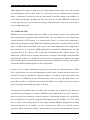
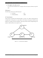
SNMP uses the UDP port 161 for sending and receiving requests, and port 162 for receiving
traps from managed devices. Every device that implements SNMP must use these port
numbers as the defaults, but some vendors allows you to change the default ports in the
agent’s configuration. If these defaults are changed, the NMS must be made aware of the
changes so it can query the device on the correct ports.
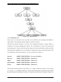
----------- Response to Snmp request sent from the agent to port 161 on the NMS
Figure 1 A SNMP Architecture3.
Shows the TCP/IP protocol suite, which is the basis for all TCP/IP communication. Today,
any device that wishes to communicate on the Internet (e.g., Windows NT systems, UNIX
Servers, Cisco routers, etc.) must use this protocol suite. This model is often referred to as a
protocol stack, since each layer uses the information from the layer directly below it and
provides a service to the layer directly above it.
When either an NMS or an agent wishes to perform an SNMP function (e.g., a request or
trap), the following events occur in the protocol stack 1.
Federal Urdu University
Page - 5
NET WORK ASSE T S MONIT ORIN G
AN D
SECURITY
USIN G
SNM P
1.2.3.1 Application
First, the actual SNMP application (NMS or agent) decides what it’s going to do. For
example, it can send an SNMP request to an agent, send a response to an SNMP request (this
would be sent from the agent), or send a trap to an NMS. The application layer provides
services to an end user, such as an operator requesting status information for a port on an
Ethernet switch.
1.2.3.2 UDP
The next layer, UDP, allows two hosts to communicate with one another. The UDP header
contains, among other things, the destination port of the device to which it’s sending the
request or trap. The destination port will either be 161 (query) or 162 (trap).
1.2.3.3 IP
The IP layer tries to deliver the SNMP packet to its intended destination, as specified by its IP
address.
1.2.3.4 Medium Access Control (MAC)
The final event that must occur for an SNMP packet to reach its destination is for it to be
handed off to the physical network, where it can be routed to its final destination. The MAC
layer is comprised of the actual hardware and device drivers that put your data onto a
physical piece of wire, such as an Ethernet card. The MAC layer also is responsible for
receiving packets from the physical network and sending them back up the protocol stack so
they can be processed by the application layer (SNMP, in this case).
This interaction between SNMP applications and the network is not unlike that between two
pen pals. Both have messages that need to be sent back and forth to one another. Let’s say
you decide to write your pen pal a letter asking if she would like to visit you over the
summer. By deciding to send the invitation. You’ve acted as the SNMP application. Filling
out the envelop with your pen pal’s address is equivalent to the function of the UDP layer,
which records the packet’s destination port in the UDP header; in this case it’s your pen pal’s
address. Placing a stamp on the envelope and putting it in the mailbox for the mailman to
pick up is equivalent to the IP layer’s function. The final act occurs when the mailman comes
to your house and picks up the letter. From here the letter will be routed to its final
destination, your pen pal’s mailbox. The MAC layer of a computer network is equivalent to
Federal Urdu University
Page - 6
NET WORK ASSE T S MONIT ORIN G
AN D
SECURITY
USIN G
SNM P
the mail trucks and airplanes that carry your letter on its way. When your pen pal receives the
letter, she will go through the same process to send you a reply4.
1.2.4 SNMP Communities
SNMPv1 and SNMPv2 use the notion of communities to establish trust between managers
and agents. An agent is configured with three community names: read only, read-write, and
trap. The community names are essentially passwords; there’s no real difference between a
community string and the password you use to access your account on the computer. The
three community strings control different kinds of activities. As its name implies, the readonly community string lets you read data values, but doesn’t let you modify the data. The
read-write community is allowed to read and modify data values; with the read write
community string, you can read the counters, reset their values, and even reset the interfaces
or do other things that change the router’s configuration. Finally, the trap community string
allows you to receive traps (asynchronous notifications) from the agent.
Most vendors ship their equipment with default community strings, typically public for the
read-only community and private for the read-write community. It’s important to change
these defaults before your advice goes live on the network. When setting up an SNMP agent,
you will want to configure its trap destination, which is the address to which it will send any
traps it generates. In addition, since SNMP community strings are sent in clear text, you can
configure an agent to send an SNMP authentication-failure trap when someone attempts to
query your device with an incorrect community string. Among other things, authenticationfailure traps can be very useful in determining when an intruder might be trying to gain
access to your network.
There are ways to reduce your risk of attack. IP firewalls or filters minimize the chance that
someone can harm any managed device on your network by attacking it through SNMP. You
can configure your firewall to allow UDP traffic from only a list of known hosts. For
example, you can allow UDP traffic on port 161 (SNMP requests) into your network only if it
comes from one of your network-management stations. The same goes for traps; you can
configure your router so it allows UDP traffic on port 162 to your NMS only if it originates
from one of the host you are monitoring. Firewalls aren’t 100% effective, but simple
precautions such as these do a lot to reduce your risk4.
Federal Urdu University
Page - 7
NET WORK ASSE T S MONIT ORIN G
AN D
SECURITY
USIN G
SNM P
1.2.5 SNMP OPERATIONS
The Protocol Data Unit (PDU) is the message format that managers and agents use to send
and receive information. There is a standard PDU format for each of the following SNMP
operation.
Get
Get-next
Get-bulk
Set
Trap
1.2.5.1 The get operation
The get request is initiated by the NMS, which sends the request to the agent. The agent
receives the request and processes it to best of its ability. Some devices that are under heavy
load, such as routers, may not be able to respond to the request and will have to drop it. If the
agent is successful in gathering the requested information, it sends a get-response back to the
NMS, where it is processed. This process is illustrated in Figure.
Figure 1 B: Get Operation
How did the agent know what the NMS was looking for? One of the items in the get request
is a variable binding. A variable binding, or varbind, is a list of MIB objects that allows a
request’s recipient to see what the originator wants to know. Variable bindings can be
thought of as OID=value pairs that make it easy for the originator (the NMS, in this case) to
pick out the information it needs when the recipient fills the request and send back a
response11.
Federal Urdu University
Page - 8
NET WORK ASSE T S MONIT ORIN G
AN D
SECURITY
USIN G
SNM P
1.2.5.2 The get-next operation
The get-next operation lets you issue a sequence of commands to retrieve a group of values
from a MIB. In other words, for each MIB object we want to retrieve, a separate get-next
request and get-response are generated. The get-next command traverses a subtree in
lexicographic order. Since an OID is a sequence of integers, it’s easy for an agent to start at
the root of its SMI object tree and work its way down until it finds the OID it is looking for.
When the NMS receives a response from the agent for the get-next command it just issued, it
issues another get-next command. It keeps doing this until the agent returns an error,
signifying that the end of the MIB has been reached and there are no more objects left to get.
The get-next sequence returns seven MIB variables. Each of these objects is part of the
system group as it’s defined in RFC 1213. We see a system object ID, the amount of time the
system has been up, the contact person, etc.
Given that you’ve just looked up some object, how does get-next figure out which object to
look up next? Get-next is based on the concept of the lexicographic ordering of the MIB’s
object tree. This order is made much simpler because every node in the tree is assigned a
number. To understand what this means, let’s start at the root of the tree and walk down to
the system node.
To get to the system group (OID 1.3.6.1.2.1.1). We start at the root of the object tree and
work our way down. (Figure 1 C) shows the logical progression from the root of the tree all
the way to the system group. At each node in the tree, we visit the lowest-numbered branch.
Thus, when we are at the root node, we start by visiting ccitt. This node has no nodes
underneath it, so we move to the iso node. Since iso does have a child we move to that node,
org. the process continues until we reach the system node. Since each branch is made up of
ascending integers (ccitt (0) iso (1) join (2), for example), the agent has no problem
traversing this tree structure all the way down to the system (1) group. If we were to continue
this walk, we’d proceed to system.1 (system.syslocation), system.2, and the other objects in
the system group. Next, we’d go to interfaces (2), and so on1.
Federal Urdu University
Page - 9
NET WORK ASSE T S MONIT ORIN G
AN D
SECURITY
USIN G
SNM P
Figure 1 C: Get Next Operation
1.2.5.3 The get-bulk operation
SNMPv2 defines the get-bulk operation, which allows a management application to retrieve a
large section of a table at once. The standard get operation can attempt to retrieve more than
one MIB object at once, but message sizes are limited by the agent’s capabilities. If the agent
can’t return all the requested responses, it returns an error message with no data.
The get-bulk operation, on the other hand, tells the agent to send as much of the response
back as it can. This means that incomplete responses are possible. Two fields must be set
when issuing a get-bulk command: nonrepeaters and max-repetitions. Nonrepeaters tells the
get-bulk command that the first N objects can be retrieved with a simple get-next operation.
Max-repetitions tells the get-bulk command to attempt up to M get-next operations to retrieve
the remaining objects. Figure 1 D shows the get-bulk command sequence1.
Federal Urdu University
Page - 10
NET WORK ASSE T S MONIT ORIN G
AN D
SECURITY
USIN G
SNM P
1.2.5.4 Get-bulk request sequence
In figure, we are requesting three bindings: sysDescr, ifInOctets, and ifOutOctets. The total
number of the variable bindings that we have requested is given by the formula N+ (M * R),
where N is the number of nonrepeaters (i.e., scalar objects in the request – in this case 1,
because sysDescr is the only scalar object), M is max-repetitions (in this case, we have set it
arbitrarily to 3), and R is the number of non scalar objects in the request ( in this case 2,
because ifInOctets and ifOutOctets are both non scalar). Plugging in the numbers from this
example, we get 1+ (3*2) = 7, which is the total number of variable bindings that can be
returned by this get-bulk request.
Since get-bulk is a SNMPv2 command, you have to tell snmpgetbulk to use a SNMPv2 PDU
with the –v2c option. The nonrepeaters and max-repetitions are set with the –B 1 3 option.
This sets nonrepeaters to 1 and max-repetitions to 3. Notice that the command returned seven
variable bindings: one for sysDescr and three each for ifInOctets and ifOutOctets.
1.2.5.5 The set Operation
The set command is used to change the value of a managed object or to create a new row in a
table. Objects that are defined in the MIB as read-write can be altered or created using this
command. It is possible for an NMS to set more than one object at a time.
Figure 1 E: Set Operation
1.2.5.6 Set request response
Figure shows the set request sequence. It’s similar to the other command, but it is actually
changing something in the device’s configuration, as opposed to just retrieving a response to
a query. If we look at an example of an actual set, you will see the command take place.
Federal Urdu University
Page - 11
NET WORK ASSE T S MONIT ORIN G
AN D
SECURITY
USIN G
SNM P
1.2.5.7 SNMP Traps
A trap is way for an agent to tell the NMS that something bad has happened. Figure shows
the trap-generation sequence.
Figure 1 F SNMP Trap
1.2.5.7.1 Trap generation
The trap originates from the agent and is sent to the trap destination, as configured within the
agent itself. The trap destination is typically the IP address of the NMS. No acknowledgment
is sent from the NMS to the agent, so the agent has no way of knowing if the trap makes it to
the NMS. Since SNMP uses UDP, and since traps are designed to report problems with your
network, traps are especially prone to getting lost and not making it to their destinations.
However, the fact that traps can get lost doesn’t male them any less useful; in a well-planned
environment, they are an integral part of network management. It’s better for your equipment
to try to tell you that something is wrong, even if the message may never reach you, than
simply to give up and let you guess what happened. Here are a few situations that a trap
might report5:
A network interface on the device has gone down.
A network interface on the device has come back up.
An incoming call to a modem rack was unable to establish a connection to a
modem.
The fan on a switch or router has failed.
When an NMS receives a trap, it needs to know how to interpret it; that is, it needs to know
what the trap means and how to interpret the information it carries. A trap is first identified
by its generic trap number. There are seven generic trap numbers (0-6). Generic trap 6 is a
special catch-all category for “enterprise-specific” traps, which are traps defined by vendors
or users that fall outside of the six generic trap categories. Enterprise-specific traps are further
Federal Urdu University
Page - 12
NET WORK ASSE T S MONIT ORIN G
AN D
SECURITY
USIN G
SNM P
identified by an enterprise ID (i.e., an object ID somewhere in the enterprises branch of the
MIB tree, iso.org.dod.internet.private.enterprises) and a specific trap number chosen by the
enterprise that defined the trap. Thus, the object Id of an enterprise-specific trap is enterpriseid.specific-trap-number. For example when Cisco defines special traps for its private MIBs, it
places
them
all
in
its
enterprise-specific
MIB
tree
iso.org.dod.internet.private.enterprises.cisco), you are free to define your own enterprisespecific traps; the only requirement is that you register your own enterprise number with
IANA.
A trap is usually packed with information. As you’d expect, this information is in the form of
MIB objects and their values; as mentioned earlier, these object-value pairs are known as
variable bindings. For the generic trap 0 through 5, knowledge of what the trap contains is
generally built into the NMS software or trap receiver. The variable bindings contained by an
enterprise-specific trap are determined by whoever defined the trap. For example, if a modem
in a modem rack fails, the rack’s agent may send a trap to the NMS informing it of the
failure. The trap will most likely be an enterprises-specific trap defined by the rack’s
manufacturer; the trap’s contents are up to the manufacturer, but it will probably contain
enough information to let you determine exactly what failed (for example, the position of the
modem card in the rack and the channel on the modem card)1.
1.2.6 RFCs and SNMP Version
The Internet Engineering Task Force (IETF) is responsible for defining the standard protocols
that govern Internet traffic, including SNMP. The IETF publishes Requests for Comments
(RFCs), which are specifications for many protocols that exist in the IP realm. Documents
enter the standards track first as proposed eventually approved; the RFC is given standard
status – although there are fewer completely approved standards. Two other standards-track
designations, historical and experimental, define (respectively) a document that has been
replaced by a newer RFC and a document that is not yet ready to become a standard 6.
1.2.6.1 SNMP Version 1
(SNMPv1) is the current standard version of the SNMP protocol. It’s defined in RFC 1157
and is a full IETF standard. SNMPv1’s security is based on communities, which are nothing
more than passwords: plain-text strings that allow any SNMP-based application that knows
Federal Urdu University
Page - 13
NET WORK ASSE T S MONIT ORIN G
AN D
SECURITY
USIN G
SNM P
the strings to gain access to a device’s management information. There are typically three
communities in SNMPv1: read-only, read-write and trap.
1.2.6.2 SNMP Version 2
(SNMPv2) is often referred to as community string-based SNMPv2. this version of SNMP is
technically called SNMPv2c. It’s defined in RFC 1905, RFC 1905, and RFC 1907, and is an
experimental IETF. Even though it’s experimental, some vendors have started supporting it in
practice.
1.2.6.3 SNMP Version 3
(SNMPv3) will be the next version of the protocol to reach full IETF status. It’s currently a
proposed standard, defined in RFC 1905, RFC 1906, RFC 1907, RFC 2571, RFC 2572, RFC
2573, RFC 2574 and RFC 2575. It adds support for strong authentication and private
communication between managed entities3.
1.2.7 Structure Management Information
The Structure of Management Information (SMI) provides a way to define managed objects
and their behavior. An agent as in its possession a list of the objects that it tracks. One such
object is the operational status of a router interface (For example, up, down, or testing). This
list collectively defines the information the NMS can use to determine the overall health of
the device on which the agent resides.
1.2.7.1 The Structure of Management Information
The first step toward understanding what kind of information a device can provide is to
understand how this data itself is represented within the context of SNMP. The Structure of
Management Information Version 1 (SMIv1, RFC 1155) does exactly that: it defines
precisely how managed objects are named and specifies their associated datatypes. The
Structure of Management Information Version 2 (SMIv2, RFC 2578) provides enhancements
for SNMPv2.
The definition of managed objects can be broken down into three attributes:
Federal Urdu University
Page - 14
NET WORK ASSE T S MONIT ORIN G
AN D
SECURITY
USIN G
SNM P
NAME
The name. Or object identifier (OID), uniquely define a managed object. Names
commonly appear in two forms: numeric and "human readable." in either case, the
names are long and inconvenient. in Snmp applications, a lot of work goes into
helping you navigate through the namespace conveniently.
1. TYPE AND SYNTAX
A managed object's datatype is defined using a subset of abstract syntax notation one
(ASN.1). ASN.1 is a way of specifying how data is represented and transmitted
between managers and agents, within the context of SNMP. the nice thing about
ASN.1 is that the notation is machine independent. This means that a pc running
Windows NT can communicate with a SUN SPARC machine and not have to worry
about things such as byte ordering7.
2. ENCODING
A single instance of a managed object is encoded into a string of octets using the
Basic Encoding Rules (BER). BER defines how the objects are encoded and decoded
so they can be transmitted over a transport medium such as Ethernet.
1.2.7.2 Naming OIDs
Managed objects are organized into tree- like hierarchy. This structure is the basis for
SNMP’s naming scheme. An object ID is made up of a series of integers based on the
nodes in the tree, separated by dots (.). Although there’s a human-readable form that’s
more friendly than a string of numbers, this form is nothing more than a series of
names separated by dots, each of which represents a node of the tree. So you can use
the numbers themselves, or you can use a sequence of names that represent the
numbers. (Figure 1 G) shows the top few levels of the tree.
Federal Urdu University
Page - 15
NET WORK ASSE T S MONIT ORIN G
AN D
SECURITY
USIN G
SNM P
Figure 1 G: Naming OIDs2.
1.2.7.3 SMI object tree
In the object tree, the node at the top of the tree is called the root, anything with children is
called subtree, and anything without children is called a leaf node.
The directory branch currently is not used. The management branch, or mgmt, defines a
standard set of Internet Management objects. The experimental is reserved for testing and
research purposes. Objects under the private branch are defined unilaterally, which mean that
individuals and organizations are responsible for defining the objects under this branch. Here
is the definition of the internet subtree, as well as all four of its subtrees 4.
Internet
OBJECT IDENTIFIER::= {iso org (3) dod(6) 1 }
Directory
OBJECT IDENTIFIER::= {internet 1 }
Mgmt
OBJECT IDENTIFIER::= {internet 2 }
Experimental
OBJECT IDENTIFIER::= {internet 3 }
Private
OBJECT IDENTIFIER::= {internet 4 }
The first line declares internet as the OID 1.3.6.1, which is defined as subtree of iso.org.dod,
or 1.3.6 (the:: = is a definition operator). The last four declarations are similar, but they define
the other branches that belong to internet. For the directory branch, the notation {internet 1}
Federal Urdu University
Page - 16
NET WORK ASSE T S MONIT ORIN G
AN D
SECURITY
USIN G
SNM P
tells us that it is part of the internet subtree, and that its OID is 1.3.6.1.1. The OID for mgmt
is 1.3.6.1.2, and so on.
There is currently one branch under the private subtree. It’s used to give hardware and
software vendors the ability to define their own private objects for any type of hardware and
software they want to managed by SNMP. Its SMI definition is:
Enterprises OBJECT IDENTIFIER: = {private 1}
The Internet Assigned Numbers Authority (IANA) currently manages all the private
enterprise number assignments for individuals, institutions, organizations, companies, etc.
As an example, Cisco system’s private enterprise number is 9, soothe base OID for its private
object space is defined as iso.org.dod.internet.private.enterprises.cisco, or 1.3.6.1.4.1.9. Cisco
is free to do as it wishes with this private branch. It’s typical for companies such as Cisco that
manufacture networking equipment to define their own private enterprise objects. This allows
for a richer set of management information than can be gathered from the standard set of
managed objects defined under the mgmt branch10.
1.2.8 MIB (Management Information Base)
The Management Information Base can be thought of as a database of managed objects that
the agent tracks. Any sort of status or statistical information that can be accessed by the NMS
is defined in a MIB. The SMI provides a way to define managed objects, while the MIB is the
definition (using the SMI syntax) of the objects themselves. Like a dictionary, which shows
how to spell a word and then gives its meaning or definition, a MIB defines a textual name
for a managed object and explains it meaning.
An agent may implement many MIBs, but all agents implements a particular MIB called
MIB-II [2] (RFC 1213). This standard defines variables for things such as interface statistics
(interface speeds, MTU, octets [1] sent, octets received etc.) as well as various other things
pertaining to the system itself (system location, system contact, etc.). The main goal of MIBII is to provide general TCP/IP management information. It doesn’t cover every possible item
a vendor may want to manage within its particular device.
[1]
An Octet is an 8-bit quantity, which is the fundamental unit of transfer in TCP/IP networks.
[2]
MIB-I is the original version of this MIB, but it is no longer referred to since MIB-II enhances it.
Federal Urdu University
Page - 17
NET WORK ASSE T S MONIT ORIN G
AN D
SECURITY
USIN G
SNM P
What other kinds of information might be useful to collect? First, there are many draft and
proposed standards developed to help manage things such as frame relay, ATM, FDDI, and
services (mail, DNS, etc.). A sample of these MIBs and their RFC numbers includes 5.
ATM MIB (RFC 2515)
Frame Relay DTE Interface Type MIB (RFC 2115)
RDBMS MIB (RFC 1697)
Mail Monitoring MIB (RFC 2249).
But that’s far from the entire story, which is why vendors, and individuals, are allowed to
define MIB variables for their own use. For example, consider a vendor that is bringing a new
Processor to market. The agent built into the router will respond to NMS requests (or send
traps to NMS) for the variables defined by the MIB-II standard; it probably also implements
MIBs for the interface types it provides. In addition, the processor may have some significant
new features that are worth monitoring but are not covered by any standard MIB. So, the
vendor defines its own MIB (sometimes referred to as a proprietary MIB) that implements
managed objects for the status and statistical information of their new processor2.
1.2.8.1 CLOSER Look at MIB-II
MIB-II is a very important management group, because every device that supports SNMP
must also support MIB-II. RFC1213-MIB that defines the base OIDs for the mib-2 subtree
looks like this:
Mib-2
OBJECT IDENTIFIER: : = {mgmt 1}
System
OBJECT IDENTIFIER: : = {mib-2 1}
Interfaces
OBJECT IDENTIFIER: : = { mib-2 2}
At
OBJECT IDENTIFIER: : = { mib-2 3}
Ip
OBJECT IDENTIFIER: : = { mib-2 4}
Icmp
OBJECT IDENTIFIER: : = { mib-2 5}
Tcp
OBJECT IDENTIFIER: : = { mib-2 6}
Udp
OBJECT IDENTIFIER: : = { mib-2 7}
Egp
OBJECT IDENTIFIER: : = { mib-2 8}
Transmission OBJECT IDENTIFIER: : = { mib-2 10}
Federal Urdu University
Page - 18
NET WORK ASSE T S MONIT ORIN G
Snmp
AN D
SECURITY
USIN G
SNM P
OBJECT IDENTIFIER: : = { mib-2 11}
Mib-2 is defined as iso.org.dod.internet.mgmt.1 or 1.3.6.1.2.1. From here, we can see that the
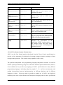
system group is mib-2 1 or 1.3.6.1.2.1.1, and so on. Figure shows the MIB-II subtree of the
mgmt branch.
Figure 1 H: MIB II tree
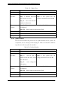
Table briefly describes each of the management groups defined in MIB-II.
Table 1.2.8.1 MIB II
Sub Tree Name
OID
Description
System
1.3.6.1.2.1.1
Defines a list of object that pertain to
system operation, such as the system
uptime, system contact and system
name.
Interface
1.3.6.1.2.1.2
Keeps track of the status of each
interface on a managed entity. The
interface group
monitors which
interfaces are up or down and tracks
such things as octets sent and received,
errors and discards, etc
1.3.6.1.2.1.3
The address translation (at) group is
deprecated and is provided only for
At (Address Translation)
Federal Urdu University
Page - 19
NET WORK ASSE T S MONIT ORIN G
AN D
SECURITY
USIN G
SNM P
background compatibility.
1.3.6.1.2.1.4
Keeps track of many aspects of IP,
including IP routing.
Icmp (Internet Control 1.3.6.1.2.1.5
Tracks things such as ICMP errors,
discards, etc.
Ip (Internet Protocol)
Management Protocol)
1.3.6.1.2.1.6
Tracks, among other things, the state of
the TCP connection.
Udp (User Datagram 1.3.6.1.2.1.7
Tracks UDP statistics, datagrams in and
out, etc.
Tcp
(transmission
control Protocol)
Protocol)
Egp (Exterior Gateway 1.3.6.1.2.1.8
Protocol)
Tracks various statistics about EGP and
keeps an EGP neighbor table.
Transmission
1.3.6.1.2.1.10
There are currently no objects defined
for this group, but other media-specific
MIBs are defined using this subtree.
Snmp
1.3.6.1.2.1.11
Measures the performance of the
underlying SNMP implementation on
the managed entity and tracks things
such as the number of SNMP packers
send and received.
1.2.9 ASN.1 (Abstract Syntax Notation One)
ASN.1 was the first formal notation (developed from the Xerox Courier specification) to
provide a clear separation of the high-level message content from the encodings of those
messages during transfer. This remains a major plank of ASN.1 today.
The platform-independent and (programming) language-independent notation is called an
abstract syntax specification, giving rise to the name Abstract Syntax Notation One (ASN.1).
It has enabled tools to provide easy mappings of ASN.1 specifications into many different
programming languages, including today the popular C, C++ and Java environments, and
making interworking between implementations on different platforms and in different
languages a reality. It has also made it possible to embed use of ASN.1 into high-level
modeling tools such as Specification and Description Language and test suite specification
Federal Urdu University
Page - 20
NET WORK ASSE T S MONIT ORIN G
AN D
SECURITY
USIN G
SNM P
languages such as Tree and Tabular Combined Notation (The linkage between SDL and
ASN.1 and between TTCN and ASN.1 has proved a very powerful mechanism for full
protocol specification using the range of ITU-T languages.)
Like ASN.1, both SDL and TTCN are still changing and expanding today. This is beyond the
scope of this paper, but is partly addressed by other papers in this issue8.
The separation of the high-level definition of message content (the abstract syntax of the
messages) from the specification of the actual bits to be used to encode different values of the
content was called the transfer syntax of the messages. This specification was typically done
by application-independent encoding rules that could be applied to any ASN.1 specification.
Whilst the abstract syntax concept made the mapping to programming language data
structures possible, the concept of encoding rules enabled application-independent
encode/decode libraries to be provided by tool vendors, making rapid and largely error-free
implementations of the encoding aspects of a protocol to be easily produced9.
Federal Urdu University
Page - 21
NET WORK ASSE T S MONIT ORIN G
AN D
SECURITY
USIN G
SNM P
Chapter 2
Project Planning & Management
2.1 Team Organization
Team will be Democratic Decentralized (DD). Team is decided on the basis of the factors
given below:
1. The difficulty of the problem:
Because decentralized teams generate more and better solutions than individuals
therefore such teams have a greater portability of success when working on difficult
problems.
2. The time that the team will stay together: (Team lifetime)
The length of time that the team will live together affects team morale. It has been
found that DD team structures result in high morale and job satisfaction and therefore
good for teams that will be live together for a long time.
3. The degree to which the problem can be modularized:
The problem is low modularity therefore DD team structure is best applied because of
higher volume of communication needed.
4. The degree of sociability (communication) required for the project:
DD required more time to complete a project and at the same time are best when high
sociability is required.
5. The required quality and reliability of the system to be built:
Because DD required more time to complete a project so it easily achieves quality and
reliability in system.
Federal Urdu University
Page –22
NET WORK ASSE T S MONIT ORIN G
AN D
SECURITY
USIN G
SNM P
6. The rigidity of the delivery data:
It is obvious that in DD the time is enough to deliver the project (software) in specific
time.
2.2 Resources
The following resources are used in the project.
Arif Saulat
(AS)
Ali Hanzala Khan
(AHK)
2.3 Team Structure
Team structure is depicted in the following figure (see figure 2A), which is showing how the
communication is being done in various phases of the project development. Both the team
members are equally involved in all phases of the project which results in implementing each
member’s skills and ideas in its respective area.
AS+A
HK
AS+A
HK
Design
Analysis
AS+A
HK
Implementation
AS+A
HK
Testing
Figure 2 A. Team Structure Diagram
Federal Urdu University
Page –23
NET WORK ASSE T S MONIT ORIN G
AN D
SECURITY
USIN G
SNM P
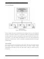
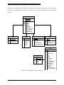
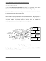
2.4 Network Diagram
Figure 2 B Network Diagram
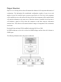
The above figure shows basic system architecture, here manager is the server side component
and agent is client side component of our application, MIB is the management information
base that contains the routine by following this routine agent populates the desired fields.
User Interface is the main interface that displayed on server side, Network management
application is backend routine, which is responsible for gathering information from agents
and data storage.
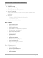
2.5 List of Task
Project development has been divided into 4 major phases. These have been further divided
into subtasks, which on completion mark the end of the phase. Analysis, design,
implementation and testing are those four major phases, which are essential in project
development.
Federal Urdu University
Page –24
NET WORK ASSE T S MONIT ORIN G
AN D
SECURITY
USIN G
SNM P
Phase-I (Analysis)
Establish list of tasks
Specify scope and feasibility
understand problem and outline requirements
How to do? /what to do?
Analyze problem, limitation, constraints in current systems and definite detail
Requirement
Plan project
1. prepare a schedule for design and implementation
2. decide process model
Research technical criteria and options
Phase -II (Design)
Design preliminary report
Design prototype screen
Design feasibility analysis
Decide HD(Hardware)/SF(Software) requirements
Develop prototype model/Approval
Design methods and procedures
Resource allocation
Algorithms design
Design flow chats
DFD(Data Flow Diagram)
ERD (Entity Relationship Diagram)
Design intermediate report
Design computer program specification
Phase -III (Implementation)
Plan for Programming
Write and computer program test
Design installation guide & user manual
Design presentation
Federal Urdu University
Page –25
NET WORK ASSE T S MONIT ORIN G
AN D
SECURITY
USIN G
SNM P
Install files and database
Phase - IV (Testing)
Test all features separately.
2.6 Project Planning:
The following steps are followed in planning for the completion of the project on the basis of
time allotted and resources available.
STEP-1:
Find the total time available for project completion:
Project Duration (PD) = 9 months
(Total number of months assigned by the supervisor.)
Total Number of Weeks (TNW) In Project Duration (Pd) = 38 weeks
Total Number of Days (TND) In Project Duration (Pd)
= 266 days
STEP-2:
Find the total number of days with each team member out of the time available:
Total Number of Days (TND)
Total Number of Holidays (TNH)
= 266 Days
= 80 Days
AWD Actual Working Days
AWD = TND – TNH Days
=
N
186 Days
= 186
No. of team members = m =2
N/m
= 186/2 = 93 (each members working day)
Federal Urdu University
Page –26
NET WORK ASSE T S MONIT ORIN G
AN D
SECURITY
USIN G
SNM P
Chapter 3
Aims and objectives
Network Assets Monitoring and Security using SNMP targets big organizations where
number of workstation is very large and network assets security is major issue. This software
will monitor the hardware whenever the configuration of hardware changes it will give alert
to administrator. The software is divided into two major modules
1) Monitoring
If configuration of any hardware changes than this system will detect these changes
automatically, question arises how? The answer is whenever the hardware is plugged
first time this system collects all hardware related information from that machine and
stored it in database. Whenever the hardware information changes this software scans
that hardware in normal routine and collect the desired data then it compares that data
with data that is stored in database if conflict arises than this is the indication of
problem in hardware configuration and if this changes is in the knowledge of
administrator then he may proceed for updating.
2) Inventory Management
If new hardware comes in organization then it should registered in inventory.
Nowadays inventory management is also very big issue we also solve this problem by
introducing the feature of auto registry in our software, now you only have to plugged
the network cable then this system will automatically registered the hardware in
database.
If the location or contact person of workstation changed then administrator can update
its description or contact person from server.
Federal Urdu University
Page - 27
NET WORK ASSE T S MONIT ORIN G
AN D
SECURITY
USIN G
SNM P
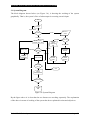
3.1 System Diagram
The block diagram shown below (see Figure 3A), is showing the working of the system
graphically. That is, the system’s flow of what output is occurring on each input.
Start
Login
Login Failed
If Admin
Scan or
View
If User
If Admin
ViewDB
Scan / View /
Create user / exit
Make user createUser
ScanNodes
Scan
Respective
Nodes
ViewDB
Check
options
scan
Assign
privileges
Scan the
desire
data from
DB
If Scan
If admin
Display
Scand
Data
Scan Nodes
Display
Scand
Nodes
exit
If Changes
occur
no
exit
Takes
Authentication
If Authenticate
yes
Update
DB
Figure 3A System Diagram
By the figure above it is clear that the two features are working separately. The explanation
of the above in terms of working of the system has been explained in aims and objectives.
Federal Urdu University
Page - 28
NET WORK ASSE T S MONIT ORIN G
AN D
SECURITY
USIN G
SNM P
3.2 Scope of Project
The scope of this project is the configuration and asset management of networked devices is
very vast where network assets security is basic need. This software can use in any
organization where number of workstation is very large. If number of workstation is large
then there should be some system that maintained the inventory of hardware. Monitoring
involve workstation monitoring, these workstation can be PC (personal Computer), switch or
some network enable heavy or light machinery of industry. This software will get information
of all hardware which have IP address and have SNMP service enabled for e.g. if you are
designing industrialist and you have to know how much design have been made from last two
days then you don’t have to go at your plant for counter reading you may just sit on server
and see the counter reading there. This software has various applications in similar fields.
We briefly tested our software on PNSC (Pakistan National Shipping Corporation) network,
which comprise of 300 workstations. This proved the utility of our software.
3.3 Project Overview
Table 1 PROJECT OVERVIEW
Network Assets Monitoring and Security
Project Title
Using
SNMP(Simple
Network
Management Protocol)
Team Organization
Democratic Decentralized (DD)
Programming Environment
Microsoft Windows XP/2000
Programming Methodology
Object Oriented Approach
Project Management Techniques
GANTT Chart
Programming Language
Front End
Visual Basic .Net
Back End
SQL Server 2000
CASE Tools/Supporting Tools
MS Visio, ERWIN
Software Process Model
Spiral Model
Federal Urdu University
Page - 29
NET WORK ASSE T S MONIT ORIN G
AN D
SECURITY
USIN G
SNM P
Chapter 4
Analysis & Design
4.1 Data Collection
For data collection, we downloaded and installed various network inventory softwares. The
major data collection is done by RFC 1213 and RFC 1257, which was referred by our
supervisor Mr. Mohiuddin, and as far as software flow and data presentation are concerned
we take full advantage of our senior faculty member Mr. Iqbal who enlightened us with his
views and gave us ideas and showed great interest in our project. He gives us introduction of
monitoring software, which monitors network traffic namely “SNMPc”, from which we get
knowledge about all components of network. Our supervisor Mr. Mohiuddin gave whole
project requirements.
Besides this, we visited various websites relevant to our project for reference (see Reference
section).
4.2 External Interface Requirements
The External Interface Requirements for this project is one or two workstation as a server and
access of organization network. The workstation at which server component is install and all
components that will be monitored by this application should be SNMP enabled.
4.3 Use Case Model
A Use Case is a procedural definition of functional requirements written in prose. It defines a
way in which a computer might be used by a user. It is made up largely of interactions across
the system boundary which defines an outside-in black box view of what the system will do
from a user's perspective. Use cases were defined by Ivar Jacobson in 1992 and have since
become an integral part of UML. Use cases are easy to understand for non-technical users but
hard to write properly. They can also be used for modeling business processes.
4.4 System level use-case diagram
The functional requirements of a computer system can be shown on a set of use case
diagrams which summaries all the system will do. It shows what use cases are used by what
Federal Urdu University
Page - 30
NET WORK ASSE T S MONIT ORIN G
AN D
SECURITY
USIN G
SNM P
external user roles and all systems and users with whom the system will interact. As such it
graphically defines the functional boundary of the system
The figure below (Figure 4 A) is a system level use case, showing that administrator and user
are two
Actors of the system, both have different privileges.
View All DB
Scan Network &
Update DB
Make User
Administrator
Change W/s Profile
View Respective DB
Scan Respective
Network
User
Figure 4 A Use Case Model
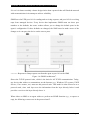
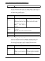
4.5 Use Cases
The system can be broken down into six separate use cases are as follows.
4.5.1 Use Case: view all Database
This use case describes the process of viewing all Database of the system. On
completion, success message will be displayed. Table 4.5.1 describes different
steps that are taken to view all database.
Table 4.5.1: View Report
Use Case Name
Federal Urdu University
View Reports
Page - 31
NET WORK ASSE T S MONIT ORIN G
SECURITY
AN D
Actor(s)
Administrator
Typical
Course Actor Action
USIN G
SNM P
System Response
of Events
Step 1:
actors want to view Step 2: System generates and
database first he has to select
displays all the details
criteria and view Database and
press OK button
Pre-Condition
None
Post-Condition
Display all the details of the particular Database
Assumptions
None at this time.
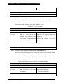
4.5.2 Use Case: Scan Network and Update Database
This use case describes the process of Scanning Network and Update Database
of the system. On completion, success message will be displayed. Table 4.5.2
describes different steps that are taken to Scan Network and Update Database
Table 4.5.2: Scan Network and Update database
Use Case Name
Scan Network and Update database
Actor(s)
Administrator
Typical
Course Actor Action
of Events
Step 1:
System Response
Retrieval of live Step 2: Start Manager
data in database
Scan all workstations
If scan data has conflict with data
in database
Then approval of administrator
required
If admin approve then update
database
Pre-Condition
Data Already Exit compare with this
Post-Condition
Display all the details of the particular Database
Assumptions
None at this time.
4.5.3 Use Case: Make User
This use case describes the process of the add User of the system. On
completion, success message will be displayed. Table 4.5.3 describes different
steps that are taken to add User.
Federal Urdu University
Page - 32
NET WORK ASSE T S MONIT ORIN G
AN D
SECURITY
USIN G
SNM P
Table 4.5.3: Make User
Use Case Name
Make User
Actor(s)
Administrator
Typical
Course Actor Action
of Events
System Response
Step 1: initiated when the Step 3: The system save the
actor create new User.
Step 2:
member information into the DB.
Actor enter the new
member information.
Alternate
Step 3A: If there is an error in the entries of the field, error message
Courses
is displayed.
Step 3B: Cursor comes on the incorrect field.
Pre-Condition
Data does not already exist.
Post-Condition
Data saved into the DB.
Assumptions
None at this time.
4.5.4 Update Member
This use case describes the process of the update member of the system. On
completion, success message will be displayed. Table 4.5.4 describes different
steps that are taken to update the member.
Table 4.5.4: Update Member
Use Case Name
Update Member
Actor(s)
Administrator
Typical
Course Actor Action
of Events
Step 1:
System Response
This use case is Step 3: The system save the
initiated when the actor selects change information into the DB.
the edit button.
Step 2:
Actor change the
information
Alternate
Step 3A: If there is an error in the entries of the field, error message
Courses
is displayed.
Step 3B: Cursor comes on the incorrect field.
Pre-Condition
Data already exists.
Post-Condition
Data is saved into the DB.
Federal Urdu University
Page - 33
NET WORK ASSE T S MONIT ORIN G
Assumptions
4.5.5
AN D
SECURITY
USIN G
SNM P
None at this time.
Delete Member
This use case describes the process of the delete member of the system. On
completion, success message will be displayed. Table 4.5.5 describes different
steps that are taken to delete member.
Table 4.5.5: Delete Member
Use Case Name
Delete Member
Actor(s)
Administrator
Typical
Course Actor Action
of Events
Step 1:
System Response
This use case is Step 3: The system save the
initiated when the actor selects change password into the DB.
the change password option.
Step 2:
Actor change the
password.
Alternate
Step 3A: If there is an error in the entries of the field, error message
Courses
is displayed.
Step 3B: Cursor comes on the incorrect field.
Pre-Condition
Data already exist.
Post-Condition
Data is saved into the DB.
Assumptions
None at this time.
4.5.6
Use Case: Change workstation profile
This use case describes the process of changing workstation profile of the
system. On completion, success message will be displayed. Table 4.5.6
describes different steps that are taken to changing workstation profile..
Table 4.5.6: Change Workstation Profile
Use Case Name
Change Workstation Profile
Actor(s)
Administrator
Typical
Course Actor Action
of Events
Step 1:
System Response
actors want to Step 2: Scan agent from Manager
change the user profile like View info of agent from manager
sysName etc.
Federal Urdu University
Change profile of
Page - 34
NET WORK ASSE T S MONIT ORIN G
AN D
SECURITY
USIN G
SNM P
workstation/agent.
Pre-Condition
You don’t have enough rights to change it
Post-Condition
Profile change successfully
Assumptions
None at this time.
4.5.7
Use Case: View Database
This use case describes the process of viewing database of user of the system.
On completion, success message will be displayed. Table 4.5.7 describes
different steps that are taken to viewing database of user.
Table 4.5.7: View Database
Use Case Name
View Database
Actor(s)
User
Typical
Course Actor Action
of Events
Step 1:
System Response
actors want to view Step 2: View respective data from
database first he has to select Database
criteria and view Database and Select
press OK button
the
criteria
view
Database
Pre-Condition
You don’t have enough rights to change it.
Post-Condition
Display all the details of the particular Database
Assumptions
None at this time.
4.5.8
then
Use Case: Scan respective Network and Update Database
This use case describes the process of scanning respective network and update
Database according to the privileges of user of the system. On completion,
success message will be displayed. Table 4.5.8 describes different steps that
are taken to viewing database of user.
Table 4.5.8: Scan respective Network and Update Database
Use Case Name
Scan respective Network and Update Database
Actor(s)
User
Typical
Course Actor Action
of Events
Step 1: Retrieval of live data Step 2: Start Manager
in database.
Pre-Condition
Federal Urdu University
System Response
Scan all workstations
You don’t have enough rights to change it.
Page - 35
NET WORK ASSE T S MONIT ORIN G
AN D
SECURITY
Post-Condition
Display Live Data.
Assumptions
None at this time.
USIN G
SNM P
4.6 User Documentation
The documentation provided to the user along with the software includes:
1. User Manual (see Appendix B)
The Format of the documentation is MS Word based.
4.7 Algorithm
1 input user name and password
2 if admin then
2.1 input options scan network or view database or create user
2.1.1 If scan network
2.1.1.1 Then scans the network and gather information
2.1.1.2 Compare gathers information with information in database
2.1.1.3 If conflict occur
2.1.1.3.1 Then ask for approval from administrator
2.1.1.3.1.1 If approval given then update database.
2.1.1.3.1.2 If not then go step 2.1.1
2.1.1.4 if conflict not occur
2.1.1.4.1 Display the scan output
if view database then display all database records
if create user
make user and assign privileges and go to 2.1
3 if user then
3.1 input option scan network or view database
3.1.1 If scan network
3.1.1.1 Then scans the respective network and gather information
According to the rights.
3.1.1.1.1 If rights then Display the scan output
3.1.1.2 If not then go to 3.1
3.1.2 If view database then display all database records.
Federal Urdu University
Page - 36
NET WORK ASSE T S MONIT ORIN G
AN D
SECURITY
USIN G
SNM P
4.8 Data Flow diagram
The Data Flow Diagram – DFD shows the flow of data or information. It can be portioned
into single processes or functions. Data flow diagram can be grouped together or decomposed
into multiple processes.
The DFD is an excellent communication tool for analyst to model processes and functional
requirements. One of the primary tools of the structured analysis efforts of the 1970’s it was
developed and enhanced by the likes of Yourdon, McMenamin, Palmer, Gane and Sarson. It
is still considered one of the best modeling techniques for eliciting and representing the
processing requirements of a system.
We have used DFD to show the relationships between the major components in the system.
Network assets monitoring and Inventory Management are the two processes being carried
out in the system the relationship are shown below (Figure 2 B)
If Administrator
Take
Authentication
of
Administrator
Admin
If Not Approved
If Approved
Update
Scan Network
login
Create
User
If Conflict
If Scan
Scan / View
Compare
Scand data
with data in
Database
Set
Parameter
Database
If View
If User
User
View Data
Base
Figure 4 B: Data Flow Diagram
4.9 Entity Relationship Diagram (ERD):
Data models are tools used in analysis to describe the data requirements and assumptions in
the system from a top-down perspective. There are 3 basic elements in ER models:
Federal Urdu University
Page - 37
NET WORK ASSE T S MONIT ORIN G
AN D
SECURITY
USIN G
SNM P
Entities are the things about which seek information. Attributes are the data we collect about
the entities. Relationships provide the structure need to draw information from multiple
entities.
MachineInfo
PK
PK
IPAddress
MachineID
FK4
FK1
FK3
FK2
SERID
OSID
CardID
HDDID
BIOSVendor
BIOSDate
TotalInstallMemory
MemorySpeed
TotalPCISlots
TotalEISASlots
Services
PK
SERVICEID
ServicesInstalled
ServicesRunning
HDD
Cards
PK
CardID
CardType
Brand
Driver
Speed
Slot
PK
HDDID
OS
PK
HDDType
Size
TotalNoofPartition
TotalAvailableSpace
OSID
OSVersion
OSName
OSInstallationDate
Privileges
PK
Admin
PK
UserName
FK1
Password
Role
PriID
PriID
BIOS
MemoryCard
HDD
Slots
Memory
Cards
BIOSVendor
BIOSDate
TotalInstallMemory
MemorySpeed
TotalPCISlots
TotalEISASlots
HDDType
HDDSize
TotalNoofPartition
TotalAvailableSpace
Figure 4 C: Entity Relationship Diagram
Federal Urdu University
Page - 38
NET WORK ASSE T S MONIT ORIN G
AN D
SECURITY
USIN G
SNM P
4.10 Software Process Model
We have used Component Assembly Model (see figure 7) as our Software Process Model.
The reason behind this is that it follows Object Oriented Software Engineering.
We will make different components according to our need and these components will further
be reused if required in any other relevant system.
Object Oriented Analysis is quite different from conventional analysis. There are number of
methods which can be followed in this respect. Our selected method is “The COAD and
YOURDON Method”. Its modeling notation is relatively simple and guidelines for
developing the analysis model are straightforward and uncomplicated.
Identify
candidate
component
Risk
Analysis
Planning
Construct
nth iteration
Customer
Communication
of
system
Put new
comps in
library
Engineering
Customer
Evaluation
Lookup
component
in library
Extract
component if
available
Build
component if
unavailable
Construction
& Release
Figure 4D. Component Assembly
Model Diagram
For Object Oriented Design, we have used the same method i.e. COAD & YOURDON
Method. OOD includes the following steps:
Federal Urdu University
Page - 39
NET WORK ASSE T S MONIT ORIN G
AN D
SECURITY
USIN G
SNM P
Problem Domain Components
o We have grouped all domain classes.
o We have developed an interface with Data Management Components.
o Reviewed design to make some improvement.
Human Interaction Components
o Task scenarios will be developed.
o Hierarchy of user commands and GUIs.
o Integration of GUIs.
Federal Urdu University
Page - 40
NET WORK ASSE T S MONIT ORIN G
AN D
SECURITY
USIN G
SNM P
Chapter 5
Feasibility Analysis
It describes the technical, operational and economical feasibility of the system. The costing is
done using two different methods, which are function point method and COCOMO
5.1 Technical Feasibility
The system will be technically feasible, as no highly sophisticated hardware will be
needed
5.1.1 Feasible / Alternate Solution
Technical feasibility in terms of minimum hardware and software requirements
is listed in the table below. Visual Basic.Net is easier and faster to use and above
all is one of the most widely used programming language in the market today.
MS Visio has been used for scheduling such as Network diagram (see
Appendices), provides an easy and quick development.
Table 2 Feasibility Report
HARDWARE REQUIREMENTS
MACHINE (SYSTEM)
P-IV FULLY LOADED
STORAGE MEDIA
HARD DISK 40 GB
BACK UP DEVICE
ONE HARD DISK (10-20 GB)
NETWORK TOPOLOGY
NONE
OTHER REQUIREMENTS FOR NETWORKS
NONE
OTHER DEVICES/EXTERNAL INTERFACE
DOT MATRIX PRINTER/INKJET
SOFTWARE REQUIREMENTS
WINDOWS XP/200 WITH SNMP SERVICE ENABLED
APPLICATION TOOLS
BACK-END
SQL SERVER 2000
FRONT-END
VISUAL BASIC 6.0, VISUAL BASIC .NET
SUPPORTING TOOLS
Federal Urdu University
MICROSOFT VISIO, ERWIN
Page -41
NET WORK ASSE T S MONIT ORIN G
AN D
SECURITY
USIN G
SNM P
5.2 Operational Feasibility
The Operation Feasibility means that a lay man should easily understand it. Our software has
a user friendly GUI (Graphical User Interface) environment. Along with this, HELP (see
Appendix B) would also be maintained which would guide the user, and it is a menudesignated project.
SNMP Manager
Figure 5 A SNMP Manager
Federal Urdu University
Page -42
NET WORK ASSE T S MONIT ORIN G
AN D
SECURITY
USIN G
SNM P
SNMP Agent
Figure 5 B SNMP Agent
SNMP Manager Explorer
Figure 5 C SNMP Manager Explorer
Federal Urdu University
Page -43
NET WORK ASSE T S MONIT ORIN G
AN D
SECURITY
USIN G
SNM P
Trap Catcher
Figure 5 D SNMP Trap Catcher
Federal Urdu University
Page -44
NET WORK ASSE T S MONIT ORIN G
AN D
SECURITY
USIN G
SNM P
Chapter 6
Implementation
This chapter does not include complete listing but description of key parts, how the system
has been divided into various phases and then coded.
6.1 Tasks break up
This application may be treated as stand-alone application there are four different
module whish may further divided in to following sub modules (see figure 6A).
1) SNMP Manager
2) SNMP Agent
3) SNMP Explorer
4) SNMP Trap Catcher
Network Assets Monitoring and Security using SNMP
Snmp Manager
Start manager and
scan network
Snmp Explorer
Snmp Agent
Snmp Trap Catcher
Start Agent
View agent system
information
Send Trap
Update Agent's
Information
Set Request History
Get Table
View Trap Log
Figure 6 A: Different Modules of Implementation
Federal Urdu University
Page - 45
NET WORK ASSE T S MONIT ORIN G
AN D
SECURITY
USIN G
SNM P
6.1.1 SNMP Manager
This module will run on server and do main scanning of all SNMP enabled
devices attached on network.
The major functions of SNMP Manager are as follows.
1) Start Manager and Scan Network
Make connection of this module with network by using UDP port 162. After
establishing the connection, it will discover all the agents which is connected to
network at that moment.
If cmdStart.Text = "Start Manager" Then
Try
Manager1.Open (162)
UpdateInterface (True)
DiscoverAgents ()
Catch ex As Exception
If ErrorNumber (ex) = 10048 Then
ShowError ("Port 162 is already in use")
Else
ShowError (ex.Message)
End If
End Try
Else 'If open, close manager
Manager1.Close ()
UpdateInterface (False)
Federal Urdu University
Page - 46
NET WORK ASSE T S MONIT ORIN G
AN D
SECURITY
USIN G
SNM P
Figure 6.1.1: Snmp Manager
2) View Agent System Information
If you want to see the system information of particular agent you only have to
select the agent from the agent discovered list. See Figure 5.1.1 for agent
system information.
If lstAgents.Items.Count > 0 Then
lstAgents.Enabled = True
lblStatus.Text = lblStatus.Text + "added” +
lstAgents.Items.Count.ToString () + “agents." + vbCrLf
lblStatus.Text = lblStatus.Text + "Select an agent to get
its system info."
Else
lblStatus.Text = lblStatus.Text + "no agents found."
End If
Federal Urdu University
Page - 47
NET WORK ASSE T S MONIT ORIN G
AN D
SECURITY
USIN G
SNM P
3) Update Information of Agent
Now if you want to update information of any agent, just select the desire
agent from the agents list then click on the field witch you want to change.
When you click the field the new form will load, in which you can edit
information.
lblStatus.Text = "Double-click on a variable to set its value."
cmdTable.Enabled = True
DoGetRequest (lstAgents.SelectedItem)
Figure 6.1.3: Snmp Manager
4) View Trap log
Click on the Trap log button to view trap log
Dim frm As New frmTrapLog ()
frm.DisplayLog (trapLog)
frm.ShowDialog ()
Federal Urdu University
Page - 48
NET WORK ASSE T S MONIT ORIN G
AN D
SECURITY
USIN G
SNM P
5) Get Table
If you want to know that your manager made how many update on which
agents then you click GET Table
Manager1.Message.Reset ()
Manager1.AgentPort = 161
Manager1.AgentName = lstAgents.SelectedItem
Manager1.Message.Type = TypeConstants.snmpGetNext1
Manager1.Message.Variables.Add (v)
6.1.2 SNMP Agent
This part will install on client or agent side for viewing agent’s own
description and its second main function is to send traps to the server or
broadcast it.
The major functions of SNMP Manager are as follows.
1) Start Agent
As you try to start agent if UDP port 162 is no busy agent will start, after it
will gather all information of respective machine and display it
Agent1.Open 161
SetStatus "Open on port” & Agent1.LocalPort, True
startTime = GetTickCount 'for sysUpTime
'Open port for sending traps
On Error GoTo TrapError
cmdTrap.Enabled = True
txtDescr.Text = Agent1.Mib.Variables("sysDescr").value
txtObjectID.Text = Agent1.Mib.Variables("sysObjectID").value
txtContact.Text = Agent1.Mib.Variables("sysContact").value
txtName.Text = Agent1.Mib.Variables("sysName").value
txtLocation.Text = Agent1.Mib.Variables("sysLocation").value
Federal Urdu University
Page - 49
NET WORK ASSE T S MONIT ORIN G
AN D
SECURITY
USIN G
SNM P
Figure 6.1.2: Snmp Agent
2) Send Trap
You may fire traps to any of the desire workstation just by clicking send
button on main agent screen. See Figure 5.2 for sending trap.
Agent2.Message.Reset
Agent2.Message.Type = snmpTrap1
Agent2.Message.GenericTrap = snmpWarmStart
Agent2.Message.Enterprise = txtObjectID.Text
'Add Variable to Trap
AddVariable Agent2.Message.Variables,
Mib.Variables.GetOIDFromName("sysUpTime"), snmpTimeTicks,
GetUpTime
'Set destination and Send
Agent2.TrapManagers.Clear
Federal Urdu University
Page - 50
NET WORK ASSE T S MONIT ORIN G
AN D
SECURITY
USIN G
SNM P
Agent2.TrapManagers.Add txtDestination.Text
Agent2.Send
cmdTrap.Enabled = True
3) Set Request History
If you want to view the history of changes made by server then you should
see set table history table
txtDescr.Text = GetRegSetting(gKey, "sysDescr", "Dart Sample
Agent")
txtObjectID.Text = GetRegSetting(gKey, "sysObjectID",
"1.3.6.1.4.1.52222")
txtContact.Text = GetRegSetting(gKey, "sysContact", "Fiona
Quartwhistle")
txtName.Text = GetRegSetting(gKey, "sysName", "Steve")
txtLocation.Text = GetRegSetting(gKey, "sysLocation", "A
little bit above the floor and far below the ceiling")
6.1.3
SNMP Explorer
It scans all the SNMP enable devices on the network and display it its
description in tree format. It also catches the trap messages generated by any
agent and display also its information in tree manner.
AddProp Node, "sysDescr", "1.3.6.1.2.1.1.1.0"
AddProp Node, "sysObjectId", "1.3.6.1.2.1.1.2.0"
AddProp Node, "sysUpTime", "1.3.6.1.2.1.1.3.0"
AddProp Node, "sysContact", "1.3.6.1.2.1.1.4.0"
AddProp Node, "sysLocation", "1.3.6.1.2.1.1.6.0"
AddProp Node, "sysName", "1.3.6.1.2.1.1.5.0"
AddProp Node, "sysServices", "1.3.6.1.2.1.1.7.0"
Federal Urdu University
Page - 51
NET WORK ASSE T S MONIT ORIN G
AN D
SECURITY
USIN G
SNM P
Figure 6.1.3: Snmp Explorer
6.1.4 Trap Catcher
It catches the traps, which are fired by an agent and display all information
about that trap. It uses UDP port 162 for communication with agent.
Manager1.Open (Convert.ToInt32 (txtPort.Text),
txtAddress.Text)
UpdateStatus (True)
Dim
entry
As
String
=
"Trap
received
from
host”
+
Manager1.AgentName
logFile.Write(System.Text.Encoding.Default.GetBytes(msg),0,
msg.Length)
Federal Urdu University
Page - 52
NET WORK ASSE T S MONIT ORIN G
AN D
SECURITY
USIN G
SNM P
Figure 6.1.4: Snmp Trap Catcher
Federal Urdu University
Page - 53
NET WORK ASSE T S MONIT ORIN G
AN D
SECURITY
USIN G
SNM P
Chapter 7
Testing
This chapter includes the test cases developed for this system. Testing is that phase which
explains the scope, approach, resources and schedule of the quality assurance and testing
activities. Defines items/features to be tested, testing tasks to be performed, personnel
responsible for each task and risks associated with the test plan.
7.1 Test cases
Test case is a document that describes an input, an action, or an event and an expected
response, to determine if a feature of an application is working correctly.
Testing is an extremely important phase and if not conducted properly can result into a
bad product, not meeting requirements. The system was thoroughly tested, especially
focusing the GUIs and determining the behavior. Following are test cases developed for
this system:
7.1.1
Test Case 1- Login Screen
The following test case is for testing Login Screen. It takes the username and
password as the input. The results are being verified and given authentication
to the user or administrator according to their rights.
Table 3: Login Screen Test
Fields
Ok
Ok
Ok
Input
Expected Result
Some Field Still
Please enter correct user name
null
or password
Username
Please input correct password
User name and
password
Federal Urdu University
Login accept
Remarks
Fail
Fail
Pass
Page - 53
NET WORK ASSE T S MONIT ORIN G
AN D
SECURITY
USIN G
SNM P
7.1.2 Test Case 2- Snmp Explorer Screen
The following test case is for testing Snmp Explorer Screen. The input
parameters are displayed as the static manners. The resulting output is
discover SNMP enable agent on the network
Table 4 SNMP Explorer Screen Test
Fields
Discover Agent
Refresh
Input
Expected Result
Click discover
Discover SNMP enabled
agent
Devices
Click refresh
Click add
Add Machine
machine and
Discover new hardware
changes
Remarks
Pass
Pass
Add to the list of Snmp
Enable devices
give Accurate Ip
Pass
address
Click add
Add machine
No such hardware found
machine and
Fail
give 123 rather
than IP address
7.1.3 Test Case3-SNMP Manager Screen
The following test case is for testing Snmp Manager Screen. The input
parameters are displayed as the static manners. The output is discovering
Snmp enable agent on the network as well as its description, sysLocation etc.
Table 5 SNMP Manager Screen Test
Fields
Input
Start manager
Port already use
Start manager
Port closed
Refresh List
Close port first and then start
manager
Start manager open port 162
Click Refresh
Refresh Above list and
some field still
finding other Snmp Enabled
null
Add
Expected Result
Click add
Federal Urdu University
Remarks
Fail
Pass
Pass
Device
Add to the list of Snmp
Pass
Page - 54
NET WORK ASSE T S MONIT ORIN G
AN D
SECURITY
USIN G
SNM P
Enable devices
Click add and
Add
Cannot find Ip Address
type incorrect IP
Fail
address
Get Table
Get Table
Click Get Table
Request
if log created
Pass
Table
Click Get Table
Debugging request
if log not created
Click trap log
View trap log
Display log file to see set
Fail
Display trap log file
trap received
Pass
enabled
Double click to
sysLocation
New SysLocation field appear
change
to set field
Pass
sysLocation
sysName
sysDescription
Double click to
New SysName field appear to
change sysName
set field
Double click to
New SysDescription field
Change
appear to set field
Pass
Pass
sysDescription
7.1.4 Test Case4-Searching Screen
The following test case is for testing Searching Screen. The user would be
given different condition for searching such as IP address, SysLocation,
SysName etc. the desired fields are verified in database and display records in
list View.
Table 6 Searching Screen Test
Fields
Select Searching
Condition
Input
Field is empty
Select searching
condition (Ip
address) range is
Federal Urdu University
Expected Result
Retrieve all field from
database
Remarks
Pass
The Ip Address you specified
IP Address
doest not match please try
Fail
again
Page - 55
NET WORK ASSE T S MONIT ORIN G
AN D
SECURITY
USIN G
SNM P
not correctly
entered
Select Searching
Retrieve data related to Hard
condition(Hard
Hard Disk
Disk
Pass
Disk)
Select Searching
Retrieve all field Against the
Condition(Ip
IP Address
IP address from the database
Pass
Address)
Select Searching
Retrieve all field Against the
Condition(Hard
Hard Disk
Hard Disk from the database
Pass
Disk)
Select Condition
Please Specified Search
None
Condition
Fail
7.1.5 Test Case4-Agent Screen
The following test case is for testing Snmp Agent Screen. The input
parameters are displayed as the static manners. The output is showing new
SysLocation, sysName, SysContact etc. and maintains a set request table as
well as send trap to the Snmp Manager Screen.
Table 7: Agent Screen Test
Fields
Start agent
Input
Expected Result
Click Agent
Port 161 open
start
Click Agent
Start agent
Remarks
Pass
Port 161 in use
start already
Fail
open for trap
Send
Click Send
Federal Urdu University
Trap Sent to the Snmp
Manager
Pass
Page - 56
NET WORK ASSE T S MONIT ORIN G
AN D
SECURITY
USIN G
SNM P
7.2 Results
The test cases were designed in order to test the system’s working. Test cases are
designed for every user interface separately to check for the expected responses from the
system. This resulted in a system, if not 100% bug free but to a major extent, bugs were
removed. Retesting is a good practice and helps in identifying defects and their removal
from the system.
Federal Urdu University
Page - 57
NET WORK ASSE T S MONIT ORIN G
AN D
SECURITY
USIN G
SNM P
8 Conclusions
Development of Network Assets Monitoring and security using SNMP, gave us a chance to
follow software engineering completely and thoroughly. It started from analysis phase and
then projects planning, its management, implementation in a language we had never used
before, then thorough testing of the system by performing all the various tests in order to
achieve quality.
Network Assets Monitoring and Security is useful in two major areas, one is network assets
monitoring and other is inventory management. A lot can still be done in terms of
functionality and can be extended to heavy and light machinery management.
This software would provide a base for those who want to implement it in some other area /
field such as for some other industry. We believe that, who ever puts hands on this report
would like to enhance this project and develop more efficient algorithm for implementing
such solutions
It is hoped that such systems would help in automating our industry to the level that it is able
to come at par with the competitors in the field. At the same time would help in generating
quality and accurate products.
Federal Urdu University
Page - 58
NET WORK ASSE T S MONIT ORIN G
AN D
SECURITY
USIN G
SNM P
9 Future Works
We can do lot more things in the field of network assets security. The major enhancement we
can do is screen capturing of client’s workstation, if client have any problem he only have to
raise query the administrator will handle problem from server. The second enhancement
could be that we can set a camera at our work place if any workstation is not responding than
suddenly that camera take snap of infected region, and from that snap we can easily find the
prosecute. This application can also be applied in various heavy or light machinery of
industry. This software will get information of all hardware, which have IP address and have
SNMP service enabled. for e.g. if you are designing industrialist and you have to know how
much design have been made from last two days then you don’t have to go at your plant for
counter reading you may just sit on server and see the counter reading there, one more aspect
is that we can facilitate the manager by most of the things online manager will have to logon
from anywhere and see the desired data and made certain steps to overcome the problems.
This software has various applications in similar fields.
Federal Urdu University
Page - 59
NET WORK ASSE T S MONIT ORIN G
AN D
SECURITY
USIN G
SNM P
10 References
1) www.oreilly.com/catalog/esnmp/chapter
2) www.SNMP4tPC.com (SNMP for the Public Community)
3) www.Simple-Times.org- is an openly-available publication devoted to the promotion of the SNMP.
4) www.SimpleWeb.org, University of Twente - provides links and information on network
management.
5) www.SNMPBOY.msft.net (Microsoft Corporation) - Monitoring with MRTG on NT systems
6) www.SNMPInfo.com - is a consulting and software development company founded in
1997 by David T. Perkins.
7) www.mibDepot.com (Previously known as MibCentral.com) - mibDepot offers a new way to view
and search through a very large number of SNMP MIBs.
8) www.SLAC.stanford.edu/xorg/nmtf - Network Monitoring Tools - This is a list of tools used for
Network (both LAN and WAN) Monitoring tools and where to find out more about them. The audience
is mainly network administrators.
9) www.netmon.com Network Monitoring Tools and Tutorials - A detailed listing of tools to help any
sized network monitor their network. The focus is on low cost tools for Windows.
10) www.arnoc.com - NetManage Links Directory
11) www.chapo.co.il/articles/snmp Network Management Protocols - Written by Oren Chapo * August
1999
Federal Urdu University
Page - 60
NET WORK ASSE T S MONIT ORIN G
AN D
SECURITY
USIN G
SNM P
APPENDIX A
ASN:
(Abstract Syntax Notation) The OSI Language for describing abstract
syntax.
Authentication:
The process whereby a message is associated with a particular
originating entity
AE:
Authentication Entity (SNMPv1) that portion of an SNMP agent
responsible for verifying that an SNMP
Entity is a member of the community to which it claims to belong. This
portion of the agent is also responsible for encoding / decoding SNMP
Messages according to the authentication algorithm of a given
community.
Authorization:
The process whereby an access policy determines whether an entity is
allowed to perform an operation
BER:
(Basic Encoding Rules) The OSI language for describing transfer
syntax.
CCITT:
International Telegraph and Telephone Consultative Committee
CMIP:
Common Management Information Protocol the OSI protocol for
network Management
Community:
(SNMPv1) and administrative relationship between SNMP entities.
Community Name: (SNMPv1) an opaque string of octets identifying a community.
Connection:
Logical binding between two or more users of a service.
Datagram:
A self-contained unit of data transmitted independently of other
datagram.
Device:
A network element of some kind.
DNS:
Domain name system the application protocol offering naming service
in the internet suite of protocols.
Enterprise MIB:
A MIB module defined in the enterprise-specific portion of the internet
management space.
Flow Control:
the mechanism whereby a receiver informs a sender how much data it
is willing to accept.
IANA:
Internet assigned Numbers Authority.
Host:
an End System.
Federal Urdu University
A-I
NET WORK ASSE T S MONIT ORIN G
Internet Protocol:
AN D
SECURITY
USIN G
SNM P
the network protocol offering a connectionless-mode network service
in the Internet suite of protocols.
IP Address:
A 32-bit quantity used to represent a point of attachment in an Internet.
LAN:
Local Area Network any one of a number of technologies providing
high speed, low-latency transfer and being limited in geographic size.
Managed Node:
A device containing a network management agent implementation.
MIB:
(Management Information Base) a collection of object that can be
accessed via a network management protocol.
MIB view:
a collection of managed objects realized by an agent, which is visible
to a management application.
Manager:
an application residing on a network management station.
NMS:
(Network Management Station) an end-system responsible for
managing (a portion of) the network.
Network identifier: that portion of an IP Address corresponding to a network and an
internet.
Object Instance:
a particular instance of an object type.
Object Type:
an abstract definition of a managed object.
Physical layer:
that portion of an OSI-system responsible for the electromechanical
interface to the communications media.
Port number:
identifies an application-entity to a transport service in the internet
suite of protocols.
PDU:
a data object exchanged by protocol machines, usually containing both
protocol control information and user-data.
Prototype:
(management usage) the object type corresponding to an instance.
RFC:
(request for Comments) the document series describing the internet
suite of protocols and related experiments.
SNMP:
the application protocol offering network management service in the
internet suite of protocols.
SMI:
(Structure of Management Information) the rules used to define the
objects that can be accessed via network management protocol.
Subnet:
a physical network within an IP network.
Subnet mask:
a 32-bit quantity indicating which bits in an IP address identifies the
physical network.
Federal Urdu University
A-II
NET WORK ASSE T S MONIT ORIN G
Subnet number:
AN D
SECURITY
USIN G
SNM P
that portion of an IP host identifier, which identifies a particular
physical network within an IP network.
Subnetting:
the process of using IP Subnetting procedures.
UDP:
User Datagram Protocol the transport protocol offering a connection
less mode transport service in the internet suite of protocols.
Federal Urdu University
A-III
NET WORK ASSE T S MONIT ORIN G
AN D
SECURITY
USIN G
SNM P
APPENDIX B
Introduction:
Network Assets Monitoring and Security using SNMP targets big organizations where
number of workstation is very large and network assets security is major issue. This software
will monitor the hardware whenever the configuration of hardware changes it will give alert
to administrator. The software is divided into two major modules
1) Monitoring
If configuration of any hardware changes than this system will detect these
changes automatically, question arises how? The answer is whenever the
hardware is plugged first time this system collects all hardware related
information from that machine and stored it in database. Whenever the
hardware information changes this software scans that hardware in normal
routine and collect the desired data then it compares that data with data that is
stored in database if conflict arises than this is the indication of problem in
hardware configuration and if this changes is in the knowledge of
administrator then he may proceed for updating.
2) Inventory management
If new hardware comes in organization then it should registered in inventory.
Nowadays inventory management is also very big issue we also solve this
problem by introducing the feature of auto registry in our software, now you
only have to plugged the network cable then this system will automatically
registered the hardware in database.
If the location or contact person of workstation changed then administrator can
update its description or contact person from server.
B- I
NET WORK ASSE T S MONIT ORIN G
AN D
SECURITY
USIN G
SNM P
APPENDIX B
Once the user accesses the system the main screen below would be displayed.
Figure B-1 Splash Screen
A&A Manager:
This module will run on server and do main scanning of all SNMP enabled devices attached
on network. This is an stand alone module of project and don’t have any dependencies this
module can scan and edit information all SNMP enable devices attached on network with out
any help of client side application.
Figure B-2 SNMP Manager Screen
B- II
NET WORK ASSE T S MONIT ORIN G
AN D
SECURITY
USIN G
SNM P
Click Start Manager for connection establishment as shown in (Figure B-1)
Once connection is established, it will gather all the SNMP enabled workstation on the
network and display it in available Agent list. Then by clicking the desire agent, we can find
its system information as shown in (Figure B-2).
Figure B-2 A SNMP Manager Screen
If you want to change the desire Agent Information related to System Information just double
click the desired text field against the System Information and changed it as shown in (Figure
B-3)
B- III
NET WORK ASSE T S MONIT ORIN G
AN D
SECURITY
USIN G
SNM P
Figure B-2 B Set Value Screen
If you want to know what changes, you have made so far in which agent then you should
click Get Table as shown in (Figure B-3)
Figure B-3 Get Table
B- IV
NET WORK ASSE T S MONIT ORIN G
AN D
SECURITY
USIN G
SNM P
If you want detail of all Traps received so far at this manager then you should click View
Trap Log as shown in (figure B-5)
Figure B-4 View Trap
A&A SNMP Agent:
A&A SNMP Agent is use at client side but it is not facilitates SNMP Manager because
SNMP manager is its self independent application. Its major function is to maintain the
temporary record of set request made by manager and use for firing traps. In the beginning
for starting agent press Start Agent button as shown in (Figure B-5)
B- V
NET WORK ASSE T S MONIT ORIN G
AN D
SECURITY
USIN G
SNM P
Figure B-5 SNMP Agent Screen
If you want to view Set Request detail you can see in set request table and if you want to fire
trap you may press send button as shown in (Figure B-6)
Figure B-6 Overview Agents
B- VI
NET WORK ASSE T S MONIT ORIN G
AN D
SECURITY
USIN G
SNM P
Trap Catcher:
It manages all information regarding traps received so far for starting Trap Catcher press
Start button. It uses UDP Port 162 for receiving the Traps.
Figure B-7 Trap Catcher
You may see the received traps information in (Figure B-9)
Figure B-8 Trap Start and Catches Trap
B- VII
NET WORK ASSE T S MONIT ORIN G
AN D
SECURITY
USIN G
SNM P
SNMP Explorer:
It is use for scanning all SNMP enable devices attached to the network and it also keep
reference level information of traps receive on server. All information in SNMP Explorer
display is in tree format it uses UDP port 162 for communication.
You do not have to weary about SNMP Explorer working you just run this module and
exploring network as shown in (Figure B-10). This module is also stand alone application
and don’t have any sort of dependencies on client side application.
Figure B-9 SNMP Explorer
B- VIII
APPENDIX C
Resource Allocation
Below, is a list of, how resources have been allocated in all phases of the project that is the
participation of project members in each phase of system development.
Task
Recourse
Days
ANALYSIS
Establish list of tasks
A.A
6
Specify scope and feasibility
I.S
6
Understand problem and outline requirements
I.S
4
How to do? /what to do?
I.S
4
Analyze problem, limitation, constraints in current systems
and definite detail requirement
Plan project
1.
prepare a schedule for design and implementation
I.S
6
2.
decide process model
I.S
4
A.A
4
Design preliminary report
I.S
3
Design prototype screen
I.S
3
Design feasibility analysis
I.S
3
Decide Hardware/Software requirements
I.S
3
Develop prototype model/Approval
I.S, A.A
5
Design methods and procedures
I.S, A.A
16
Resource allocation
I.S, A.A
2
Algorithms design
I.S, A.A
5
Arrange meeting to finalized algorithms
I.S, A.A
5
Design flow chats
I.S, A.A
4
DFD (Data Flow Diagram)
I.S, A.A
4
ERD ( Entity Relationship Diagram)
I.S, A.A
5
Design intermediate report
I.S, A.A
5
Research technical criteria and options
DESIGN
C-I
IMPLEMENTATION
Plan For Programming
I.S, A.A
5
Write and computer program test
I.S, A.A
3
Design installation guide & user manual
I.S, A.A
2
Design presentation
I.S
2
Install files and database
I.S
5
I.S, A.A
20
TESTING
Test all features separately.
C-II
Appendix D
NETWORK MONITORING AND SECURITY USING SNMP
A& I Network Solution Providers
Group Name
Group Members
Imran Shabbir
Name
Contact info.
E-mail
Phone no.
Mobile no.
Field of Interest
Worked on
[email protected]
021-6648616
0304-2595955
Console Based/Web Applications/Network Programming
VB .Net, SQL Server 2000
NETWORK MONITORING AND SECURITY USING SNMP
A&I Network Solution Providers
Group Name
Group Members
M. Asif Ahmed Khan
Name
Contact info.
E-mail
Phone no.
Mobile no.
Field of Interest
Worked on
[email protected]
021-6691866
0321-2364024
Console Based/Web Applications/Network Programming
Visual Basic 6.0, VB .Net, SQL Server 2000
Project Overview
Objective is to develop software that will maintain the database of all component information of
workstations. The information like motherboard configuration, number of ports in use and
number of ports free, hard disk space, processor speed and so on. The Server side component
will be installed on server side and on the client side the client component will be installed which
will send the information to the main server. When the software is installed for the first time it
will broadcast a signal to all the client side computers to send their respective information
mention above. This software will monitor hardware changes of components of the workstation
in real time.
Developed Front-end using VB.Net and Back-end using SQL Server 2000
In SNMP architecture server side is referred as SNMP manager and the client side is known as
SNMP agent.
The following illustration shows the project architecture.