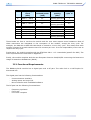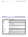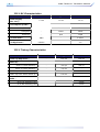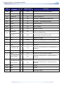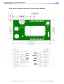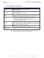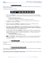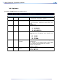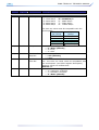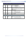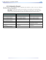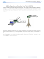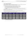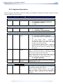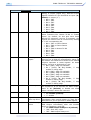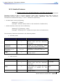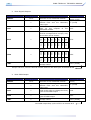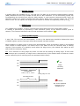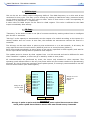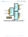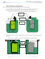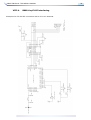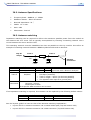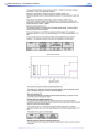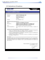
1
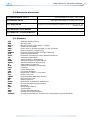
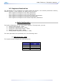
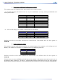
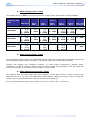
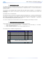
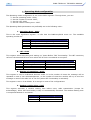
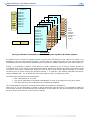
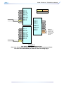
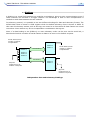
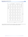
ISSUE: v1.4
UPDATE: December 2008
B868-TINYPLUS: TECHNICAL MANUAL
i
Proprietary Notice:
© Copyright Telit 2008
The information in this document is subject to change without notice.
Company or product names mentioned in this document may be trademarks or registered
trademarks of their respective companies.
All rights reserved. Neither the whole nor any part of the information contained in this
publication may be reproduced in any material form except with the written permission of
Telit.
This publication is intended only to assist the reader in the use of the product. Telit shall not
be liable for any loss or damage arising from the use of any information in this publication,
or any error or omission in such information, or any incorrect use of the product.
Technical Support:
Telit provides customer technical support using phone and/or e-mail means. For customer
technical support, please contact your local Telit Sales entity.
Emerald Square Bât A - Rue Evariste Galois - 06410 Sophia-Antipolis - FRANCE
Tel : +33.(0)4.97.21.33.10 - Fax: +33.(0)4.97.21.33.11
ii
B868-TINYPLUS: TECHNICAL MANUAL
TABLE OF CONTENTS
CHAPTER I. INTRODUCTION ............................... 1
I.1. AIM OF THE DOCUMENT...........................................1
I.2. REFERENCE DOCUMENTS ..........................................2
I.3. GLOSSARY ..........................................................2
CHAPTER VI. TELEMETRY FIRMWARE :
DESCRIPTION OF THE FUNCTIONALITY ............. 39
VI.1. GENERAL FEATURES ...........................................40
VI.2. REGISTERS DESCRIPTION.....................................41
VI.3. DETAILED FEATURES ..........................................43
CHAPTER II. REQUIREMENTS.............................. 3
II.1. GENERAL REQUIREMENTS .......................................3
II.2. FUNCTIONAL REQUIREMENTS ...................................4
II.3. TEMPERATURE REQUIREMENTS .................................5
CHAPTER VII. PROCESS INFORMATION ............. 52
VII.1. DELIVERY ......................................................52
VII.2. STORAGE .......................................................54
VII.3. SOLDERING PAD PATTERN ...................................54
CHAPTER III. GENERAL CHARACTERISTICS .......... 6
VII.4. SOLDER PASTE (ROHS PROCESS)..........................55
III.1. MECHANICAL CHARACTERISTICS ..............................6
VII.5. PLACEMENT ....................................................55
III.2. DC CHARACTERISTICS .........................................8
VII.6. SOLDERING PROFILE (ROHS PROCESS) ...................55
III.3. TIMING CHARACTERISTICS.....................................8
III.4. FUNCTIONAL CHARACTERISTICS ...............................9
III.5. DIGITAL CHARACTERISTICS.................................. 11
III.6. ABSOLUTE MAXIMUM RATINGS .............................. 11
III.7. ORDERING INFORMATION .................................... 12
CHAPTER IV. TECHNICAL DESCRIPTION............. 13
IV.1. BLOCK DIAGRAM AND PIN-OUT OF THE SMD MODULE ... 13
CHAPTER VIII. BOARD MOUNTING
RECOMMENDATION......................................... 56
VIII.1. ELECTRICAL ENVIRONMENT .................................56
VIII.2. POWER SUPPLY DECOUPLING ON B868-TINYPLUS
MODULE .................................................................57
VIII.3. RF LAYOUT CONSIDERATIONS: ............................58
VIII.4. B868-TINYPLUS INTERFACING ...........................59
IV.2. BLOCK DIAGRAM AND PIN-OUT OF THE DIP MODULE .... 17
CHAPTER IX. ANTENNA CONSIDERATIONS......... 60
IV.3. DESCRIPTION OF THE SIGNALS .............................. 18
IX.1. ANTENNA RECOMMENDATIONS ...............................60
CHAPTER V. DESCRIPTION OF THE FUNCTIONALITY
.................................................................... 19
IX.2. ANTENNA SPECIFICATIONS ...................................61
IX.3. ANTENNA MATCHING ...........................................61
V.1. CONFIGURATION MODE ........................................ 20
IX.4. ANTENNA TYPES ................................................62
V.2. OPERATING MODE .............................................. 22
IX.5. EXTERNAL ANTENNA ...........................................62
V.3. REGISTERS DETAILED USE .................................... 24
IX.6. EMBEDDABLE ANTENNAS ......................................64
V.4. REGISTERS....................................................... 33
CHAPTER X. ANNEXES ..................................... 65
V.5. CONFIGURATION EXAMPLE..................................... 37
V.6. CONFIGURATION AND DOWNLOAD OVER THE AIR (DOTA)
........................................................................... 38
X.1. ETSI 300-220 STANDARDS (SUMMARY) ...................65
X.2. EXAMPLES OF PROPAGATION ATTENUATION .................68
X.3. DECLARATIONS OF COMPLIANCE ..............................69
B868-TINYPLUS: TECHNICAL MANUAL
CHAPTER I.
1
INTRODUCTION
I.1. Aim of the Document
The aim of this document is to present the features and the application of the B868-tinyPLUS radio
module. After the introduction, the characteristics of the B868-tinyPLUS radio module will be
described within the following distinct chapters:
-
Requirements
General Characteristics of the B868-tinyPLUS Module
Technical description of the B868-tinyPLUS Module
Functional description of the B868-tinyPLUS Module
Process information
Board Mounting Recommendations
Antenna Considerations
2
B868-TINYPLUS: TECHNICAL MANUAL
I.2. Reference documents
[1] EN 300 220-2 v2.1.1
[2] ERC Rec 70-03
[3] 2002/95/EC
ETSI Standards for SRD , April 2006
ERC Recommendation for SRD, May 2007
Directive of the European Parliament and of the Council, 27
January 2003
[4] TinyTools : User Manual
[5] Mesh Lite : Technical Manual
I.3. Glossary
ACP
BER
Bits/s
CER
dBm
EMC
EPROM
ETR
ETSI
FM
FSK
GFSK
GMSK
IF
ISM
kbps
LBT
LNA
MHz
PLL
PROM
NRZ
RF
RoHS
RSSI
Rx
SRD
Tx
SMD
VCO
VCTCXO
Adjacent Channel Power
Bit Error Rate
Bits per second (1000 bits/s = 1Kbps)
Character Error Rate
Power level in decibel milliwatt (10 log (P/1mW))
Electro Magnetic Compatibility
Electrical Programmable Read Only Memory
ETSI Technical Report
European Telecommunication Standard Institute
Frequency Modulation
Audio Frequency Shift Keying
Gaussian Frequency Shift Keying
Gaussian Minimum Shift Keying
Intermediary Frequency
Industrial, Scientific and Medical
kilobits/s
Listen Before Talk
Low Noise Amplifier
Mega Hertz (1 MHz = 1000 kHz)
Phase Lock Loop
Programmable Read Only Memory
Non return to Zero
Radio Frequency
Restriction of Hazardous Substances
Receive Strength Signal Indicator
Reception
Short Range Device
Transmission
Surface Mounted Device
Voltage Controlled Oscillator
Voltage Controlled and Temperature Compensated Crystal Oscillator
B868-TINYPLUS: TECHNICAL MANUAL
CHAPTER II.
3
REQUIREMENTS
II.1. General Requirements
The B868-tinyPLUS module is a multi channel radio board, delivering up to 25 mW in the 868 MHz
ISM band (unlicensed frequency band).
In order to harmonize our product family, the B868-tinyPLUS module has the same mechanical
characteristics than all TinyOne products (same PCB format, half-moons connectors, metallic cover,
…).
It allows ‘point-to-point’, `multipoint’ or ‘network’ functioning modes.
The “ERC recommendation 70-03” describes the different usable sub-bands in the 868 MHz license
free band, in terms of bandwidth, maximum power, duty cycle and channel spacing. It gives the
following limitations :
4
B868-TINYPLUS: TECHNICAL MANUAL
ERC recommendation 70-03
Band
Frequency
Maximum
band
radiated power
(Mhz)
(mW)
1f
868.0 – 868.6
25
7a
868.6 - 868.7
10
1g
868.7 - 869.2
25
7d
7b
1h
1i
7c
869.2 – 869.25
869.25 – 869.3
869.3 – 869.4
869.4 - 869.65
869.65 – 869.7
10
10
10
500
25
1k
869.7 – 870.0
5
Channel
spacing
(khz)
No channel
spacing specified
25
No channel
spacing specified
25
25
25
25 or wideband
25
No channel
spacing specified
Duty
cycle %
1
0.1
0,1
0.1
0.1
100
10
10
100
These bands are free to use but the module and the user must respect some limitations. Most of
these restrictions are integrated in the conception of the module, except the duty cycle. For
example, the 869.400 to 869.650 MHz band is limited to a 10% duty cycle. This means that each
module is limited to a total transmit time of 6 minutes per hour. It is the responsibility of the user to
respect the duty cycle.
Furthermore, the module complies with the ETSI 300-220-1 v1.3.1 standards (specific for SRD). The
main requirements are described in Appendix 1.
Finally, the module complies with the new European Directive 2002/95/EC concerning the Restrictive
Usage of Hazardous Substances (RoHS).
II.2. Functional Requirements
The B868-tinyPLUS module has a digital part and a RF part. The radio link is a Half Duplex bidirectional link.
The digital part has the following functionalities:
-
Communications interface.
Analog inputs and Logic I/O.
Micro controller with embedded software
The RF part has the following functionalities:
-
Frequency synthesis.
Front-end.
Low noise reception
B868-TINYPLUS: TECHNICAL MANUAL
5
II.3. Temperature Requirements
Minimum
Typical
Maximum
Unit
- 40
25
+ 85
°C
75
%
+ 85
°C
95
%
Operating
Temperature
Relative humidity
20
Storage
Temperature
Relative humidity
- 40
0
25
6
B868-TINYPLUS: TECHNICAL MANUAL
CHAPTER III.
GENERAL CHARACTERISTICS
III.1. Mechanical Characteristics
Size :
Rectangular 38x 21 mm
Height :
4 mm
Weight :
20 g
PCB :
Cover :
• 6 layers circuit
• epoxy FR4
• thickness : 0.8mm
Due to high radiated power, the board is protected by a metallic
cover mounted on the bottom side of the board.
• dimensions : 34.5 x 18.5 x 2.2mm
• thickness : 200µm
Components :
All SMD components, on both side of the PCB.
Connectors :
The terminals allowing conveying I/O signals are half-moons
located around.
Mounting :
•
•
Number of I/O pins :
32
SMD
Half moons on 3 external sides
B868-TINYPLUS: TECHNICAL MANUAL
7
8
B868-TINYPLUS: TECHNICAL MANUAL
III.2. DC Characteristics
Characteristics
Min.
Typ.
Max.
+3.0V
+3.6V
+3.7V
Transmission (25mW) :
-
80mA
85mA
Reception :
-
30mA
35mA
Stand-by :
-
5µA
10µA
I/O low level :
GND
-
0.2xVDD
I/O high level :
0.8xVDD
-
VDD
Power Supply
(Vcc, VDD) :
Consumption @3.6V :
III.3. Timing Characteristics
Characteristics
Min.
Typ.
Max.
-
135 ms
150 ms
Enter in Hard Stand-by :
-
700 µs
900 µs
Enter in Serial Stand-by :
-
3.2 ms
-
Wake Up from Hard Stand-by :
-
2.85 ms
3.0 ms
Wake Up from Serial Stand-by :
-
5.5 ms
-
Power Up Sequence :
Stand by :
Radio :
Rx to TX switching time
3.5ms
Tx to RX switching time
3.5ms
B868-TINYPLUS: TECHNICAL MANUAL
9
III.4. Functional characteristics
The B868-tinyPLUS functional characteristics depend on the RF data rate. 4 RF data rates are
available : 4.8, 9.6, 19.2 or 38.4 kbps.
Frequency SubBand (MHz)
Band 1f
Band 7a
Band 1g
Band 7d,
7b & 1h
Band 1i
Band 7c
Band 1k
868868.6
868.6868.7
868.7869.2
869.2869.4
869.4869.65
869.65869.7
869.7870
Global
RF data rate : 4.8 kbps
Channel number
Channel width
(kHz)
Frequency
Channel 0
Transmission
Output Power
(under 50 Ω)
Max output power
(mW)
Modulation
12
4
10
2, 2 & 4
10
2
6
50
25
50
25
25
25
50
868.725
869.2125
868.025 868.6125
869.4125 869.6625 869.725
4 levels selectable by software (see Hayes command ATS202)
25
10
25
10
25
25
5
GFSK with ±5 kHz deviation
Reception
Sensitivity for
CER<10-3
-105 dBm (± 1dB) under 50Ω
< 1.10-6
Remaining CER
Saturation for
CER<10-3
Up to -5 dBm under 50Ω
RF data rate : 9.6 kbps
Channel number
Channel width
(kHz)
Frequency
Channel 0
Transmission
Output Power
(under 50 Ω)
Max output power
(mW)
Modulation
Reception
Sensitivity for
CER<10-3
Remaining CER
Saturation for
CER<10-3
12
4
10
2, 2 & 4
10
2
6
50
25
50
25
25
25
50
868.725
869.2125
868.025 868.6125
869.4125 869.6625 869.725
4 levels selectable by software (see Hayes command ATS202)
25
10
25
10
10
GFSK with ±10 kHz deviation
-103 dBm (± 1dB) under 50 Ω
< 1.10-6
Up to -5 dBm under 50 Ω
10
5
10
Frequency SubBand (MHz)
B868-TINYPLUS: TECHNICAL MANUAL
Band 1f
Band 7a
Band 1g
Band 7d,
7b & 1h
Band 1i
Band 7c
Band 1k
868868.6
868.6868.7
868.7869.2
869.2869.4
869.4869.65
869.65869.7
869.7870
Global
RF data rate : 19.2 kbps
Channel number
Channel width
(kHz)
Frequency
Channel 0
Transmission
Output Power
(under 50 Ω)
Max output power
(mW)
Modulation
Reception
Sensitivity for
CER<10-3
6
None
5
None
1
None
3
100
-
100
-
100
-
100
868.05
-
868,75
-
869,525
-
869,75
4 levels selectable by software (see Hayes command ATS202)
25
25
25
5
GFSK with ±20 kHz deviation
-102 dBm (± 1dB) under 50 Ω
< 1.10-6
Remaining CER
Saturation for
CER<10-3
Up to -5 dBm under 50 Ω
Radio Bit Rate : 38.4 kbps
Channel number
Channel width
(kHz)
Frequency
Channel 0
Transmission
Output Power
(under 50 Ω)
Max output power
(mW)
Modulation
Reception
Sensitivity for
CER<10-3
Remaining CER
Saturation for
CER<10-3
3
None
2
None
1
None
2
200
-
200
-
200
-
200
868,1
-
868,85
-
869,525
-
869,775
4 levels selectable by software (see Hayes command ATS202)
25
25
25
GFSK with ±40 kHz deviation
-100 dBm (± 1dB) under 50 Ω
< 1.10-6
Up to -5 dBm under 50 Ω
5
B868-TINYPLUS: TECHNICAL MANUAL
11
III.5. Digital Characteristics
Processor :
Micro-controller RISC 8 bits with Flash memory
Memory :
Flash 16KB, RAM 2KB
Serial link :
Flow control :
• Full Duplex, from 1200 to 115200 bauds
• 8 bits, with or without parity, 1 or 2 stop bits
• Protocol Type : RS-232, TTL level
None, software (Xon/Xoff) or hardware (RTS/CTS)
Specific signals :
•
•
•
•
Flashing :
• Through serial
• Through the air : DOTA (Download Over The Air) functionality
Serial : Tx, Rx, RTS, CTS
Outputs : Ack_Tx, Status Tx/Rx, Frame Detect
Inputs : Reset, Stand-By, ProgS
I/O : 8 I/O (among those 3 analog inputs with 10 bits resolution)
III.6. Absolute Maximum Ratings
Voltage applied to Vcc, VDD :
Voltage applied to “TTL” Input :
-0.3V to +3.8V
-0.3V to VDD+0.3V
12
B868-TINYPLUS: TECHNICAL MANUAL
III.7. Ordering information
Three different equipments can be ordered :
-
The SMD board
The DIP board
The Demokit
Select the desired options from the list below to identify the appropriate Telit part number you need.
X 868 – tiny-plus / 40 – XXX - XX
Equipment
B : Board
D : Demokit
Antenna option
WA : Without Antenna
EA : External Antenna
Socket option
SMD : SMD module
DIP : Adapter DIP
The versions below are considered standard and should be readily available. For other versions,
please contact Telit. Please make sure to give the complete part number when ordering.
Equipment
SMD Version
Part Number
B868–tiny-plus/40–SMD-WA
DIP Version
B868–tiny-plus/40–DIP-WA
Demo Kit
D868–tiny-plus/40–SMD-EA
B868-TINYPLUS: TECHNICAL MANUAL
CHAPTER IV.
13
TECHNICAL DESCRIPTION
IV.1. Block diagram and Pin-out of the SMD Module
14
B868-TINYPLUS: TECHNICAL MANUAL
J9
J8
C
O
V
E
R
J24
RADIO PART
J25
Transmission
Front end
Low Noise Reception
J1
J32
Bottom side (Cover)
J24
J25
J9
DIGITAL PART
J8
I/O management
Radio management
Serial link
J32
J1
Top side
B868-TINYPLUS: TECHNICAL MANUAL
Pin
Interface
function
15
I/O
Signal level
Function
J32
I/O6
I/O
TTL
Digital I/O, interrupt Input capable
J31
I/O5
I/O
TTL
Digital I/O, interrupt Input capable
J30
STAND-BY
I
TTL
Signal for stand-by
J29
TXD
O
TTL
TxD UART – Serial Data Transmission
J28
RXD
I
TTL
RxD UART – Serial Data Reception
J27
RESET
I
TTL
Signal for reset
J26
CTS
I
TTL
Clear To Send
J25
RTS
O
TTL
Request To Send
I/O
TTL
Single wire background debug interface pin +
Flash µC programming
ACK-TX
O
TTL
Indicate radio transmission is OK
J23
VDD
-
-
J22
I/O4
I/O
analog
Digital I/O, analog Input (10 bits) capable
J21
I/O3
I/O
analog
Digital I/O, analog Input (10 bits) capable
I/O8
I/O
TTL
Digital I/O
O
TTL
Indicate if the serial link is on transmission or
reception
I/O7
I/O
TTL
Digital I/O
I/O2
I/O
TTL
Digital I/O, interrupt Input capable
O
TTL
Indicates if valid Carrier + Synchro word is
received
I/O
analog
Frame Detect
O
TTL
J16
GND
-
-
Ground
J15
GND
-
-
Ground
J14
VCC
-
-
Radio part supply
BKGD-MS
J24
J20
STATUS TX-RX
J19
J18
Frame Detect
I/O1
J17
Digital part supply
Digital I/O, analog Input (10 bits) capable
Indicates if valid Carrier + Synchro word is
received
16
B868-TINYPLUS: TECHNICAL MANUAL
J13J12
GND
-
-
J11
PrgS
I
TTL
J10J02
GND
-
-
Ground
J01
RF_Antenna
O
-
RF connection to external antenna
Ground
Signal for serial µC flashing
B868-TINYPLUS: TECHNICAL MANUAL
17
IV.2. Block diagram and Pin-out of the DIP Module
20
11
10
1
I/O6
I/O1
I/O5
I/O2
STD-BY
I/O7
TXD
I/O8
RXD
I/O3
RESET
I/O4
CTS
RTS
PrgS
18
B868-TINYPLUS: TECHNICAL MANUAL
IV.3. Description of the Signals
Signals
Description
Reset
External hardware reset of the radio module.
Active on low state.
TxD, RxD
Serial link signals, format NRZ/TTL: TxD is for outgoing data. RxD is
for incoming data.
The ‘1’ is represented by a high state
CTS
(1)
RTS
(1)
Incoming signal. Indicates whether the module can send serial data to
user (Active, on low state) or not (inactive, on high state).
Outgoing signal. Indicates whether the user can transmit serial data
(active, on low state) or not (inactive, on high state).
The signal switches either when the serial buffer is full or when the
user’s serial transmission is finished.
ACK-TX
Indicates that the buffer transmission was done correctly. The signal
is activated at the end of a message transmission on the radio (active
RTS) and stays active until RTS switches to inactive state.
Active (transmitted buffer) on low state.
I/Ox
Input/Output, available with telemetry firmware.
Stand-By
Indicates to the module to switch to low power mode. Active on high
state.
(2)
(1)
(2)
: used only if Hardware Flow Control (RTS/CTS) is selected (S216=0).
: used only if Hardware Stand-By is selected (S240=1).
B868-TINYPLUS: TECHNICAL MANUAL
CHAPTER V.
19
DESCRIPTION OF THE FUNCTIONALITY
Telit modems and boards are provided with an embedded software which allows to choose between
different communication protocols and to play on numerous parameters.
For B868-tinyPLUS module, there are 3 different firmwares :
- Standard firmware.
- Telemetry firmware, allowing a functional use of I/Os of the module : refer to Chapter VI
for detailed explanation.
- Mesh Lite firmware, allowing mesh networking : refer to dedicated manual ([5]) for
detailed explanation.
This Chapter is dedicated to the standard firmware functionalities.
There are 2 different modes :
- The configuration mode which allows to parameter the module. It is set through the use of
Hayes commands sent on the serial link.
- The operating mode which is the functional use for data transmission.
20
B868-TINYPLUS: TECHNICAL MANUAL
V.1. Configuration Mode
Hayes or 'AT' commands complies with Hayes protocol used in PSTN modem standards. This ‘AT’
protocol or Hayes mode is used to configure the modem parameters, based on the following
principles:
-
A data frame always begins with the two ASCII ’AT’ characters, standing for ‘ATtention’
Commands are coded over one or several characters and may include additional data
A given command always ends up with a <CR> Carriage Return
A
T
Command
Additional data
<CR>
Note: The delay between 2 characters of the same command must be less than 10 seconds
The only exception to this data-framing rule is the switching command from the
operating/communication mode to ‘AT Mode’. In this case only, the escape code (‘+++’) must be
started and followed by a silent time at least equal to the serial time out. In this case only <AT> and
<CR> shall not be used.
Below is the complete list of the ‘AT’ commands available on the B868-tinyPLUS module.
Command
Description
Operating mode
Hayes Mode Activation
+++
ATO
‘+++’ command gives an instant access to the modem’s
parameters configuration mode (Hayes or AT mode),
whatever the current operating mode in process might be.
‘+++’ command should be entered as one string, i.e. it
should not be preceded by ‘AT’ and followed by <CR> but two
silent times which duration is configurable via S214 register
(Serial time-out). The time between two ‘+’ must not exceed
the time-out value.
Hayes mode inactivates radio functions.
Communication mode activation
‘ATO’ command gives an instant access to the modem’s
operating mode, configured in S220 register.
‘ATO’ command is used to get out of Hayes mode.
Answer : OK or ERROR if the configuration is not complete
Modem’s firmware version
AT/V
‘AT/V’ command displays the modem’s firmware version
number as follows:
Version <Product>: vX.YZn
Modem’s registers status
AT/S
‘AT/S’ command displays a dynamic and clear status of all
relevant registers of the modem
B868-TINYPLUS: TECHNICAL MANUAL
21
Register interrogation
ATSn?
ATSn=m
ATN
‘ATSn?’ command displays the content of Hayes register
number n (Refer to the register description table).
Some registers are standard for every Telit modems while
others are specific to some products.
Answer : Sn=x<CR>
Register modification
‘ATSn=m’ command configures Hayes register number n with
the value m, e.g. ATS200=4<CR> enters the value ‘4’ in the
register S200.
The value is automatically stored in the EEPROM memory.
Answer : OK or ERROR
RSSI interrogation
‘ATN’ command runs the received RF level measurement. This
RSSI reading is continuously displayed each second until a
new character arrives on the serial link.
4 levels are available :
- ‘0’ : received level < -87dBm
- ‘1’ : received level between -87 and -82dBm
- ‘2’ : received level between -82 and -77dBm
- ‘3’ : received level > -77dBm
Parameters reset
ATR
‘ATR’ command resets all modem’s parameters to their
default values.
Answer : OK
Stand By Activation
ATP
When serial stand by is set, the ‘ATP’ command put the
module in stand by mode. To wake up the module, send a
NULL (0x00) character.
Switch to Bootloader
ATBL
‘ATBL’ command escape from the main program and run the
bootloader. This command is useful to update the firmware by
serial or radio link. See the dedicated part for details.
Specific ‘AT’ commands have been integrated in order to make measurements in continuous mode.
These commands are stopped by the sending of a character.
Command
ATT0
ATT1
ATT2
ATT3
ATT6
Description
Pure carrier transmission at center frequency
Pure carrier transmission representing ‘0’
Pure carrier transmission representing ‘1’
Max modulated carrier transmission
Min modulated carrier transmission
Note 1 : After an AT command (ended by <CR>), the serial link gives back result code, which is
"OK", or "ERROR"..
Note 2 : "+++" command gives back OK.
These commands are effective after a maximum delay of 10 mS ; the back code OK indicates the
good execution of the command, and another command can be sent right after the back code OK.
22
B868-TINYPLUS: TECHNICAL MANUAL
V.2. Operating Mode
There are 4 communication protocols available on the B868-tinyPLUS module :
- Transparent mode : this is the default communication protocol of the module. The module
transmits the data transparently, without encapsulation or addressing. It acts as a half
duplex wired serial link (type RS485).
- Addressed Secured mode : it is a kind of multipoint network protocol. Each module can
communicate with every module in the same network. All the frames are addressed, checked
through a CRC and acknowledged.
- Downloader over the air : this is a specific communication protocol allowing re-flashing of
remote module.
- Auto-repeat mode : this is a specific communication protocol in which the module sends back
the frames it has received (radio or serial) without echoing. It allows the user to easily test
the module remotely.
For the classical communication protocols (Transparent and Addressed Secured), an additional
functionality is available : LBT (Listen Before Talk). It means that the transmitting module will scan
the radio link and verify it is free (no radio activity) before sending its data to avoid collision.
Basic Illustration of Transparent mode
Module N°1
Module N°2
<ABCD>
1 sends ABCD
Module N°3
<ABCD>
<ABCD>
2 sends Hello
<Hello>
<Hello>
<Hello>
Basic Illustration of Addressed Secured mode
Module N°1
1 sends ABCD to 2
Module N°2
Module N°3
<2=ABCD>
<1=ABCD>
1 sends EFGH to 3
(with a retry)
OK
<3=EFGH>
ACK
Waiting time
<1=EFGH>
ACK
OK
3 sends Hello as
Broadcast
<3=Hello>
Collision or error
<in blue> : data sent
<in red> : data received
<0=Hello>
<3=Hello>
B868-TINYPLUS: TECHNICAL MANUAL
23
Basic Illustration of Addressed Secured mode with LBT
Module N°1
1 sends ABCD to 2
(radio link free)
<2=ABCD>
Module N°2
Module N°3
LBT = OK
<1=ABCD>
1 sends EFGH to 3
(radio link not free)
OK
<3=EFGH>
ACK
LBT = NOK
Waiting time
LBT = OK
<1=EFGH>
OK
ACK
24
B868-TINYPLUS: TECHNICAL MANUAL
V.3. Registers Detailed Use
The parameters to be configured via Hayes mode are stored in the module permanent memory,
called S registers. Those registers are always listed as follow:
S20x registers correspond to the radio parameters
S21x registers correspond to the serial parameters
S22x registers correspond to the general operation parameters
S24x registers correspond to the stand by parameters
S25x registers correspond to the network operation parameters
Radio Configuration
The Radio configuration is set via the S20x registers. Through them, you can:
Change radio channel : S200,
Change the radio baud rate : S201,
Change the radio Output Power : S202,
Modify the carrier length : S204,
Change Radio Frequency Sub-Band : S206,
The radio parameters are preferably set in the following order :
1. Radio baud rate : S201
This register allows changing the radio baud rate.
S201 value
0
1
2
3 (default)
Radio baud
rate
4.8 kbps
9.6 kbps
19.2 kbps
38.4 kbps
B868-TINYPLUS: TECHNICAL MANUAL
25
2. Frequency Sub-band assignment : S206
This register sets the Frequency Sub-band used for the communication.
- At 4.8 and 9.6 kbps, the module can use any of 9 Sub-Bands (0 to 8), starting at 868 MHz and
ending at 870 MHz.
S206 value
0
1
2
3
4
5
6
7
8
Band
1f
7a
1g
7d
7b
1h
1i
7c
1k
Frequency Sub-Band
868-868.6 MHz
868.6-868.7 MHz
868.7-869.2 MHz
869.2-869.25 MHz
869.25-869.3 MHz
869.3-869.4 MHz
869.4-869.65 MHz
869.65-869.7 MHz
869.7-870 MHz
- At 19.2 and 38.4 kbps, the module is limited with 4 Sub-Bands.
S206 value
0
2
6
8
Band
1f
1g
1i
1k
Frequency Sub-Band
868-868.6 MHz
868.7-869.2 MHz
869.4-869.65 MHz
869.7-870 MHz
Modules must be on the same Sub-Band to communicate. The default value for this register is
S206=0
3. Radio channel : S200
This register sets the radio channel used for the communication. For example, at 38.4 kbps on SubBand 0, the module can use any of 3 channels (0 to 2), spaced by 200 kHz.
Channel Frequency
0
1
2
868.100 MHz
868.300 MHz
868.500 MHz
Modules must be on the same channel to communicate. The default value for this register is
S200=0
If more than one group of B868-tinyPLUS have to be present in the same area, each must be set to
a different radio channel to be able to communicate without interference from the other groups.
Each channel must be chosen as far as possible from the others to avoid inter channel interferences.
26
B868-TINYPLUS: TECHNICAL MANUAL
4. Radio Output power : S202
The default value (in bold) is set to the maximum output power authorized in each Sub-Band.
Frequency SubBand
Band 1f
Band 7a
Band 1g
Band 7d,
7b & 1h
Band 1i
Band 7c
Band 1k
868-868.6
868.6868.7
868.7869.2
869.2869.4
869.4869.65
869.65869.7
869.7-870
Radio Bit Rate : 4.8 Kbps
S202 Value
0:
1:
2:
3:
1mW
3mW
8mW
25mW
0:
1:
2:
1mW
3mW
8mW
0:
1:
2:
3:
1mW
3mW
8mW
25mW
0:
1:
2:
1mW
3mW
8mW
0:
1:
2:
3:
1mW
3mW
8mW
25mW
0:
1:
2:
3:
1mW
3mW
8mW
25mW
0:
1:
1mW
3mW
0:
1:
2:
1mW
3mW
8mW
0:
1:
2:
3:
1mW
3mW
8mW
25mW
0:
1:
2:
1mW
3mW
8mW
0:
1:
2:
1mW
3mW
8mW
0:
1:
2:
1mW
3mW
8mW
0:
1:
1mW
3mW
0:
1:
2:
3:
1mW
3mW
8mW
25mW
0:
1:
2:
3:
1mW
3mW
8mW
25mW
0:
1:
1mW
3mW
Radio Bit Rate : 9.6 Kbps
S202 Value
0:
1:
2:
3:
1mW
3mW
8mW
25mW
Radio Bit Rate : 19.2 Kbps & 38.4 Kbps
S202 Value
0:
1:
2:
3:
1mW
3mW
8mW
25mW
5. Radio carrier length : S204
This register sets the duration (in milliseconds) of the radio carrier sent before the data. It serves as
synchronization frame for the receiver(s). The default value is 8 milliseconds (S204=8).
Usually, this register isn’t modified. However, in some hostile environment (metallic parts,
vibrations…) it can be raised to 20ms to have a more reliable synchronization. This will lower the
over air throughput as it increase the non-data use of the radio.
6. Radio Whitening Character : S209
This register sets the value XOR with each character of the radio frame in order to avoid long
sequences of 0s or 1s. If the user application sends frames containing series of 0x00 or 0xFF, the
receiver can unsynchronized itself, thus the need for this whitening.
To mix a frame of these types, use a value of 170 (Hex : 0xAA , Bin : 10101010)
B868-TINYPLUS: TECHNICAL MANUAL
27
Serial link configuration
The serial link configuration is set via the S21x registers. Through them, you can:
Set the serial baud rate : S210,
Set the parity : S212,
Set the number of stop bits: S213,
Set the serial time-out : S214,
Set the flow control type : S216,
After each modification in the serial settings, the B868-tinyPLUS will answer ‘OK’ with the current
configuration, and the changes will be effective immediately after.
The Serial parameters are preferably set in the following order :
1. Serial Baud rate : S210
This register selects the serial baud rate value. It is linked to the time-out register S214. They can
be set with the following values :
S210 value
1
2
3
4
5 (default)
6
7
8
Serial
baud rate
1 200 bps
2 400 bps
4 800 bps
9 600 bps
19 200 bps
38 400 bps
57 600 bps
115 200 bps
S214
minimum value
17
9
5
3
2
2
2
2
28
B868-TINYPLUS: TECHNICAL MANUAL
2. Serial timeout : S214
The B868-tinyPLUS is not able to know when a frame reception is finished on the serial link, but it
needs this information to stop radio transmission in transparent mode, or to start sending data in
the other modes.
This timeout is the indicator used to decide when the data frame is finished : if no character is
received for a time equal to this timeout, the data frame is seen as finished and the modem acts
accordingly.
The default value is 5 milliseconds.
The Timeout value is of course in accordance with the serial baud rate : it must be at least equal to
the length of 2 characters. See the table in the baud rate (S210) part of this chapter. For example,
for a 19200 bps baud rate, the time to send 1 character (1 start bit + 8 data bits + 1 stop bit) is
521 µs, giving a squared up timeout value of 2 ms.
You can set a higher value to this timeout if you have some gaps in the sending of a frame.
3. Serial data format: S212 and S213
These registers set the format of the characters sent on the serial link :
S212 : Parity. It can take three values : '1' for No Parity, '2' for Even Parity, or '3' for Odd
Parity. The default value is ‘1’.
S213 : Number of Stop bits: 1 bit or 2 bits. Default value is ‘1’.
The settings for the available configurations are :
Format type
8/N/1 8 data bits, no parity, 1 stop bit
8/E/1 8 data bits, even parity, 1 stop bit
8/O/1 8 data bits, odd parity, 1 stop bit
8/N/2 8 data bits, no parity, 2 stop bits
8/E/2 8 data bits, even parity, 2 stop bits
8/O/2 8 data bits, odd parity, 2 stop bits
7/N/2
7/E/1
7/O/1
Parity Stop Bits
S212
S213
1
1
2
1
3
1
1
2
3
2
2
2
These configurations are only possible in transparent
using the same settings as 8/N/1
B868-TINYPLUS: TECHNICAL MANUAL
29
4. Flow control management : S216
In all the modes, the data coming from the serial link are stored in a buffer and then sent. Thus, it is
necessary to have a flow control on the serial link to avoid a buffer overflow and the loss of data.
The B868-tinyPLUS manages three types of flow control :
Hardware or CTS/RTS (S216=0) : the RTS signal from the B868-tinyPLUS will authorize the
host to transmit data. The other way will be controlled by the CTS signal entering the
modem.
Software or Xon/Xoff (S216=1) : the B868-tinyPLUS sends a Xoff character on the serial
link to interrupt the transmission from the host, and a Xon character to resume. This control
will only work from the B868-tinyPLUS to the host.
None (S216=2, default) :the host must manage its outgoing data frames in order not to
overflow the buffer.
This flow control is available for our virtual RS232 serial link .
Note 1 : in Hayes mode, the flow control is not active so as to be able to modify these registers
without locking the serial link.
Note 2 : in Addressed Secured mode, the flow control works only by activating the default
transmission address (S256 ≠ 0).
30
B868-TINYPLUS: TECHNICAL MANUAL
Operating Mode configuration
The Operating mode configuration is set via the S22x registers. Through them, you can:
Set the operating mode : S220,
Set the number of retries: S223,
Set the LBT: S226
Set the random waiting time : S227
The Operating Mode parameters are preferably set in the following order :
1. Operating Mode : S220
This is the most significant register : it tells how the B868-tinyPLUS must run. The available
operating modes are :
Value
1
9
12
14
Mode
Transparent Mode (default)
Addressed Secured Mode
Downloader over the air
Auto-repeat Mode
2. LBT : S226
This register allows activating and setting up ‘Listen Before Talk’ functionality. The LBT sensitivity
refers to the detected RF level over which the RF link is considered as occupied.
Value
0
1
2
3
LBT
OFF (default)
ON with high sensitivity
ON with medium sensitivity
ON with low sensitivity
Comment
no LBT
LBT with detection for RF >-87dBm
LBT with detection for RF >-82dBm
LBT with detection for RF >-77dBm
3. Number of repetitions : S223
This register is used in Addressed Secured mode. It is the number of times the message will be
repeated in case of non acknowledgement, or the number of times the module will try to send the
message in case of the radio link is not free (when LBT functionality is activated).
This register is set to 2 as default. It is enough in most of the configurations.
4. Random waiting time : S227
This register activates a random waiting time before every radio transmission (except for
acknowledge). When LBT functionality is ON, it is automatically activated. The random waiting time
is comprised between 0 and 64mS.
S227 value
0 (default)
1
Random Waiting Time
OFF
ON
B868-TINYPLUS: TECHNICAL MANUAL
31
Network mode Configuration
The configuration to use the B868-tinyPLUS in Addressed Secured mode is done with the S25x
registers. Through them, you can:
Set the Network address : S250,
Set the Client Address : S252,
Set the Network options : S255,
Set a default address for transmission : S256.
The parameters are preferably set in the following order:
1. Network ID : S250
When in Addressed Secured operation, B868-tinyPLUS modules can communicate only if they are
parts of the same ‘network’.
There can be up to 65535 networks defined, but only one can work in a given area in each radio
channel. If you want to place more than one network in the same area, use different radio channels
and not different network numbers.
The default value is 0.
32
B868-TINYPLUS: TECHNICAL MANUAL
2. Network Options : S255
When running in Addressed and Secured mode, this register contains the option flags used to
configure the operation.
This register is a group of 4 flag bits :
Bits
Name
7
-
6
ACK
5
2B
4
Ret
3
-
2
NH
1
CR
0
N°
Header (Bit 0, default 1) : if set to 1, the frames sent on the serial link will be preceded
with a header showing the sender address. This frame will be as follows, for each settings of
the bit 2:
”1=data” if the header is ASCII
”<0x01>data” if the header is numeric
If set to 0, the receiver will not know where the frame comes from
Carriage Return (Bit 1, default 0) : if set to 1, the frame sent on the serial link will be
followed by a CR character (<0x0D>).
Numeric Header (Bit 2, default 0) : Used when bit 0 is set to 1, it selects the type of
header for transmission or reception to ASCII (0) or numeric (1).
Status answer (Bit 4, default 0) : defines if the B868-tinyPLUS returns a transmission
status after sending a frame. If set to 1 (no answer), the modem will give no information if
the frame has been received on the remote side or not. If set to 1 (answer), it returns OK if
the acknowledge has been received, ERROR otherwise.
2 bytes Numeric Header (Bit 5, default 0) : Used when bit 2 is set to 1, it defines if the
numeric header is on 1 byte (0) for less than 255 modems, or 2 bytes (1) for up to 65535
modems. This bit has no effect if the header is ASCII (Bit 2 = 0). The frames sent and
received will be as follows :
"<0x01>Data" if this bit is set to 0
"<0x00><0x01>Data" if this bit 5 is set to 1
ACK (Bit 6, default 0) : Radio Acknowledge disable: if ‘1’, the radio Ack is disable and any
secured radio frames are not acknowledged. This is useful when several clients have the
same ID in a network.
3. Client Address: S252
The user can set a Client number between 1 and 65535. The client numbers must all be different in
a network.
The default value is 0.
4. Default transmission Address: S256
If this register is different from 0, the frames received on the serial link will be sent to this address,
without any header detection done.
This register is useful to set a Network-like system with up to 65534 clients and one server, and/or
when the clients are not able to manage the frame header.
B868-TINYPLUS: TECHNICAL MANUAL
33
V.4. Registers
Numbers in bold indicate the default value
Access
R
Register Name
General
S192
Serial Number
R/W
Radio
S200
Channel
R/W
S201
Radio Baud-Rate
R/W
S202
Output Power
R/W
S204
Radio Carrier
Length
R/W
S206
Frequency SubBand
Description
Serial number of the module, the one present
on the sticker. Read-only register.
Number of the radio channel in use, depend
of the Frequency Sub-Band used (Refer to §
III.4)
Default : 0.
Indicates the radio link rate.
• 0 : 4.8 Kbits/s,
• 1 : 9.6 Kbits/s,
• 2 : 19.2 Kbits/s,
• 3 : 38.4 Kbits/s.
Radio power output in milliwatts, depend of
the Frequency Sub-Band used (Refer to §
III.4).
• 0 : 1 mW,
• 1 : 3 mW,
• 2 : 8 mW,
• 3 : 25 mW.
Indicates the radio carrier length in
milliseconds.
This carrier is sent before each data frame
and is used to synchronize the receiver.
Between 5 and 60mS.
Default : 8 ms.
Indicates the frequency Sub-Band in use
(Refer to § III.4).
Between 0 and 8.
34
B868-TINYPLUS: TECHNICAL MANUAL
Access Register Name
R/W
Serial Link
S210
Serial Speed.
R/W
S212
Parity
R/W
S213
Number of
Stop bits
R/W
S214
Serial Link
Time Out
R/W
S216
Flow Control
Description
Indicates the speed on the Serial Connection
'1': 1200 bits/s
'5': 19200 bits/s
'2': 2400 bits/s
'6' : 38400 bits/s
'3': 4800 bits/s
‘7’ : 57600 bits/s
'4': 9600 bits/s
‘8’ : 115200 bits/s
The time out value must be compatible with the
serial speed:
Min. timeSerial Speed
out (S214)
(S210)
17 ms
1200 bits/s
9 ms
2400 bits/s
5 ms
4800 bits/s
3 ms
9600 bits/s
2 ms
19200 bits/s
Serial Link Parity Type:
• '1': None (default) ,
• '2': Even,
• '3': Odd.
Serial Link Stop Bits :
• 1 bit (default),
• 2 bits.
Indicates the value of the time-out on the serial
link. The time out value must be compatible with
the serial speed: (see S210 register description).
Between 2 and 100 milliseconds
Default : 5.
Indicates flow control type:
• '0': Hardware: CTS/RTS
• '1': Software: Xon/Xoff
• '2': None (default)
B868-TINYPLUS: TECHNICAL MANUAL
Access Register Name
R/W
Operation
S220
Function Mode
R/W
S223
R/W
S226
R/W
S227
R/W
Low Power
S240
Type of Lowpower
35
Description
Operating mode of the Modem :
• '1' : Transparent
• '9' : Addressed Secured
• ‘12’ : Downloader over the air
• ‘14’ : Auto-repeat
Number of
Number of retries in case of non-Ack response to a
Retries
message (addressed secured mode) mode, or in
case of non free radio link (LBT). Included between
0 and 255 (255 means retry until success).
Default value: 2
LBT
LBT ON / OFF, and sensitivity
• ‘0’ : OFF
• ‘1’ : ON with high sensitivity
• ‘2’ : ON with medium sensitivity
• ‘3’ : ON with low sensitivity
Random Waiting Random waiting Time ON / OFF
Time
• ‘0’ : OFF
• ‘1’ : ON
Indicates whether the low power control pin is used
or not
• ‘0’: No Low Power (default)
• ‘1’: Stand-By activated by Hardware pin
• ‘2’: Stand-By activated by Serial
36
B868-TINYPLUS: TECHNICAL MANUAL
Access
Register
Name
Description
R/W
Network Control
S250
Network ID
R/W
S252
Client Number
R/W
S255
Network
Options
Bits
7
-
Network
Number
on
2
Bytes.
Default : 0
Client Number on 2 Bytes.
Between 0 and 65535.
Default : 0
Indicates the Network options. 4 bits are used :
6
5
ACK
2B
4
Ret
3
-
2
NH
1
CR
0
N°
Default value : 01.
R/W
S256
Bit 'N°': indicates whether the received frame begins with the
Client ID (1) or not (0).
Bit 'CR': indicates whether the received frame ends with the
‘Carriage Return’ character (0x0D) (1) or not (0).
Bit 'NH': indicates whether the format in Transmission (and
in reception, if the Bit 'N°' is activated) is ASCII (1=Data) (0)
or Numeric (<0x01>Data) (1).
Bit 'Ret': Indicates if the ‘OK’ should be returned after each
radio transmission (0) or not (1).
Bit '2B': In case of a Numeric Header (bit 'NH'=1) indicates if
the header is on 1 bytes (0) or 2 bytes (1). Used if you have
more than 255 modems in your system.
Bit ‘/ACK’ : Disable the radio acknowledgement (1) or
enable (0).
Default
Indicates the default address to which every
radio frame will be sent.
Address
Default : 0 (inactive)
B868-TINYPLUS: TECHNICAL MANUAL
37
V.5. Configuration Example
We will describe in this paragraph how to parameter the modules in order to set up 2 different
Addressed Secured configurations :
One classical configuration where all the modules in the network can communicate to
each others.
One specific configuration equivalent to a Client/Server configuration, also called “Star”
network, where communications are able only between the Server and the Clients.
CLASSICAL
All
ATS220=9
ATS223=X
(up to customer choice)
ATS226=X
(up to customer choice)
ATS227=X
(up to customer choice)
ATS250≠0
ATS252=1 to N
CLIENT/SERVER
Server
Clients
ATS220=9
ATS220=9
ATS223=X
ATS223=X
(up to customer choice)
(up to customer choice)
ATS226=1, 2 or 3
ATS226=1, 2 or 3
(up to customer choice)
(up to customer choice)
ATS227=1
ATS227=1
ATS255=’0X0X00X1’
(in binary)
ATS256=X
(up to customer choice)
ATS255=’000X00X1’
(in binary)
ATS256=0
ATS250≠0
ATS252=255 or 65535
ATS250≠0
ATS252=1 to N
except 255 or 65535
ATS255=’000X00X1’
(in binary)
ATS256=255 or 65535
38
B868-TINYPLUS: TECHNICAL MANUAL
V.6. Configuration and Download Over The Air (DOTA)
TinyPLUS module includes the new DOTA functionality. This function is able to change or update the
firmware of a remote modem, using a local module. In this application, the new firmware is sent
through the radio link to another device without the need of any hardware intervention on the
remote device. All steps of the process can be done from a local radio module connected to a
computer.
Hardly accessible
remote module to be
updated or configured
Local module
Firmware or settings are
sent through the air
without any access to the
remote device
Completing DOTA, the configuration over the air functionality gives access to the Hayes mode of a
remote modem. Thanks to it, you can adjust all the settings of a modem without physical access to
it.
Both functionalities are available through a specific software tool “TinyTools”. Refer to its user
manual ([4]) for detailed explanation.
B868-TINYPLUS: TECHNICAL MANUAL
39
CHAPTER VI.
TELEMETRY FIRMWARE : DESCRIPTION OF THE FUNCTIONALITY
This Chapter is dedicated to the functionalities of the telemetry firmware allowing functional use of
I/Os of the module.
40
B868-TINYPLUS: TECHNICAL MANUAL
VI.1. General Features
-
Telemetry protocol is based on the addressed secured operating mode. Each module is able
to execute telemetry orders while exchanging serial data.
-
8 pins of the module are dedicated for I/O use, with different capability :
10 bits analog inputs capable, readable either locally or remotely,
PWM input capable, readable either locally or remotely,
interruptible input to wake up and send frame on edge event,
10 KHz PWM output with 8 bits resolution duty cycle writable either locally or
remotely.
I/O copy between 2 modules or more in star architecture to update digital output according
to digital input from another module.
-
Independent I/O and data binding to route data and I/O frame to different target.
-
8 pins are reserved for user telemetry application. All pins are digital I/O capable and some
pin has specific functionalities shown in the following table.
Pin
Name
Digital IO
J17
J18
J19
J20
J21
J22
J31
J32
I/O1
I/O2
I/O7
I/O8
I/O3
I/O4
I/O5
I/O6
(1) Interrupt event on rising edge
(2) Interrupt event on falling edge
Analog
input
IRQ input
PWM input
PWM
output
(1)
(2)
(2)
B868-TINYPLUS: TECHNICAL MANUAL
41
VI.2. Registers Description
Most of registers described in previous chapter are available in telemetry firmware. Below are listed
registers specific to this protocol.
Access
Register
Name
Description
R/W
Serial Link
S216
Flow Control
R/W
Operation
S220
Function Mode
R/W
R/W
R/W
R/W
Indicates flow control type:
• '0': Hardware: CTS/RTS (default)
• '1': Software: Xon/Xoff
• '2': None
Operating mode of the Modem :
• '6' : Telemetry Master
• '7' : Telemetry Client (default)
Low power and timing
S240
Type of LowOnly available on Telemetry client.
power
• ‘0’: Low Power disable (default)
• ‘1’: Low Power Hard : activated by Std-By
pin
• ‘2’: Low Power Soft : module is
periodically waked up by an internal timer
to send IO frame, see S241 and S243
registers for timing settings
• ‘3’: Low Power Hard & Soft : module is
waked up by timer but you can also quit
stand by at any time by a falling edge on
std-by pin
S241
Wake up
Only available on Telemetry client.
Period
Time in seconds between 2 telemetry frames
sending. This timer is useful to periodically wake
up the module and send its IO state.
This timer is usable even if the module isn’t low
power (S240=0), in this case, this timer is
useful to periodically check the radio link.
• ‘0’: disable (default)
• ‘1’ to ‘250’: wake up period in seconds
S243
Wake up
Duration of wake up in ms. Between 0 and 255.
duration
Default value : 125
Network Control
S258
Default I/O
Recipient
When periodic wake up is enable (register 241),
the module will send periodically its I/O state to
the specified default IO recipient.
When interrupt capable input is set (register
262), an edge on the specified input trigs a
telemetry frame sending to the default IO
recipient.
42
B868-TINYPLUS: TECHNICAL MANUAL
R/W
I/O control
S260
I/O Direction
R/W
S261
Dedicate I/O
R/W
S262
Interrupt
inputs
R/W
S263
PWM output
R/W
S264
I/O copy
R/W
S265
Digital Output
Start-up value
R/W
S266
PWM Start-up
Value
I/O pins can be set either in input (digital or
analog) or output (digital only). Each bit of this
register indicates if a pin should be an input (‘0’,
default) or output (‘1’).
• Bit 0: I/O1
• Bit 1: I/O2
• Bit 2: I/O7
• Bit 3: I/O8
• Bit 4: I/O3
• Bit 5: I/O4
• Bit 6: I/O5
• Bit 7: I/O6
A few pins are shared between telemetry and
status indicators like ‘Status TX-RX or ‘Frame
Detect’. By default, all this pins have been
affected for telemetry use but if necessary, the
original pin function can be recovered by setting
to ‘1’ the corresponding bit.
• Bit 0: I/O1 or Frame Detect
• Bit 1: I/O2 or Frame Detect
• Bit 2: I/O7
• Bit 3: I/O8 or Status TX-RX
• Bit 4: I/O3
• Bit 5: I/O4
• Bit 6: I/O5
• Bit 7: I/O6
Some inputs are IRQ capable, i.e. an edge
occurring on an IRQ pin automatically wakes up
the module and sends its IO state to the default
recipient specified in S258 register. As S260
register, each bit is dedicated to a pin.
• Bit 0 (I/O1): IRQ not available
• Bit 1 (I/O2): ‘0’ IRQ disable, ‘1’ IRQ
enable on rising edge
• Bit 2 (I/O7): IRQ not available
• Bit 3 (I/O8): IRQ not available
• Bit 4 (I/O3): IRQ not available
• Bit 5 (I/O4): IRQ not available
• Bit 6 (I/O5): ‘0’ IRQ disable, ‘1’ IRQ
enable on falling edge
• Bit 7 (I/O6): ‘0’ IRQ disable, ‘1’ IRQ
enable on falling edge
A 10kHz PWM output is available on I/O8. Set
this register to ‘8’ to activate the PWM output.
Reset to ‘0’ (default) to disable the PWM
output. All other values are reserved.
Enables the I/O copy mode.
• ‘0’: disable (default)
• ‘1’: enable
Specifies
the
value
taken
by
outputs
immediately after module power on. Each bit is
dedicated to a pin as specified in S260 register.
Specifies the duty cycle applied to the 10kHz
PWM Output immediately after the module
power on. Between 0 and 255.
• ‘0’: PWM output always to 0 (default)
• ‘128’: 50% duty cycle
• ‘255’: PWM output always to 1.
B868-TINYPLUS: TECHNICAL MANUAL
43
VI.3. Detailed Features
Frame syntax for mixed telemetry and data exchanges
Telemetry protocol is able to execute telemetry orders while exchanging serial data. It uses an
addressed secured mode to insure reliability and network capabilities. Data and Telemetry
commands are differenced using ‘=’ and ‘T’ characters respectively.
⇒ A data frame is sent as following:
[Address][“=”][Data]
(example: “2=hello” sends “hello” on the serial link of module N°2.)
⇒ While telemetry orders are sent as following:
[Address][“T”][Telemetry_order]
(example: “3T[0x02]<CR>” request the input values of module N°3)
The telemetry frames are described in the following tables :
General syntax
Field
Address
Size (byte)
1 to 5
T
1
Telemetry
command
1
Specific fields
(depending on the
command)
0 to 14
1
<CR>
Description
ASCII ID of the addressed module
Separator indicating the end of
address field and the telemetry
frame type
Specifies
the
telemetry
action
wanted to be performed: Read
inputs, Write Digital, Write PWM…
According to the command, a few
information is needed in this field
All telemetry
carriage return
frames
ends
by
Read request :
Field
Address
Size (byte)
1 to 5
T
1
0x02
1
<CR>
1
Description
ASCII ID of the addressed module
Separator indicating the end of
address field and the telemetry
frame type
0x02 is the order to request a read
of the inputs of a module. No more
information is needed for this
command.
All telemetry frames ends by
carriage return
Example
“3” (0x33)
“T” (0x54)
0x02
<CR> (0x0D)
Ask all values to module N°3
44
B868-TINYPLUS: TECHNICAL MANUAL
Write Digital Outputs:
1 to 5
I/O 1
“T” (0x54)
0x03
0xC0
0 or 1
I/O 2
0 or 1
I/O 7
0 or 1
I/O 8
0 or 1
I/O 3
1
0 or 1
Mask
I/O 4
1
0 or 1
0x03
“28”
(0x32, 0x38)
Separator indicating the end of
address field and the telemetry
frame type
0x03 is the order to perform a digital
write on the outputs of the
addressed module
Specifies the outputs to be updated.
Each bit corresponds to one pin, only
the set bits will be written
I/O 5
1
Example
ASCII ID of the addressed module
0 or 1
T
Description
0 or 1
Address
Size (byte)
I/O 6
Field
I/O 2
I/O 1
0 or 1
I/O 7
0 or 1
frames
0 or 1
I/O 8
I/O 3
0 or 1
All telemetry
carriage return
0 or 1
I/O 4
0 or 1
1
I/O 5
<CR>
0 or 1
1
I/O 6
Value
0 or 1
Value to write on the outputs, 1 bit
per pin.
ends
by
0x80
<CR> (0x0D]
Set pin J32 to 1, J31 to 0 and let current value on the other pins of module N°28
Write PWM Output:
Field
Address
Size (byte)
1 to 5
Description
ASCII ID of the addressed module
T
1
Separator indicating the end of
address field and the telemetry
frame type
0x04
1
0x04 is the order to change the duty
cycle of the PWM output
Value
1
<CR>
1
New value to be affected to the duty
cycle of PWM output
All telemetry frames ends by
carriage return
Example
“2”
(0x32)
“T” (0x54)
0x04
0x40
<CR> (0x0D]
Set PWM output duty cycle to 25% on module N°2
B868-TINYPLUS: TECHNICAL MANUAL
45
Returned value :
I/O 1
0 or 1
I/O 2
0 or 1
I/O 7
0 or 1
I/O 8
0 or 1
1
I/O 3
Digital value
0 or 1
1
I/O 4
0x01
0 or 1
1
0 or 1
T
I/O 5
1 to 5
Description
ASCII ID of the module returning the
frame
Separator indicating the end of
address field and the telemetry
frame type
0x01 indicates that the module
return all value following a read
request
Digital value read on the module
with one bit by pin
0 or 1
Address
Size (byte)
I/O 6
Field
PWM input value
4
Analog input
values
6
1
Option
1
<CR>
1
I/O 3
I/O 8
I/O 7
I/O 2
I/O 1
0 or 1
0 or 1
0 or 1
0 or 1
I/O 4
0 or 1
Timing values read on the PWM
input: the 2 first bytes (LSB first)
are the up signal duration while the
2 last bytes are the down level
duration. TBD
10 bits ADC value sampled from
each of the 3 analog inputs. The first
value is for J17 then J21 and the last
one is for J22. All 10 bits values are
written with 2 bytes LSB first
I/O 1
value
(2 Bytes)
Timer
0 or 1
I/O 5
0 or 1
1
I/O 6
IO direction
0 or 1
Indicate the direction In/Out of each
pin. One bit per pin with ‘0’ for input
and ‘1’ for output
I/O 3
value
(2 Bytes)
I/O 4
value
(2 Bytes)
When enable (see S241 register)
this is the period of IO send given in
second.
This byte is reserved and should be
ignored.
All telemetry frames ends by
carriage return
Example
46
B868-TINYPLUS: TECHNICAL MANUAL
Analog inputs
3 analog inputs are available on J17, J21 and J22. The ADC use a successive approximation register
(SAR) architecture with 15µs sample & hold and 10 bits resolution. To use the analog inputs, the
corresponding pin should set as input by S260 register. A read request (command 0x02) return all
telemetry values of a module including the ADC values. When a pin is set as output, the returned
value is zero. For the inputs, the range is from 0x0000 to 0x03FF corresponding to 0V up to VCC.
PWM input
J31 is PWM input capable. To use it, the direction should be set as input using S260 register.
A reading is performed by requesting a read command (0x02) to the desired module (local or
remote). The returned values are the up level and down level duration. TBD
Interruptible inputs
3 pins (J18, J31 and J32) are interruptible. To use it, the desired pins should be declared as input
via S260 register and the interrupt should be activated via S262 register.
When enabled, an edge event on those pins automatically sends a telemetry frame to the default
client chosen in S258 register. The frame sent is the same as the one returned after a reading
request. If the module is in stand-by mode when the edge occurs, the module first wakes up and
then sends the telemetry frame.
NB: J18 is sensitive to rising edge only while J31 and J32 are waiting for falling edge. If more than
one interrupt pin is activated, an edge event is detected only if the default state is broken as shown
bellow. Assuming the 3 interrupt pins are activated (S262=0xC2):
J18
OK
J31
Edge
correctly
detected
J32
Default state
J18=0, J31=1, J32=1
Rising edge on J18
Not default state
J18
J31
J32
ERROR
No event detected
because J31 is
already to ‘0’
B868-TINYPLUS: TECHNICAL MANUAL
47
PWM output
J20 can be set as a PWM output configuring S263=8. The PWM frequency is 10 KHz with 8 bits
resolution for duty cycle. The duty cycle is change by sending a PWM write order (command 0x04)
to the desired module with the new value to reach. Value is from 0x00 to 0xFF corresponding to
constant ‘0’ to permanent ‘1’ respectively.
A start value for PWM output can be saved in S266 register. This value is affected to the PWM
output immediately after startup.
IO Copy
“Telemetry” is the action to read or set I/O of a remote module by sending orders from an intelligent
part like PC or automate.
“IO Copy” is the capacity to automatically set the outputs of a module according to the inputs of a
remote module and vice versa. In this case, the modules are autonomous without the need of a
controller.
The IO Copy can be used either in point to point architecture or in a star network. In all cases, IO
copy requires the use of one IO server (S220=6) and one or more IO client (S220=7).
Each client sends periodically its input values to the server (specified in S258 register) and wait for
server input values coming back to update its local outputs.
The update period is chosen by S241 register from 1 to 250 seconds and can be different for each
client. Between 2 updates, a client can go in stand-by mode to save power.
All communications are performed by client, the server only answers to client requests. This
operating mode allows clients to be very low power while only the master needs to be permanently
powered. If a lot of clients are used with short update period, it is strongly recommended to use LBT
to avoid radio collision (see S226 register).
IO Server
Image of J21
to J32 client
inputs
J 17
J18
J19
J20
J21
J22
J31
J32
S220=6
S240=0
S241=0
S243=0
S252=255
S258=0
S260=240
S262=0
S263=0
S264=1
Input
IO Client
S220=7
S240=0
S241=5
S243=0
S252=1
S258=255
S260=15
S262=0
S263=0
S264=1
J 17
J18
J19
J20
J21
J22
J31
J32
Image of J17 to
J20 server
inputs
Output
Example 1:
IO copy in point to point architecture with 4 ports copied from server to client
and 4 ports copied from client to server with one refresh every 5 seconds.
48
B868-TINYPLUS: TECHNICAL MANUAL
IO Client 1
IO Server
Image of J19,
J20 inputs of
client 1
Image of J31,
J32 inputs of
client 2
Input
J 17
J18
J19
J20
J21
J22
J31
J32
S220=6
S240=0
S241=0
S243=0
S252=255
S258=0
S260=204
S262=0
S263=0
S264=1
Output
S220=7
S240=2
S241=1
S243=125
S252=1
S258=255
S260=243
S262=0
S263=0
S264=1
J 17
J18
J19
J20
J21
J22
J31
J32
Image of J17,
J18 server
inputs
Not used
IO Client 2
S220=7
S240=2
S241=6
S243=125
S252=2
S258=255
S260=63
S262=0
S263=0
S264=1
J 17
J18
J19
J20
J21
J22
J31
J32
Not used
Example 2:
IO copy with Star architecture with 2 ports copied from server to each client and 2
ports copied from each client to server. Low power is activated on both clients
with one refresh each second on Client 1 and every 6 seconds on Client 2.
B868-TINYPLUS: TECHNICAL MANUAL
49
IO Server
J 17
J18
J19
J20
J21
J22
J31
J32
Input
S220=6
S240=0
S241=0
S243=0
S252=255
S258=0
S260=0
S262=0
S263=0
S264=0
Output
IO Client N
IO Client 3
IOS220=7
Client 2
J 17
IO Client
1
S240=1
S241=1
S220=7
J 17
J18
S220=7
S243=0
S240=1
S240=2S252=1 J 17J18J19
S241=1
S241=5
S258=255J18 J19J20
S243=0
S243=125
S260=255
J19 J20J21
S252=1
S252=1
S262=0
S258=255
S263=0 J20 J21J22
S258=255
S260=255
S264=1 J21 J22J31
S260=255
S262=0
S262=0
J22 J31J32
S263=0
S263=0
S264=1
J31 J32
S264=1
J 17
J18
J19
J20
J21
J22
J31
J32
Each
client
outputs
are the
images of
server
inputs
J32
Example 3:
IO copy with Star architecture with server inputs copied to N clients outputs.
If refresh time is critical to update outputs of the server according to the inputs of a client, it is
possible to use the interrupt functionality. In this case, an edged occurring on the client input will
immediately trigs the send of an update frame to the server without waiting the next refresh period.
Finally, it is possible to detect a link failure in small network up to 8 clients. Clients should be
numbered from 1 to 8. When a client sends its inputs values, the frame also contain the timer period
in second. The server records this period for each of the first 8 clients. When message is no more
received from a client during the specified period + 2 seconds, the master indicates the failure
writing ‘ERROR<CR>’ on its serial link and rising edge on ACK_TX signal (pin J24).
Combining the two previous functionalities:
• The consumption is very low,
• The server outputs are refreshed immediately in case of an edge occurring on a client,
• The radio link and client operation are checked periodically.
This configuration is ideal for wireless alarm sensor as exposed in example 4.
More over, if it is not necessary to know on which client the edge occurred, it is possible to install up
to 8 clients, all with J32 as interrupt input activated. In this case, the J32 server output will fall down
as soon as an event occurs on one of the 8 clients.
50
B868-TINYPLUS: TECHNICAL MANUAL
IO Client 1
J 17
J18
J19
J20
J21
J22
J31
J32
S220=7
S240=2
S241=60
S243=125
S252=1
S258=255
S260=191
S262=64
S263=0
S264=0
IO Client 2
J 17
J18
J19
J20
J21
J22
J31
J32
S220=7
S240=2
S241=60
S243=125
S252=2
S258=255
S260=127
S262=128
S263=0
S264=0
Input
Output
Output not used
IO Server
S220=6
S240=0
S241=0
S243=0
S252=255
S258=0
S260=255
S262=0
S263=0
S264=1
J 17
J18
J19
J20
J21
J22
J31
J32
Outputs
updated as
soon as an
event occurs
on clients
inputs
Example 4:
Low power and fast response time.
Two very low power clients send their values only once every minute
but can send immediately a frame in case of falling edge.
B868-TINYPLUS: TECHNICAL MANUAL
51
Bindings
A binding is a virtual link between two modules to simulate a point to point communication even if
these modules are included in a bigger network. The advantage is that no more encapsulation is
needed to send data between the two modules.
In telemetry protocol, it is possible to set two different bindings for data and telemetry frames. The
default data client is chosen in S256 register while the default telemetry client is chosen in S258. In
this case all telemetry actions such as IO copy are routed to a client while all data frames are routed
to another client without any ID nor encapsulation consideration during use.
Note: if a data binding is set (S256≠0) no more telemetry order can be sent via the serial link; a
data binded module consider all serial frames as data to be sent to the default recipient.
Serial data to/from
module 2 without
encapsulation
Module 2
S252=2
S256=1
Module 1
Data Binding
Serial data to/from
module 1 without
encapsulation
S252=1
S256=2
S258=3
Module 3
IO Binding
IO ports
image/source of
module 3 IO ports
S252=3
S258=1
IO ports
image/source of
module 1 IO ports
Independent data and telemetry bindings
52
B868-TINYPLUS: TECHNICAL MANUAL
CHAPTER VII.
PROCESS INFORMATION
VII.1. Delivery
B868-tinyPLUS modules are delivered in plastic tray packaging, each tray including 42 units. The
dimensions of the tray are the following: 340 mm x 240 mm x 15 mm. Each unit is placed in a 22
mm x 40 mm location. An empty tray weights 76 g and a loaded tray weights around 250 g.
B868-TINYPLUS: TECHNICAL MANUAL
53
Trays are delivered in carton boxes, each box including 15 trays. The dimensions of the box are the
following: 360 mm x 250 mm x 170 mm. An empty box weights around 430 g.
54
B868-TINYPLUS: TECHNICAL MANUAL
VII.2. Storage
The optimal storage environment for tiny radio modules should be dust free, dry and the
temperature should be included between -40°C and +85°C.
In case of a reflow soldering process, tiny radio modules must be submitted to a drying bake at
+60°C during 24 hours. The drying bake must be used prior to the reflow soldering process in order
to prevent a popcorn effect. After being submitted to the drying bake, tiny modules must be
soldered on host boards within 168 hours.
Also, it must be noted that due to some components, tiny radio modules are ESD sensitive device.
Therefore, ESD handling precautions should be carefully observed.
VII.3. Soldering pad pattern
The surface finished on the printed circuit board pads should be made of Nickel/Gold surface. For
optimal performances, the host board needs a maximum ground plane so that the integrated
antenna becomes less sensitive to the environment.
The recommended soldering pad layout on the host board, as well as the host board cutout for tiny
integration are shown in the diagram below:
B868-TINYPLUS: TECHNICAL MANUAL
55
VII.4. Solder paste (RoHS process)
Tiny radio module is designed for surface mounting using half-moon solder joints (see diagram
below). For proper module assembly, solder paste must be printed on the target surface of the host
board. The solder paste should be eutectic and made of 95.5% of SN, 4% of Ag and 0.5% of Cu.
The recommended solder paste height is 200 to 250 µm (8 – 10 mil).
The following diagram shows mounting characteristics for tiny integration on host PCB:
solder dot
solder dot
Tiny module
host PCB
Cut out on host
host PCB
Metallic shield
Cut out on host
VII.5. Placement
The tiny radio module can be automatically placed on host boards by pick-and-place machines like
any integrated circuit with the following recommended parameters:
•
•
•
•
Placing accuracy:
Nozzle diameter:
Vacuum pressure:
Application area:
+/- 90 µm minimum
5-6 mm
9.10 mm
Geometrical center of tiny board
VII.6. Soldering profile (RoHS process)
It must be noted that tiny radio module should not be allowed to be hanging upside down during the
reflow operation. This means that the module has to be assembled on the side of the printed circuit
board that is soldered last.
The reflow process should be a regular surface mount profile. The ramp up speed should not exceed
3°C/s, reaching a peak temperature of 220 to 250°C during 45 to 60 seconds. The maximum sloping
rate should not be higher than 5°C/s.
The barcode label located on the module shield is able to withstand the reflow temperature.
CAUTION
It must also be noted that if the host board is submitted to
a wave soldering after the reflow operation, a solder mask
must be used in order to protect the tiny radio module’s
metal shield from being in contact with the solder wave.
56
B868-TINYPLUS: TECHNICAL MANUAL
CHAPTER VIII.
BOARD MOUNTING RECOMMENDATION
VIII.1. Electrical environment
The best performances of the B868-tinyPLUS module are obtained in a “clean noise” environment.
Some basic recommendations must be followed:
Noisy electronic components (serial RS232, DC-DC Converter, Display, Ram, bus ,...) must
be placed as far as possible from the B868-tinyPLUS module.
Switching components circuits (especially RS-232/TTL interface circuit power supply) must
be decoupled with a 100 µF tantalum capacitor. And the decoupling capacitor must be as
close as possible to the noisy chip.
B868-TINYPLUS: TECHNICAL MANUAL
57
VIII.2. Power supply decoupling on B868-tinyPLUS module
The power supply of B868-tinyPLUS module must be nearby decoupled. A LC filter must be placed as
close as possible to the radio module power supplies, VCC (RF power supply) and VDD (digital power
supply).
Power Supply
L1
VCC
C1
C2
VDD
L2
C3
C4
In order to limit voltage drop-out on VCC at transmission, it is important to choose L1 with a very low
series resistance (< 0.1Ohm).
Symbols
L1, L2
C1, C3
C2, C4
Reference
LQH31MN1R0K03
GRM31CF51A226ZE01
Ceramic CMS 25V
Value
1µH
22µF
100nF
Manufacturer
Murata
Murata
Multiple
58
B868-TINYPLUS: TECHNICAL MANUAL
VIII.3. RF layout considerations:
Basic recommendations must be followed to achieve a good RF layout:
It is recommended to fill all unused PCB area around the module with ground plane.
The radio module ground boundaries must be connected to a ground plane
Layout VIII.3.a : Example of GND layout implantation (top and bottom side)
GROUND
SMA Connector
Ground
vias
Tiny metallic
shield
Tiny SMD
board
CMS component
Host sidec
Board
Bottom side
Host Board
Top side
If the ground plane is on the opposite side, a via must be used in front of each ground
boundary.
Layout VIII.3.b : Example of GND layout implantation(top and bottom side)
Ground
Plane
Ground Vias
B868-TINYPLUS: TECHNICAL MANUAL
VIII.4.
B868-tinyPLUS interfacing
Example of a full RS-232 connection with a PC or an Automat.
59
60
B868-TINYPLUS: TECHNICAL MANUAL
CHAPTER IX.
ANTENNA CONSIDERATIONS
IX.1. Antenna recommendations
B868-tinyPLUS performances when used in a product are strongly dependent on the antenna type
and its location. Particular cautions are required on the following points:
Use a good and efficient antenna designed for the 868 MHz band.
Antenna must be fixed in such a location that electronic noise cannot affect the
performances. (outside location is ideal if available).
Antenna directivity must be low (omni directional antenna is usually the best choice).
B868-TINYPLUS: TECHNICAL MANUAL
61
IX.2. Antenna Specifications
Frequency Band : 868MHz +/- 25MHz
Radiation Pattern : Omni directional
Nominal Impedance: 50 Ω
VSWR: 1.5:1 max.
Gain: 0dBi
Polarization: Vertical
IX.3. Antenna matching
Impedance matching can be required to deliver the maximum possible power from the module to
the antenna and vice versa. This is typically accomplished by inserting a matching network into a
circuit between the source and the load.
This matching network must be established as close as possible to the tiny module. Here after an
example of matching network between a B868-tinyPRO module and an antenna.
Track 1
Tiny RF
Output
C1
Symbols
L1
C1, C2
Track 1,
Track 2
Reference
Coil
Capacitor
50Ohms
Stripline
Track 2
L1
C2
Antenna
Connection
Package Value
Comments
These values must be measured and
0603
optimized with a Network Analyzer.
0603
• Width = 1,2mm (for a 1,6mm PCB thickness and
FR4 Epoxy material)
• Track 1 length ≤ 10mm (as short as possible)
• Track 2 length ≤ 30mm (as short as possible)
• The opposite side requires a ground plane
Antenna
Coaxial cable Pad:
Hot point: 2*2mm
connection
Ground pad:2*4mm
Or a specific SMA connector can be used.
If no impedance matching is required, this network can be replaced by the following default values:
Symbols
L1
C1, C2
Reference
Resistance
-
Package
0603
-
Value
0 Ohm
not mounted
See the layouts §VIII.3 to have an idea of the antenna matching implantation :
•
Layout VIII.3.a: antenna connection via a coaxial solder pad (Top and bottom side)
•
Layout VIII.3.b: antenna connection via a SMA connector (Top and bottom side)
62
B868-TINYPLUS: TECHNICAL MANUAL
IX.4. Antenna types
The following are the antenna examples that may be suitable for tiny applications. We distinguish
two types of antenna :
External antenna (antenna is mounted outside of the device)
Embeddable antenna (antenna is integrated inside the device)
IX.5. External antenna
External antenna is recommended when the range performance is primordial. For example, for base
stations and access points , where a better antenna gain may be required.
¼ Wave Monopole antenna:
The ¼ Wave antenna is 8 cm long. Shorter compensated antennas could be used as long as they are
adapted to 868 MHz frequency.
Best range may be achieved if the ¼ Wave antenna is placed perpendicular in the middle of a solid
ground plane measuring at least 10 cm radius. In this case, the antenna should be connected to the
module via some 50 ohm characteristic impedance coaxial cable.
¼ Wave Antenna,
connected to hot
point.
Ground plane
connected to coaxial
ground
Coaxial hot and ground soldered
on the tiny RF output
WARNING
The metallic plane must be ideally under the antenna (balanced
radiation). Never short-circuit the hot and cold pins!
The installation directives are the following:
Solder the coaxial cable on the hot and ground pad antenna (of the B868-tinyPLUS module.)
Fix the antenna on a metallic plane, or on a metallic box with the metallic screw provided
with the antenna.
If the tiny module is integrated in a plastic box, use a metal tape (copper) glued on the
plastic side under the antenna.
B868-TINYPLUS: TECHNICAL MANUAL
63
Half Wave Dipole antenna:
The ½ Wave Dipole antenna is around 16 cm long. Shorter compensated antennas could be used as
long as they are adapted to 868 MHz frequency. In a ½ Wave Dipole antenna the metallic plane is
replaced by a second ¼ Wave antenna balancing the radiation.
Half wave monopole antenna typically offers a ground-independent design with favorable gain,
excellent radiation pattern. It has a high impedance and requires an impedance-matching circuit
(See paragraph IX.3)
Box
1/2 wave antenna
Core linked to hot point
Coaxial hot and
ground plug on the
tiny RF output
WARNING
It is recommended to place the ½ wave dipole antenna away from all
metallic object, which will detuned it.
Particularity it is not recommended to place this type of antenna
directly on a metallic box, but the antenna can be deported away
through a 50 Ohm coaxial cable.
64
B868-TINYPLUS: TECHNICAL MANUAL
IX.6. Embeddable antennas
In this section you will find antennas designed to be directly attached to B868-tinyPLUS module,
inside the product casing. These antennas are only used in application where security, cosmetics,
size or environmental issues make an external antenna impractical. This type of antenna is used
when the integration factor becomes primordial (for mobile and handheld devices) to the range
performances.
Basic recommendations:
The radio module must not be placed in a metallic casing or close to metallic devices.
The internal antenna must be far from noisy electronic.
Ceramic antenna:
Ceramic antenna is a SMD component to be mounted directly on the PCB. It is designed so that it
resonates and be 50 Ohms at the desired frequency. But we recommended to place an impedancematching circuit (See paragraph IX.3).
The place under and around the ceramic antenna must be free of any track or ground plane. (refer
to the antenna constructor requirements). It usually has a hemispherical radiation pattern has
described below.
Miniaturized antenna:
This type of antenna features a through-hole feedline to directly attach it to the PCB. This antenna
acts like a ¼ wave antenna so that a minimum ground plane is required.
B868-TINYPLUS: TECHNICAL MANUAL
CHAPTER X.
X.1. ETSI 300-220 standards (summary)
65
ANNEXES
66
B868-TINYPLUS: TECHNICAL MANUAL
B868-TINYPLUS: TECHNICAL MANUAL
67
68
B868-TINYPLUS: TECHNICAL MANUAL
X.2. Examples of propagation attenuation
Factor
Loss
Open office
Window
Thin wall (plaster)
Medium wall (wood)
Thick wall (concrete)
Armoured wall (reinforced concrete)
Floor or ceiling
Armoured floor or ceiling
Rain and/or Fog
*=
Note =
433 MHz
Attenuation
0%
<5%
25 %
40 %
50 %
70 %
50 %
70 %
90 %
0 dB
< 1 dB
3 dB
4 – 6 dB
5 – 8 dB
10 – 12 dB
5 – 8 dB
10 – 12 dB
20 – 25 dB
Loss
868 MHz
Attenuation
0%
15 %
35 %
50 %
60 %
80 %
60 %
80 %
95 %
0 dB
1 – 2 dB
3 – 4 dB
5 – 8 dB
9 – 11 dB
12 – 15 dB
9 – 11 dB
12 – 15 dB
25 – 30 dB
Loss
0%
30 %
50 %
70 %
85 %
90 %
85 %
90 %
?? *
2.4 GHz
Attenuation
5
10
15
20
15
20
0 dB
3 dB
– 8 dB
– 12 dB
– 20 dB
– 25 dB
– 20 dB
– 25 dB
?? *
Attenuations increase along with the frequency. In some cases, it is
therefore difficult to determine loss and attenuation value.
The table above is only indicative. The real values will depend on the
installation environment itself.
B868-TINYPLUS: TECHNICAL MANUAL
X.3. Declarations of Compliance
69