1
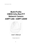
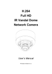
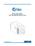
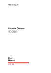
3 Mega-Pixel Vari-Focal IR / Fisheye IP Camera
ICA-3350V / ICA-5350V / ICA-8350
Quick Installation Guide
Table of Contents
Chapter 1. Introduction..................................................................................... 3
1.1 Before Installation................................................................................ 3
1.2 System Requirements........................................................................... 3
Chapter 2. Physical Description and Installation................................................... 4
2.1 ICA-3350V 3 Mega-Pixel Vari-Focal Bullet IR IP Camera........................... 4
2.1.1 Package Content......................................................................... 4
2.1.2 Physical Details........................................................................... 4
2.1.3 Installation................................................................................. 6
2.2 ICA-5350V 3 Mega-Pixel Vandal Proof IR IP Camera................................ 7
2.2.1 Package Content......................................................................... 7
2.2.2 Physical Details........................................................................... 7
2.2.3 Installation................................................................................. 9
2.3 ICA-8350 3 Mega-Pixel Vandal Proof Fisheye IP Camera.........................10
2.3.1 Package Content........................................................................10
2.3.2 Physical Details..........................................................................10
2.3.3 Installation................................................................................12
Chapter 3. Camera Windows Utility...................................................................13
Further Information.........................................................................................16
Chapter 1. Introduction
Thank you for purchasing the PLANET 3 Mega-Pixel Vari-Focal IR / Fisheye IP
Camera. It is versatile and high image solution of surveillance application for
day and night. The PLANET IP Camera support Multi-Profile function can stands
for simultaneously video streams. These Network Cameras can generate H.264,
MPEG-4 and M-JPEG streaming simultaneously to different clients. Moreover, the
resolution can be different from one client to another. This state-of-art design is
considerable to fit in various network environments.
1.1 Before Installation
Before installation, please be sure to read this quick installation guide and user’s
manual (CD) carefully to complete machine installation. This guide shows how to
quick set up these cameras, unless model name specified terms “IP Camera” will
be used for these three models.
1.2 System Requirements
CPU
Intel Dual Core 2.4GHz or higher
RAM
2GB (above Recommended)
Video RAM
256MB (above Recommended)
Display Resolution
1280x1024 24bits or above
Operating System
Windows XP / Vista / Win7
DirectX
10 or above
Network
Wired Ethernet 100Base-TX
3
Chapter 2. Physical Description and Installation
2.1 ICA-3350V 3 Mega-Pixel Vari-Focal Bullet IR IP Camera
2.1.1 Package Content
ICA-3350V x 1
Power Adapter x 1
Accessory Kit x 1
User’s Manual CD x 1
Quick Installation Guide x 1
Note
If any of the above items are missing, please contact your dealer
immediately.
2.1.2 Physical Details
ICA-3350V Connector
12V
DI
GND
DO
485+
485-
DI/DO
1
2
3
4
5
6
VIDEO
Color Pink
MIC
Color Green
AUDIO
+
DC
–
Orange
LED
8
RJ-45
1
Green
LED
RESET
4
Interface
RJ45 LAN
socket
Description
Connects to your local area network by Ethernet cable.
LAN LED (green color)
This LED will be flashing while network accessing via Ethernet.
Power LED (orange color)
This LED is used to indicate whether DC power is on or not.
DC power input, connect to AC power adapter.
DC-in Jack
Note
To ensure maximum compatibility, use only the power
adapter that came with your product. Otherwise, the
product may be damaged.
RS-485: Connect to a local keyboard controller.
DI/ DO: Connect to sensor in and alarm out devices.
Cable for I/O connectors:
Name
RS-485 &
Digital I/O
Number
Function
12VDC
1
DC 12V (50mA maximum)
DI
2
Digital signal input
GND
3
GND
DO
4
Digital signal output
485+
5
RS485 data +
485-
6
RS485 data -
MIC in
(Audio in)
Connect a microphone to the network camera.
Audio out
Connect a loud speaker to the network camera. This function is
for voice alerting and two-way audio.
Video out
(BNC
connector)
The Network Camera also provides composite video output.
The video output function is only for easy installation to check
view angle and focus. The output is not a Mega-Pixel resolution.
Furthermore, only “720P Mode” supports this function. “2 Mega
Mode” does not support it. Please refer to Setting \ Video \
Common chapter.
5
Reset
This button is used to restore the all factory default settings.
Sometimes restarting the device will make the system back to
a normal state. However, if the system still got problems after
restart, user can restore the factory default settings and install it
again.
Restore the device:
1.While the Camera is ready and then press the button down
continuously.
2.Hold the button at least 5 seconds and release it. Then the
device has been restored to default settings and reboot again.
Note
Restoring the factory default setting will lose the all
previous settings included IP address forever. User
needs to run the IPWizard II program to search the
device and configure it to let the device work properly
again.
2.1.3 Installation
1.Fix IR camera to desired location with wall mount fixture.
2.Plug-in Ethernet Cable into RJ-45 connector.
Connect an Ethernet cable to the LAN socket located on the Network Camera’s
back panel and attach it to the network.
3.Connect RS485 D+ and D- (if you need to control PT scanner).
4.Connect the attached power adapters to camera and heater (option/by model)
and plug-in these adapters into power outlet.
5.Done.
6
2.2 ICA-5350V 3 Mega-Pixel Vandal Proof IR IP Camera
2.2.1 Package Content
ICA-5350V x 1
Power Adapter x 1
Accessory Kit x 1
User’s Manual CD x 1
Quick Installation Guide x 1
Note
If any of the above items are missing, please contact your dealer
immediately.
2.2.2 Physical Details
ICA-5350V Connector
12V
DI
GND
DO
485+
485-
DI/DO
1
2
3
4
5
6
VIDEO
Color Pink
MIC
Color Green
AUDIO
+
DC
–
Orange
LED
8
RJ-45
1
Green
LED
RESET
7
Interface
RJ45 LAN
socket
Description
Connects to your local area network by Ethernet cable.
LAN LED (green color)
This LED will be flashing while network accessing via Ethernet.
Power LED (orange color)
This LED is used to indicate whether DC power is on or not.
DC power input, connect to AC power adapter.
DC-in Jack
Note
To ensure maximum compatibility, use only the power
adapter that came with your product. Otherwise, the
product may be damaged.
RS-485: Connect to a local keyboard controller.
DI/ DO: Connect to sensor in and alarm out devices.
Cable for I/O connectors:
Name
RS-485 &
Digital I/O
Number
Function
12VDC
1
DC 12V (50mA maximum)
DI
2
Digital signal input
GND
3
GND
DO
4
Digital signal output
485+
5
RS485 data +
485-
6
RS485 data -
MIC in
(Audio in)
Connect a microphone to the network camera.
Audio out
Connect a loud speaker to the network camera. This function is
for voice alerting and two-way audio.
Video out
(BNC
connector)
The Network Camera also provides composite video output.
The video output function is only for easy installation to check
view angle and focus. The output is not a Mega-Pixel resolution.
Furthermore, only “720P Mode” supports this function. “2 Mega
Mode” does not support it. Please refer to Setting \ Video \
Common chapter.
8
Reset
This button is used to restore the all factory default settings.
Sometimes restarting the device will make the system back to
a normal state. However, if the system still got problems after
restart, user can restore the factory default settings and install it
again.
Restore the device:
1.While the Camera is ready and then press the button down
continuously.
2.Hold the button at least 5 seconds and release it. Then the
device has been restored to default settings and reboot again.
Note
Restoring the factory default setting will lose the all
previous settings included IP address forever. User
needs to run the IPWizard II program to search the
device and configure it to let the device work properly
again.
2.2.3 Installation
1.Fix IR camera to desired location with wall mount fixture.
2.Plug-in Ethernet Cable into RJ-45 connector.
Connect an Ethernet cable to the LAN socket located on the Network Camera’s
back panel and attach it to the network.
3.Connect RS485 D+ and D- (if you need to control PT scanner).
4.Connect the attached power adapters to camera and heater (option/by model)
and plug-in these adapters into power outlet.
5.Done.
9
2.3 ICA-8350 3 Mega-Pixel Vandal Proof Fisheye IP Camera
2.3.1 Package Content
ICA-8350 x 1
Power Adapter x 1
Accessory Kit x 1
User’s Manual CD x 1
Quick Installation Guide x 1
Note
If any of the above items are missing, please contact your dealer
immediately.
2.3.2 Physical Details
ICA-8350 Connector
12V
DI
GND
DO
485+
485-
DI/DO
1
2
3
4
5
6
VIDEO
Color Pink
MIC
Color Green
AUDIO
+
DC
–
Orange
LED
8
RJ-45
1
Green
LED
RESET
10
Interface
RJ45 LAN
socket
Description
Connects to your local area network by Ethernet cable.
LAN LED (green color)
This LED will be flashing while network accessing via Ethernet.
Power LED (orange color)
This LED is used to indicate whether DC power is on or not.
DC power input, connect to AC power adapter.
DC-in Jack
Note
To ensure maximum compatibility, use only the power
adapter that came with your product. Otherwise, the
product may be damaged
RS-485: Connect to a local keyboard controller.
DI/ DO: Connect to sensor in and alarm out devices.
Cable for I/O connectors:
Name
RS-485 &
Digital I/O
Number
Function
12VDC
1
DC 12V (50mA maximum)
DI
2
Digital signal input
GND
3
GND
DO
4
Digital signal output
485+
5
RS485 data +
485-
6
RS485 data -
MIC in
(Audio in)
Connect a microphone to the network camera.
Audio out
Connect a loud speaker to the network camera. This function is
for voice alerting and two-way audio.
Video out
(BNC
connector)
The Network Camera also provides composite video output.
The video output function is only for easy installation to check
view angle and focus. The output is not a Mega-Pixel resolution.
Furthermore, only “720P Mode” supports this function. “2 Mega
Mode” does not support it. Please refer to Setting \ Video \
Common chapter.
11
Reset
This button is used to restore the all factory default settings.
Sometimes restarting the device will make the system back to
a normal state. However, if the system still got problems after
restart, user can restore the factory default settings and install it
again.
Restore the device:
1.While the Camera is ready and then press the button down
continuously.
2.Hold the button at least 5 seconds and release it. Then the
device has been restored to default settings and reboot again.
Note
Restoring the factory default setting will lose the all
previous settings included IP address forever. User
needs to run the IPWizard II program to search the
device and configure it to let the device work properly
again.
2.3.3 Installation
1.Fix IR camera to desired location with wall mount fixture.
2.Plug-in Ethernet Cable into RJ-45 connector.
Connect an Ethernet cable to the LAN socket located on the Network Camera’s
back panel and attach it to the network.
3.Connect RS485 D+ and D- (if you need to control PT scanner).
4.Connect the attached power adapters to camera and heater (option/by model)
and plug-in these adapters into power outlet.
5. Done.
12
Chapter 3. Camera Windows Utility
This chapter shows how to quick set up your 3 Mega-Pixel Vari-Focal IR / Fisheye
IP Camera. The 3 Mega-Pixel Vari-Focal IR / Fisheye IP Camera is with the default
settings. However to help you find the networked camera quickly the windows
utility (PLANET IPWizard II) can search the IP cameras in the network that shall
help you to configure some basic setting before you started advanced management
and monitoring.
Please insert the bundle CD disk into your CD/DVD-ROM drive. When the welcome
web page appears, please click your IP camera name on the IP camera list. Then
click the PLANET IPWizard II hyperlink to start the PLANET IPWizard II.
Search function:
Press “Search” button. PLANET IPWizard II will list all networked devices in the
LAN. If the IP camera doesn’t be found, you may check this IP camera is connect
to network properly and press the search button again.
13
View function:
If PLANET IPWizard II finds network devices, View button will be available. Please
select the device you want to view and click the View button. Furthermore you
could double click the left button of mouse to link to the network device by
browser.
LAN setting:
The utility featured with “LAN” setting function to help user to modify the IP
parameters of the installed network devices. User can step by step to setup IP
address, username and password.
Note
14
1.If no IP address is assigned within 30 seconds, the networked
device will automatically assign 192.168.0.20. User may now
open your web browser, and key in http://192.168.0.20 in
the address bar of you web browser to logon IP Camera’s web
configuration page.
2.Power Line Frequency
- If you found the video image is flash, you may need to choose
50 or 60 Hz frequency (depends on different country).
- World wide power line frequency table is inside user’s manual,
Appendix.
After connected to networked device, the device will prompt for User name and
Password. For the first time, please enter: admin/admin as username and
password to continue Web Management.
XXXXX
Default User Name: admin
Default Password: admin
Default IP: 192.168.0.20 – if no DHCP existed in the network
If difficulty is met, please refer to the following steps to establish the connection:
- The networked device must be installed and powered ON.
If the networked device’s default IP Address (192.168.0.20) is already used by
another device, the other device must be turned OFF until the device is allocated a
new IP Address during configuration.
15
Further Information
This guide is used to help you startup your IP Camera settings. It is also
recommended to check the user manual in CD disk for more details of the system
and user configuration.
16