1
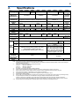
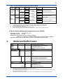
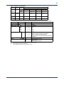
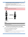
User’s Manual PH4/OR4 Sensor Series pH and ORP Sensors IM 12B10B00-01EN IM 12B10B00-01EN 1st Edition i Introduction Thank you for purchasing the PH4/OR4 Sensor Series pH and ORP Sensors. Please read the following respective documents before installing and using the sensors. This manual is applied to the following sensors; PH4P PH4PT OR4P PH4F PH4FT PH4C PH4CT OR4C PH4FE Polymer Electrolyte pH Sensor Polymer Electrolyte pH Sensor with RTD Polymer Electrolyte ORP Sensor HF-Resistant pH Sensor HF-Resistant pH Sensor with RTD pH Sensor for Chemical Process pH Sensor for Chemical Process with RTD ORP Sensor for Chemical Process pH Sensor for Fermentation Other relevant models are described in the following manuals. Equipment Holder Model PH8HS PH8HF Adapter ― SA405 Transmitter FLXA21 PH450G Terminal box WTB10 Distributor PH201G Model name Submersion type holder Flow-through type holder (Option code) Adapter with temperature sensor 2-Wire Analyzer pH/ORP Converter Terminal box Distributor VJA1, MA1, etc. Distributor Accessories PH8AX OR8AX Accessories for pH meter Accessories for ORP meter Manual IM 12B07M01-E (this manual) IM 12A01A02-01E etc. IM 12B07C05-01E IM 19D01B01-01E IM 19B01E04-02E IM 77J01A01-01E, IM 77J04A01-01E etc. IM 12B07W03-01E IM 12C04W02-01E Check the following when you receive the product: • Appearance • Model Name (on nameplate of sensor) and Suffix Codes (on nameplate of packing box) If you have any questions, contact our sales representative or your local distributor. n Notes on Handling User’s Manuals • Please hand over the user’s manuals to your end users so that they can keep the user’s manuals on hand for convenient reference. • Please read the information thoroughly before using the product. • The purpose of these user’s manuals is not to warrant that the product is well suited to any particular purpose but rather to describe the functional details of the product. • No part of the user’s manuals may be transferred or reproduced without prior written consent from YOKOGAWA. • YOKOGAWA reserves the right to make improvements in the user’s manuals and product at any time, without notice or obligation. • If you have any questions, or you find mistakes or omissions in the user’s manuals, please contact our sales representative or your local distributor. • Some drawings may be partially emphasized, simplified, or omitted, for the convenience of description. Media No. 12B10B00-01EN 1st Edition : Aug. 2015 (YK) All Rights Reserved Copyright © 2015, Yokogawa Electric Corporation IM 12B10B00-01EN 1st Edition : Aug. 12, 2015-00 ii Safety Precautions n Safety, Protection, and Modification of the Product • In order to protect the system controlled by the product and the product itself and ensure safe operation, observe the safety precautions described in this user’s manual. We assume no liability for safety if users fail to observe these instructions when operating the product. • If this instrument is used in a manner not specified in this user’s manual, the protection provided by this instrument may be impaired. • If any protection or safety circuit is required for the system controlled by the product or for the product itself, prepare it separately. • Be sure to use the spare parts approved by Yokogawa Electric Corporation (hereafter simply referred to as YOKOGAWA) when replacing parts or consumables. • Modification of the product is strictly prohibited. • The following words are used in this manual. CAUTION This symbol gives information essential for understanding the operations and functions. NOTE This symbol indicates information that complements the present topic. n Warning and Disclaimer The product is provided on an “as is” basis. YOKOGAWA shall have neither liability nor responsibility to any person or entity with respect to any direct or indirect loss or damage arising from using the product or any defect of the product that YOKOGAWA can not predict in advance. IM 12B10B00-01EN 1st Edition : Aug. 12, 2015-00 iii PH4/OR4 Sensor Series pH and ORP Sensors IM 12B10B00-01EN 1st Edition CONTENTS Introduction...............................................................................................................i Safety Precautions...................................................................................................ii 1.Application.....................................................................................................1 2. Specifications................................................................................................2 3. Model and Suffix Codes................................................................................3 4. Wiring Diagrams............................................................................................8 5.Dimensions....................................................................................................9 6.Use............................................................................................................... 12 6.1Preparing............................................................................................................. 12 6.2 Electrical wiring................................................................................................... 12 6.3 Procedure for Assembling of Sensor into Holder........................................... 13 6.4Storage................................................................................................................. 14 6.5Regenerating....................................................................................................... 14 6.6General................................................................................................................. 14 Revision Record.................................................................................................... 15 IM 12B10B00-01EN 1st Edition : Aug. 12, 2015-00 Blank Page 1 1.Application l Selection of pH sensor pH sensor PH4P Application PH4PT Contaminating and sulfide ion containing solutions ○ Caustic electrolysis solutions × Solutions containing organic solvents × Waste water containing hydrofluoric acid *1 × Fermentation (sterilization process) × PH4F PH4FT × × × ○ × PH4C PH4CT × ○ ○ × × PH4FE × × ○ × ○ *1: Confirm the specifications of hydrofluoric acid concentration upper limit. Note: This table above is just for reference. Consult sales personnel about selection of pH sensor. l Selection of ORP sensor Application ORP sensor Cyanogen treatment Chrome treatment Contaminating and sulfide ion containing solutions Caustic electrolysis solutions Drainage treatment OR4P Platinum × × ○ × OR4C Platinum × ○ × ○ Note: This table above is just for reference. Consult sales personnel about selection of pH sensor. IM 12B10B00-01EN 1st Edition : Aug. 12, 2015-00 2 2. Specifications PH4P OR4C PH4FE -1500 to pH 0 to 12 +1500 mV 0 to 105°C (Sterilization Measuring 0 to 110°C 0 to 80°C 0 to 100°C temperature: temperature *2 maximum 130°C) Measuring Atmospheric pressure to 1.6MPa (Temperature 25°C) Atmospheric pressure to Atmospheric pressure *2 Atmospheric pressure to 600kPa (Temperature 100°C) 250kPa *3 pressure to 600kPa Viscous 3M Electrolyte inner Polymer electrolyte including KCl *4 High viscosity gel including KCl KCl-LR solution None None RTD None None Pt1000 None Pt1000 Pt1000 None *5 *5, *6 *5, *6 (Temperature element) *5, *6 Ceramic Diaphragm Open junction x 2 Ceramic junction x 1 junction x 3 Head form S8 VP6 S8 S8 VP6 S8 VP6 S8 S7 Cable S8/S7 VP6 S8/S7 VP6 S8/S7 VP6 S8/S7 Cable jacket Polyvinyl Chloride (PVC) material -30 to -20 to -30 to Cable measuring -20 to -30 to -20 to 70°C -20 to 70°C 70°C 70°C 70°C temperature 70°C 70°C 120, 200, Insertion Length 120 mm 250 mm *7 Glass tube 12 mm diameter Glass, Glass, Glass Glass Body Glass platinum platinum O-ring Ethylene Propylene Diene Rubber Fluororubber (FPM) ― *8 (EPDM) Wetted Stainless steel (SUS316) (option part code: /S3), Polypropylene (option Stainless steel (SUS316) (option code: /S3), material code: /PP), Rigid polyvinyl chloride Adapter Polypropylene (option code: /PP) ― (option code: /PV), Heat-resistant or Rigid polyvinyl chloride (option code: /PV) Vinyl Chloride (option code: /HPV) or titanium (option code: /TN) ORP element ― Pt (Wire) ― Pt (Ring) ― Reference electrode None Available (Silver ion trap) Applicable Flow-through holder (PH8HF), Submersion holder (PH8HS) *9 *10 holder Measuring range PH4PT pH 2 to 14 OR4P -1500 to +1500 mV PH4F PH4FT pH 2 to 11 *1 PH4C PH4CT pH 0 to 14 Note: Above sensors cannot be used outdoors or with a guide holder. Installation from lower position or a horizontal position is not possible. Install to the vertical position of more than 15 degrees against the horizontal portion. *1: The upper limitation of hydrofluoric concentration is below pH 3 to 4 Maximum 1000 ppm pH 4 to 5 Maximum 10000 ppm Over pH 5 No upper limitation *2: See Table 1 when using with holder (excluding PH4FE) *3: PH4C, PH4CT and OR4C are subject to restriction of the inner pressure which remains in the sensor *4: When used in solution contains organic solvents, Polymer may be eroded and cannot be used for long term. *5: Select manual temperature compensation on the converter or transmitter. *6: Use adapter with temperature sensor SA405 for application where temperature varies *7: Shaft Length in case of PH4FE *8: Option code “/PF” Perfluoroelastomer (FFKM) can be selected for O-ring material when used pH sensor (excluding PH4FE) *9: An option adapter is needed, but not needed when using the adapter with temperature sensor SA405. Ultrasonic cleaning is not available. Use a holder with jet cleaning equipment when automatic cleaning is necessary. Use O-ring covered by Teflon (K9148MR) when using a special holder for electrolytic process for PH4C, PH4CT or OR4C. *10: PH4FE cannot be used with PH8HF or PH8HS. When a holder is needed, consult sales personnel. IM 12B10B00-01EN 1st Edition : Aug. 12, 2015-00 3 Table 1 Process Temperature Range, Process Pressure Range Adapter Material PVC PP, SUS None Submersion PP, SUS *2 PVC (PH8HS) *2 Provided *3 PP, SUS *2 PVC None, PP, SUS PP Provided *3 *2 FlowPVC None PP through SUS *2 (PH8HF) *1 SUS *2 PP, SUS Provided *3 *2 PVC Holder Type Holder Material Cleaner pH/ORP Range Temperature (°C) 0 to 50 0 to 100 *4 PH4P, PH4PT: pH 2 to 14 0 to 50 Process Pressure Atmospheric pressure (Submersion depth: Max. 3m) 0 to 80 PH4F, PH4FT: pH 2 to 11 0 to 50 0 to 80 PH4C, PH4CT: 0 pH 0 to 14 to 50 0 to 80 0 to 100 *4 OR4P, OR4C: -1500 to 1500 mV 0 to 80 PH4P, PH4PT, OR4P PH4F, PH4FT: Atmospheric pressure to 500 kPa PH4C, PH4CT, OR4C *5: Atmospheric pressure to 250 kPa 0 to 50 PVC: Rigid Polyvinyl Chloride, PP: Polypropylene, SUS: Stainless Steel (SUS316) *1: For Flow-through types also refer to temperature and pressure diagram of Holder GS 12J05C02-00E. *2: Stainless steel holder and stainless steel adapter should be used if the solution is pH 3 more acidmic. *3: Only jet cleaning system can be used. *4: When PH4F or PH4FT is used, temperature upper limit is 80°C. *5: Available measuring pressure decreases when the inner pressure of PH4C, PH4CT or OR4C decreases. l Specification for adapter with temperature sensor (SA405) Applicable sensors: PH4P, PH4F, PH4C Temperature sensor: Pt1000 Wetted part (Temperature sensor / Adapter) materials : Hastelloy C / Hastelloy C, Stainless steel (SUS316) / PEEK, titanium / titanium Applicable holder: Flow-through holder (PH8HF), Submersion holder (PH8HS) 3. Model and Suffix Codes Model PH4P PH4PT PH4F PH4FT Insertion Length Cable Length Terminal Type *3 ― Option *1: *2: *3: *4: *5: Suffix Code ........................ ........................ ........................ ........................ -120 Option Code ....................... ....................... ....................... ....................... ....................... ....................... ....................... ....................... ....................... ....................... ....................... D ....................... E ....................... F ....................... G ....................... N ....................... -N ....................... Adapter *4 /S3 /PP /PV O-Ring /PF -00 -03 -05 -10 -15 -20 Specifications Polymer Electrolyte pH Sensor *1 Polymer Electrolyte pH Sensor with RTD HF-Resistant pH Sensor *1 HF-Resistant pH Sensor with RTD 120 mm No Cable *2 3m 5m 10 m 15 m 20 m Cable for PH400G (Fork Terminal) Cable for PH202, FLXA21 (Pin Terminal) Cable for FLXA21 (M4 Ring Terminal) Cable for PH450G, PH202/TB (M3 Ring Terminal) No Cable *2 Always -N Stainless Steel (SUS316) Polypropylene Rigid Polyvinyl Chloride Perfluoroelastomer (FFKM) *5 PH4P and PH4F can be used with the adapter with temperature sensor SA405. When using sensor only, select cable length -00 and Terminal type N. When using Terminal box, refer to Table 2. This is needed when using the holder PH8HS or PH8HF. However when PH4P or PH4F is used with the temperature sensor SA405, the option adapter is not needed. Select perfluoroelastomer when sensor is used in organic solvent, high alkaline or high temperature alkaline solution. IM 12B10B00-01EN 1st Edition : Aug. 12, 2015-00 4 Table 2 Selection of terminal box Sensor RTD SA405 PH4P Selected PH4F None None PH4C PH4PT PH4FT Available ― PH4CT OR4P None ― OR4C PH4FE None ― D ― Terminal Type E F G WTB10-PH2 WTB10-PH6 WTB10-PH4 ― WTB10-PH1 WTB10-PH5 WTB10-PH3 ― WTB10-PH1 WTB10-PH5 WTB10-PH3 ― WTB10-PH1 WTB10-PH5 WTB10-PH3 ― ― ― ― Note: For combined system with WTB10, maximum cable length including sensor cable length should be within 20 m. Model Suffix Code Option Code Specifications OR4P ........................ ....................... Polymer Electrolyte ORP Sensor Insertion Length -120 ....................... 120 mm Cable Length Terminal Type *2 ― Option *1: *2: *3: ....................... ....................... ....................... ....................... ....................... ....................... D ....................... E ....................... F ....................... G ....................... N ....................... -N ....................... Adapter *3 /S3 /PP /PV -00 -03 -05 -10 -15 -20 No Cable *1 3m 5m 10 m 15 m 20 m Cable for PH400G (Fork Terminal) Cable for PH202, FLXA21 (Pin Terminal) Cable for FLXA21 (M4 Ring Terminal) Cable for PH450G, PH202/TB (M3 Ring Terminal) No Cable *1 Always -N Stainless Steel (SUS316) Polypropylene Rigid Polyvinyl Chloride When using sensor only, select cable length -00 and Terminal type N. When using Terminal box, refer to Table 2. This is needed when using the holder PH8HS or PH8HF. IM 12B10B00-01EN 1st Edition : Aug. 12, 2015-00 5 Model Suffix Code Option Code Specifications PH4C ........................ ....................... pH Sensor for Chemical Process *1 PH4CT ........................ ....................... pH Sensor for Chemical Process with RTD Insertion Length -120 ....................... 120 mm Cable Length Terminal Type *3 ― Option *1: *2: *3: *4: *5: ....................... ....................... ....................... ....................... ....................... ....................... D ....................... E ....................... F ....................... G ....................... N ....................... -N ....................... Adapter *4 /S3 /PP /PV /HPV /TN O-Ring /PF -00 -03 -05 -10 -15 -20 No Cable *2 3m 5m 10 m 15 m 20 m Cable for PH400G (Fork Terminal) Cable for PH202, FLXA21 (Pin Terminal) Cable for FLXA21 (M4 Ring Terminal) Cable for PH450G, PH202/TB (M3 Ring Terminal) No Cable *2 Always -N Stainless Steel (SUS316) Polypropylene Rigid Polyvinyl Chloride Heat-resistant Vinyl Chloride Titanium Perfluoroelastomer (FFKM) *5 PH4C can be used with the adapter with temperature sensor SA405. When using sensor only, select cable length -00 and Terminal type N. When using Terminal box, refer to Table 2. This is needed when using the holder PH8HS or PH8HF. However when PH4C is used with the temperature sensor SA405, the option adapter is not needed. Select perfluoroelastomer when sensor is used in organic solvent, high alkaline or high temperature alkaline solution. Model Suffix Code Option Code Specifications OR4C ........................ ....................... ORP Sensor for Chemical Process Insertion Length -120 ....................... 120 mm Cable Length Terminal Type *2 ― Option *1: *2: *3: ....................... ....................... ....................... ....................... ....................... ....................... D ....................... E ....................... F ....................... G ....................... N ....................... -N ....................... Adapter *3 /S3 /PP /PV /HPV /TN -00 -03 -05 -10 -15 -20 No Cable *1 3m 5m 10 m 15 m 20 m Cable for PH400G (Fork Terminal) Cable for PH202, FLXA21 (Pin Terminal) Cable for FLXA21 (M4 Ring Terminal) Cable for PH450G, PH202/TB (M3 Ring Terminal) No Cable *1 Always -N Stainless Steel (SUS316) Polypropylene Rigid Polyvinyl Chloride Heat-resistant Vinyl Chloride Titanium When using sensor only, select cable length -00 and Terminal type N. When using Terminal box, refer to Table 2. This is needed when using the holder PH8HS or PH8HF. IM 12B10B00-01EN 1st Edition : Aug. 12, 2015-00 6 Model PH4FE Shaft Length Suffix Code ........................ -120 -200 -250 Cable Length -00 -03 -05 -10 -15 -20 Terminal Type D E N ― -N *1: Option Code ....................... ....................... ....................... ....................... ....................... ....................... ....................... ....................... ....................... ....................... ....................... ....................... ....................... ....................... Specifications pH Sensor for Fermentation 120 mm 200 mm 250 mm No Cable *1 3m 5m 10 m 15 m 20 m Cable for PH400G (Fork Terminal) Cable for PH202, FLXA21 (Pin Terminal) No Cable *1 Always -N When using sensor only, select cable length -00 and Terminal type N. l Adapter with temperature sensor (SA405) Model SA405 Measuring System Suffix Code ........................ -A -E -F -G Material of Temp. -HC Sensor Cover/ -S3 Adapter -TN Cable Length -03 -05 -10 -15 -20 *1: *2: *3: *4: Option Code ....................... ....................... ....................... ....................... ....................... Specifications Adapter with temperature sensor for PH400G *1 for PH202/FLXA21 *2 for FLXA21 *4 for PH450G,PH202/TB *3 ....................... ....................... ....................... ....................... ....................... ....................... ....................... ....................... Hastelloy C / Hastelloy C Stainless steel (SUS316) / PEEK Titanium / Titanium 3m 5m 10 m 15 m 20 m Mark band is shown by alphabet and fork terminals are used. Mark band is shown by numeral and pin terminals are used. When terminal box is used, select WTB10-PH2. Mark band is shown by numeral and M3 ring terminals are used. When terminal box is used, select WTB10-PH4. Mark band is shown by numeral and M4 ring terminals are used. When terminal box is used, select WTB10-PH6. l Spare Parts Part Name Fork Terminal Cable for PH400G, OR400G Terminal Type: D 3m 5m 10 m 15 m 20 m 3m 5m 10 m 15 m 20 m Part Number K9691MA K9691MB K9691MC K9691MD K9691ME K9691NA K9691NB K9691NC K9691ND K9691NE Remarks For PH4P, OR4P, PH4F, PH4C, OR4C, PH4FE For PH4PT, PH4FT, PH4CT IM 12B10B00-01EN 1st Edition : Aug. 12, 2015-00 7 Part Number 3m K9691PA 5m K9691PB 10 m K9691PC 15 m K9691PD Pin Terminal Cable for 20 m K9691PE PH202, FLXA21 3m K9691QA Terminal Type: E 5m K9691QB 10 m K9691QC 15 m K9691QD 20 m K9691QE 3m K9691RA 5m K9691RB 10 m K9691RC 15 m K9691RD M4 Ring Terminal 20 m K9691RE Cable for FLXA21 3m K9691RN Terminal Type: F 5m K9691RP 10 m K9691RQ 15 m K9691RR 20 m K9691RS 3m K9691SA 5m K9691SB 10 m K9691SC M3 Ring Terminal 15 m K9691SD Cable for PH450G, 20 m K9691SE PH202/TB 3m K9691SN 5m K9691SP Terminal Type: G 10 m K9691SQ 15 m K9691SR 20 m K9691SS Stainless Steel (SUS316) K9148NA Option code: /S3 Polypropylene K9148NB Option code: /PP Rigid Polyvinyl Chloride K9148NC Adapter Option code: /PV Heat-resistant Vinyl K9148ND Chloride Option code: /HPV Titanium K9148NE Option code: /TN Perfluoroelastomer K9319RJ (FFKM) O-Ring Fluororubber (FPM) K9691KA Ethylene Propylene K9691KB Diene Rubber (EPDM) Electrolyte Viscous 3 M KCl-LR K9691KK Buffer solution for calibration (pH4) K9084LL K9084LM Buffer solution for calibration (pH7) K9084LN Buffer solution for calibration (pH9) Powder for buffer solution (pH4) K9020XA Powder for buffer solution (pH7) K9020XB Powder for buffer solution (pH9) K9020XC Reagent for ORP Quinhydrone K9024EC check Iron K9024ED Remarks Part Name For PH4P, OR4P, PH4F, PH4C, OR4C, PH4FE For PH4PT, PH4FT, PH4CT For PH4P,OR4P, PH4F, PH4C, OR4C For PH4PT, PH4FT, PH4CT For PH4P, OR4P, PH4F, PH4C, OR4C For PH4PT, PH4FT, PH4CT For PH4P, PH4PT, OR4P, PH4F, PH4FT, PH4C, PH4CT, OR4C For PH4C, PH4CT, OR4C For PH4P, PH4PT, PH4F, PH4FT, PH4C, PH4CT, Option code: /PF For PH4P, PH4PT, OR4P, PH4F, PH4FT For PH4C, PH4CT, OR4C For PH4FE (500mL) Six 250 mL polyethylene bottles Six 250 mL polyethylene bottles Six 250 mL polyethylene bottles 12 bags, each for preparation of 500 mL 12 bags, each for preparation of 500 mL 12 bags, each for preparation of 500 mL 3 bags, each for preparation of 250 mL 3 bags, each for preparation of 250 mL Note: The pH value of the calibrating buffer solution may vary depending on storage conditions. IM 12B10B00-01EN 1st Edition : Aug. 12, 2015-00 8 4. Wiring Diagrams Mark (alphabet / number) of cable core of pH sensor depends on terminal form. l In case of PH4, PH4FE pH sensor, OR4 ORP sensor Mark of cable core of pH sensor PH4P PH4F PH4C PH4FE OR4P OR4C GE (15) SE (14) RE (13) Mark of terminal of Converter/Transmitter FLXA21 PH400G PH202 PH450 16 S 15 GE 14 SE 13 RE 12 T2 11 T1 F01.ai Note: Since RTD is not available, there is no wire connection to Converter/Transmitter 11 (T1) or 12 (T2). There is no wire connection to Converter/Transmitter 16 (S). l In case of PH4T pH sensor with RTD Mark of cable core of pH sensor PH4PT PH4FT PH4CT GE SE SE RE T2 T1 (15) (14) (14) (13) (12) (11) Mark of terminal of Converter/Transmitter FLXA21 PH400G PH202 PH450 16 S 15 GE 14 SE 13 RE 12 T2 11 T1 F02.ai Note: 2 cable cores of pH sensor should be connected to the terminal of Converter/Transmitter 14 (SE). There is no wire connection to Converter/Transmitter 16 (S). l When using Terminal box WTB10 No combination with SA405 pH sensor with RTD WTB10-PH1, 3, 5 *1 Terminal Box pH Converter/ Transmitter 16 15 16 15 PH4P PH4F PH4C *2 13 12 11 14 13 12 11 14 Combination with SA405 WTB10-PH2, 4, 6 *1 Terminal Box PH4P PH4F PH4C SA405 *1: *2: 16 15 13 12 11 14 *2 WTB10-PH1, 3, 5 *1 Terminal Box pH Converter/ Transmitter 16 15 16 15 PH4PT PH4FT PH4CT *2 13 12 11 14 13 12 11 14 WTB10-PH1, 3, 5 *1 Terminal Box ORP Converter/ Transmitter 16 15 13 12 11 14 16 15 13 12 11 14 ORP sensor pH Converter/ Transmitter 16 15 13 12 11 14 OR4P OR4C *2 F03.ai Terminal box is used only where pH/ORP transmitter is installed remotely from pH or ORP sensor (normally not needed). Refer to Table 2 for WTB10 type. This cable is specified in the option code for the terminal box. IM 12B10B00-01EN 1st Edition : Aug. 12, 2015-00 9 5.Dimensions n PH4P Polymer Electrolyte pH Sensor PH4F HF-Resistant pH Sensor PH4C pH Sensor for Chemical Process 120 Approx. ø12 Unit: mm 32 S8 O-ring PG13.5 n PH4PT Polymer Electrolyte pH Sensor with RTD PH4FT HF-Resistant pH Sensor with RTD PH4CT pH Sensor for Chemical Process with RTD 120 Approx. ø12 VP6 O-ring PG13.5 n OR4P Polymer Electrolyte ORP Sensor 120 Approx. ø12 Unit: mm 32 S8 O-ring PG13.5 n OR4C ORP Sensor for Chemical Process 120 Approx. ø12 Unit: mm 52 Unit: mm 32 S8 O-ring PG13.5 IM 12B10B00-01EN 1st Edition : Aug. 12, 2015-00 10 n PH4FE pH Sensor for Fermentation L (L=120, 200, 250) Unit: mm 203 70 31 ø30 Approx. ø12 S7 Electrode solution (Inner solution) Inner solution refilling vent lCable S8/S7 cable for PH4P, OR4P, PH4F, PH4C, OR4C, PH4FE Approx. ø5 Unit: mm Approx. ø6.5 Approx. 100 Approx. 90 Cable length (approx. 3m, 5m, 10m, 15m, 20m) Terminal Type: D Terminal Type: E Terminal Type: F, G Note: There is no terminal type F or G for PH4FE. IM 12B10B00-01EN 1st Edition : Aug. 12, 2015-00 11 VP6 cable for PH4PT, PH4FT, PH4CT Unit: mm Cable length (approx. 3m, 5m, 10m, 15m, 20m) Approx. ø7.5 Terminal Type: D Terminal Type: E Terminal Type: F, G l Adapter (Option code: /S3, /PP, /PV, /HPV, /TN) Unit: mm ø38 ø26.5 16 18.5 42 15 5 ø12.5 ø30.5 IM 12B10B00-01EN 1st Edition : Aug. 12, 2015-00 12 l Adapter with temperature sensor (SA405) 132 105 18.5 Unit: mm (L+270)±50 ( L=3, 5, 10, 15, 20m ) ø5 Temperature sensor ø38 (Pt 1000) ø30.5 Ring terminal Pin terminal ø26.5 Adapter Temperature sensor cable Fork terminal 6.Use This sensor is only to be used for the intended purpose and under safe conditions. Improper use or misuse can be dangerous. CAUTION Since these sensors are made of glass, they should be handled with care. Take care that the PG13.5 thread and the O-ring are not damaged while the sensor is installed into the adapter etc. 6.1Preparing Carefully remove the storage cap by turning a screw located at a blue gasket. Rinse the sensor with water. Check the interior of the pH glass membrane for air bubbles. Allow any bubbles to rise to the top by shaking the sensor gently. PH4FE sensor: Prior to measuring, open the reservoir stopper; close it after measuring. Check level of electrolyte in the sensor. 6.2 Electrical wiring The sensors are equipped with a S8, S7 or a VP connector head. Before connecting the sensor to the cable, check that the connections are clean and dry. Do not touch the electrical contacts! Connectors especially should not be disconnected in moisture condensing environments. Unstable signals, low slope or long response time could indicate a moist or contaminated connector. Clean the connector head with a paper towel moistened with ethanol. Dry the connector head after this procedure with a dry paper towel. l Attaching/detaching method of sensor cable In case of VP connector • Rotating the sensor connector so that its recessed portions will agree with the salient portions inside the cable connector, insert the sensor connector into the cable connector. IM 12B10B00-01EN 1st Edition : Aug. 12, 2015-00 13 A weak pressure is sufficient for inserting it. If a strong pressure is needed to insert it, the connection position will be incorrect. Check the position and re-try. • After inserting the sensor connector completely, grip the portion “A”, and rotate the cap nut (“B” portion) clockwise until the nut cannot rotate. • Gripping the portion “A”, and rotate the cap nut (“B” portion) un-clockwise. • After loosing the nut completely, grip and pull the plastic portion of the sensor from the cable connector. CAUTION Do not grip or rotate the glass body of the sensor, but the plastic body of the connector. If the glass body is gripped, the sensor may be broken. A A B B Recess for positioning the sensor and cable (Sensor side) (Sensor side) Attaching/detaching NOTE If conduit is used, the metal part of the cable connector should not be in contact with metal parts of the conduit. If the metal part of the cable connector is in contact with other metal parts, this may cause measurement errors. 6.3 Procedure for Assembling of Sensor into Holder Install a sensor where a cable is connected according to 6.2 in a holder, when a holder is used. l For use of the model PH8HF flow-through holder (1) Remove the nut for fixing the sensor to the adapter. (2) Pass the cable through the nut. (3) Attach the O-ring attached inside the holder, to the adapter. (Refer to the O-ring position in below figure.) (4) Put the sensor into the holder, and fix the adapter by screwing the nut. IM 12B10B00-01EN 1st Edition : Aug. 12, 2015-00 14 l For use of the model PH8HS submersion holder (1) Remove the protector and piece of foam rubber. This rubber is for transportation. (2) Pass the O-ring through the cable, and mount it to the upper side of the adapter. (Refer to the O-ring position in below figure.) (3) Pass the cable through the holder from the protector attachment side, and fix the sensor by the protector. (4) Fix the sensor cable to the holder. Thread for attaching to the sensor O-Ring position for using the PH8HS holder O-Ring position for using the PH8HF holder Adapter 6.4Storage Sensors should be stored with the storage cap attached, containing 1.5 to 2 mL of 3.3 mol/L KCl solution. Sensors stored dry exhibit temporary drifting values. If the sensor dries out inadvertently, it can be placed in 3.3 mol/L KCl solution, or pH standard buffer solution overnight to regenerate. 6.5Regenerating Entire regenerating is not always guarantee. pH: Immerse sensor for 10 min in 0.1 – 1M NaOH, then for 10 min in 0.1 – 1M HCl. After regeneration, place the sensor in 3.3 mol/L KCl solution for a further 15 min. ORP: Metal surfaces can be cleaned with slightly abrasive substances, such as toothpaste or very fine scouring powder. 6.6General The life cycle of sensors is determined by requirements regarding response time, zero point and slope. Some of harsh measurement conditions might shorten life cycle. There is also a slight ageing factor during storage, therefore avoid a long period of storage. Use within a year is recommended. O-rings are subject to wear and tear and should be replaced regularly, at least once per year. Refer to “spare parts” regarding the parts number of O-rings. l For Models PH4C, PH4CT, OR4C The new sensor is pre-pressurized at about 250 kPa. This pressure, after one year, at the liquid junction, will decrease to about half at normal ambient temperatures and atmospheric pressure. Taking this decrease into account, use the sensor. If the pressure of a sample solution becomes higher than the inner pressure of the sensor, the solution will permeate gel electrolyte in the sensor. As a result, the sensor can become unusable. A rough change of the sensor inner pressure can be known by the air layer length of a narrow tube in the sensor. The higher the internal pressure, the shorter the air layer. l For with RTD (Models PH4PT, PH4FT, PH4CT) Sensors with a VP type connection have a built-in temperature sensor (Pt1000). This temperature sensor is to be used only to compensate the pH signal and not to control process temperature. IM 12B10B00-01EN 1st Edition : Aug. 12, 2015-00 15 Revision Record Manual Title : PH4/OR4 Sensor Series pH and ORP Sensors Manual No. : IM 12B10B00-01EN Aug. 2015/1st Edition Newly published IM 12B10B00-01EN 1st Edition : Aug. 12, 2015-00 Blank Page


![Model PH450G [Style: S2] pH and ORP Converter](http://vs1.manualzilla.com/store/data/006013412_1-cd77700eed276036ffccc744cbf6fbb4-150x150.png)