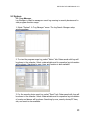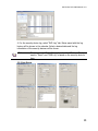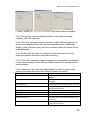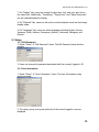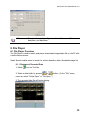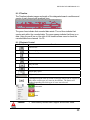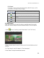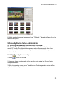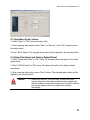
1
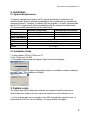
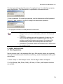
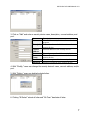
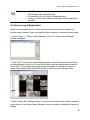
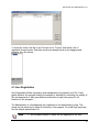
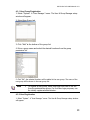
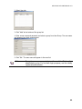
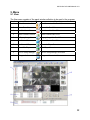
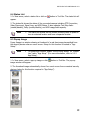
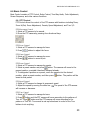
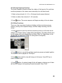
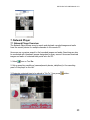
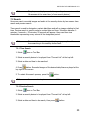
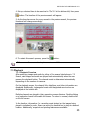
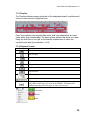
HD-SDI Professional DVR VMS Manual HD‐SDI Pro DVR VMS Manual v1.0 Preface Users installing and operating the product are required to understand this manual and related manuals fully before installation and operation. All rights of the software and hardware described in the manual are protected by the patent law. Note This icon indicates that the attached details explain procedures and provide additional information. Caution This icon indicates that the attached details express important information or limitations of the operation. 1 HD‐SDI Pro DVR VMS Manual v1.0 CONTENTS 1. OVERVIEW.........................................................................................................4 1.1 Introduction.............................................................................................4 1.2 Features....................................................................................................4 2. INSTALLATION.................................................................................................5 2.1 System Requirements..............................................................................5 2.2 Installation Guide....................................................................................5 3. SYSTEM LOGIN................................................................................................5 4. INITIAL INSTRUCTIONS................................................................................6 4.1 Site Registration......................................................................................6 4.2 Screen Layout Registration....................................................................8 4.3 User Registration.....................................................................................9 4.3.1 User Group Registration.........................................................10 4.3.2 User Registration......................................................................10 5. MENU.................................................................................................................12 5.1 View........................................................................................................12 5.2 System.....................................................................................................13 5.2.1 Log Manager............................................................................13 5.2.2 App Setup..................................................................................14 5.3 Setup.......................................................................................................16 5.3.1 Edit Password...........................................................................16 5.3.2 User Information......................................................................16 6. VIEWER.............................................................................................................17 6.1 Viewer Overview...................................................................................17 6.2 Image View.............................................................................................17 6.2.1 Image View By Connecting Security Devices........................17 6.2.2 Image View By Connecting Cameras.....................................18 6.2.3 Image View Through Second Monitor...................................18 6.3 Event List...............................................................................................18 6.4 Status List...............................................................................................19 6.5 Popup Image..........................................................................................19 6.6 Basic Control.........................................................................................20 6.6.1 PTZ Control..............................................................................20 6.6.2 Relay Out Control....................................................................21 6.6.3 Two-Way Audio Control.........................................................21 6.6.4 Color Adjustment.....................................................................21 6.6.5 Screen Sequence Function.......................................................21 6.6.6 Other Functions........................................................................22 7. NETWORK PLAYER......................................................................................23 7.1 Network Player Overview.....................................................................23 7.2 Search.....................................................................................................24 7.2.1 Time Search..............................................................................24 7.2.2 Preview Search.........................................................................24 7.3 Playback.................................................................................................25 2 HD‐SDI Pro DVR VMS Manual v1.0 7.3.1 Playback Overview..................................................................25 7.3.2 Timeline.....................................................................................26 7.3.3 Playback Control......................................................................26 7.3.4 Control......................................................................................26 7.4 Download................................................................................................27 8. FILE PLAYER..................................................................................................28 8.1 File Player Overview.............................................................................28 8.1.1 Playback of Recorded Data.....................................................28 8.1.2 Timeline.....................................................................................28 8.1.3 Playback Control......................................................................29 8.1.4 Control......................................................................................29 8.2 Smart Search.........................................................................................29 9. SECURITY DEVICE SETUP ADMINISTRATOR......................................31 9.1 Security Device Setup Administrator Overview.................................31 9.2 Initial Security Device Setup................................................................31 9.3 Open/Save Setup Values.......................................................................31 9.4 Setup Data Reset and Factory Default Reset......................................31 3 HD‐SDI Pro DVR VMS Manual v1.0 1 Overview 1.1 Introduction This program is a Central Management System designed to control various security devices (IP camera, DVR, NVR, Video Server, etc.) connected via a single PC by networking. This program handles multiple functions including live image monitoring, real-time event management, security device status monitoring, image search, playback, download, smart search, watermark, and so on. 1.2 Features In this program, users can register security devices without limitations on quantity, and it provides real-time monitoring of up to 128 cameras provided the VGA card in the PC supports two monitors. Users can control a function window size as each function has a separate window. This program manages user accounts and groups. It provides a separate management of user accounts by allowing the administrator the authority to set detail features for the group. This program manages and saves events sent by multiple security devices. This program reports to users alarms set for events via pop-up messages, audio, real-time images, and so on. In the network player, users can search recorded files and both play and download images and audio. Searches can be conducted by the second, and the preview screen enables users to search images without playing actual images. The recorded file containing images and audio on the PC can be played with the “File Player”; it provides a faster method to search for information with smart search and watermark. 4 HD‐SDI Pro DVR VMS Manual v1.0 2. Installation 2.1 System Requirements To properly operate this program, the PC requires specifications higher than the minimum listed. With the minimum specifications, the program can only operate with minimum functions. Therefore, to operate fully this program, it is highly recommended that the PC is equipped with higher specifications that the minimum as listed below. The recommended specifications are also listed below. Minimum Specifications Recommended Specifications Intel Core 2 Duo 2.0 GHz Intel Core 2 Quad 2.66 GHz CPU 2GB 4GB or higher Main Memory 128MB 512MB or higher Video Card Memory 1024 x 768 (with 32bit color) or higher Display Resolution 80GB or higher HDD Windows XP SP2 or higher OS 9.0 or higher DirectX 2.2 Installation Guide 1. Insert software CD into CD Drive of PC. 2. Run “Setup.exe” for VMS. 3. A language selected page will appear. Select the desired language. 4. Designate a folder for where the program ought to be installed or keep it at default, and click “Next.” The installation will begin. 3. System Login The system login screen determines whether the program should be executed or blocked based on whether the user name and password can be confirmed or not. 1. In the program start menu, navigate to the VMS and select its respective icon, or double-click the VMS icon on the desktop. The login window will appear. 5 HD‐SDI Pro DVR VMS Manual v1.0 2. In the login window, select the name of a registered user. For initial login purposes, select Administrator. The Administrator is registered as a fundamental user. 3. Enter a password. For initial login purposes, use the administrator default password “1111111.” After logging in, be sure to change the administrator password. 4. The program will start if a valid password was entered. Note To change the password, navigate to “Setup” “Password Change” menu. (For more information, refer to 5.2.9 Password Change.) In the VMS, multiple users can be registered; all users can log into one PC with separate user information. Each user may configure a preferred program environment; the program will start according to each user’s settings after the initial login. Information of the latest window environment will be saved when the program closes. 4. Initial Instructions 4.1 Site Registration Security devices need to be registered after login. After security devices are registered, users can use functions such as real-time monitoring, search and playback, backup, and event alarms. 1. Select “Setup” “Site Manager” menu. The Site Mager window will appear. 2. In Site Manager, Add, Delete, Modify, All Select, All Clear, and Properties functions are available. 6 HD‐SDI Pro DVR VMS Manual v1.0 3. Click on “Add” and enter a security device name, description, connect address, and port. Item Description Name of the security device to be used in the Name program Description Notes and other needed information on the security device Network address of the security device Connect Address Network port number of the security device Port The number of cameras connected to the Camera security device Count User Name User name registered in the security device Password registered in the security device Password 4. With “Modify,” users can change the security device’s name, connect address, and/or port. 5. With “Delete,” users can deleted selected sites. 6. Clicking “All Select” selects all sites and “All Clear” deselects all sites. 7 HD‐SDI Pro DVR VMS Manual v1.0 Note The VMS automatically initiates a connection to selected sites in Site Manager after successful login. A connection will not initiate for deselected sites. There is no limit to the number of sites that can be registered in the VMS. 4.2 Screen Layout Registration Screen Layout enables users to collect and monitor desired real-time images from various security devices. Users can register desired cameras in a desired channel mode. 1. Select “Setup” “Screen Layout Manager” menu. The Screen Layout Manager window will appear. 2. Click “Add.” In the Screen Layout Setting window, select the desired Channel Mode and drag cameras from the list on the left and drop them into desired panel locations on the right. The real-time monitoring images will appear. To register the layout, a Screen Layout Name and Channel Mode must be filled into their respective slots. 3. After finishing with adding cameras to the layout, users can check a newly registered screen layout in the Screen Layout Manager. Users can modify and delete the layout as desired. 8 HD‐SDI Pro DVR VMS Manual v1.0 4. Users can move a list tab in the Connect List to “Layout” and check a list of registered screen layouts. Real-time monitoring images show up by dragging-anddropping onto the screen. 4.3 User Registration User Registration allows registration and management of program’s user IDs. It will decide whether the program should be executed or blocked by confirming the validity of IDs and passwords; it also gives different authorities to each user group for all functions in the program. The Administrator is a fundamental user registered in the administrator group. This group has the authority to utilize all functions in the program. For initial login purposes, use the default administrator ID. Note An unlimited number of users can be registered in the VMS. 9 HD‐SDI Pro DVR VMS Manual v1.0 4.3.1 User Group Registration 1. Select “System” “User Manager” menu. The User & Group Manager setup window will appear. 2. Select User Group tab. 3. Click “Add” at the bottom of the group list. 4. Enter a group name and select the desired functions from the group permission list. 5. Click “OK”; the selected functions will be added to the user group. The name of the user group will be shown in the user group list. Note To register a user group, users must login with one of the IDs from the administrator group. For first time login purposes, use the initially registered administrator. 4.3.2 User Registration 1. Select “System” “User Manager” menu. The User & Group Manager setup window will appear. 10 HD‐SDI Pro DVR VMS Manual v1.0 2. Select User tab. 3. Click “Add” at the bottom of the group list. 4. Enter a user name and password and select a group from User Group. The user name and password are basic requirements. 5. Click “OK.” The user name will appear in the user list. Note To register a user, users must login with one of the IDs from the administrator group. For first time login purposes, use the initially registered administrator. 11 HD‐SDI Pro DVR VMS Manual v1.0 5. Menu 5.1 View The View menu consists of the panel window collection to be used in the program. Number Menu Icon Function 1 Site Connection List Site Connection List Panel View 2 Event List Event List Panel View 3 Site Status List Site Status List Panel View 4 Basic Control Function Basic Control Panel View 5 Pop-up Image List 6 Second Screen Second Screen Panel View 7 Network Player Network Player Execution 8 File Player 9 Device Setup Manager 10 Program Information Pop-up Image List Panel View File Player Execution Device Setup Manager Execution Program Information View 12 HD‐SDI Pro DVR VMS Manual v1.0 5.2 System 5.2.1 Log Manager Log Manager is used to manage an event log occuring in security devices and to view program function usage. 1. Select “System” “Log Manager” menu. The Log Search Manager setup window appears. 2. To view the program usage log, select “Action” tab. Dates saved with logs will be shown in the calendar. Select a desired date and its respective log information will be shown. Searching by user, time, and function is also available. 3. For the security device event log, select “Event” tab. Dates saved with logs will be shown in the calendar. Select a desired date and its respective log information of events and alarms will be shown. Searching by user, security device/PC time, site, and event is also available. 13 HD‐SDI Pro DVR VMS Manual v1.0 4. For the security device log, select “DVR Log” tab. Dates saved with the log history will be shown in the calendar. Select a desired date and the log information of the security devices will be shown. Note The time used in “Action” log is based on the PC’s time. The time used in “Event” and “DVR Log” is based on the security device’s time. 5.2.2 App Setup 14 HD‐SDI Pro DVR VMS Manual v1.0 1. Select “System” “App Setup” menu. The App Setup window will appear. 2. On “Storage” tab, users can designate folders to save captured image, recording, and DVR setup files. 3. On “OSD” tab, users can configure the name, height, thickness, and color of the font to be displayed above the real-time monitoring screen. Additionally, display of time, resolution, time, and other information above the screen can be enabled/disabled. 4. On “Border Line” tab, users can configure the thickness and color of the border line between channels in real-tiime monitoring. 5. On “Alarm” tab, users can configure the alarm out, sound effect, and duration in case events including “Power Off” and “DVR Operation Fail” occurances from security devices. 6. On “Instant Live” tab, users can enable/disable the event live pop-up and event pop-up image and set up the number of instant live viewers. Event Description Record Off An event that occurs when the recording is stopped Record Continuous An event that occurs during continuous recording Record Motion An event that occurs from motion detection Record Sound An event that occurs when audio is detected from the mic Record Sensor An event that occurs from a sensor input Signal Act An event that occurs from an image input Signal Loss An event that occurs from a signal loss Video Disconnect An event that occurs when a camera is not connected Video Covert An event that occurs when a camera is set to the covert function 15 HD‐SDI Pro DVR VMS Manual v1.0 7. On “Display” tab, users can change the pixel size, font, and color and set up the video filter. Additionally, “Connecting,” “Signal Loss,” and “Video Disconnect” can be enabled/disabled to display. 8. On “Playback” tab, users can set up the vertical playback mode and last image display mode. 9. On “Language” tab, users can select languages including English, Korean, Japanese, Polish, Hebrew, Portuguese, Spanish, Cantonese, Pekingese, and Russian. 5.3 Setup 5.3.1 Edit Password 1. Select “Setup” “Edit Password” menu. The Edit Password setup window appears. 2. Users can change the password associated with the currently logged-in ID. 5.3.2 User Information 1. Select “Setup” “User Information” menu. The User Information setup window appears. 2. The name, group, and group authority of the current logged-in user are displayed. 16 HD‐SDI Pro DVR VMS Manual v1.0 6. Viewer 6.1 Viewer Overview The viewer is a multi-channel real-time program displaying a customized screen containing multi-channel real-time monitoring images. The viewer is a main function of the program and incorporates all program menus. It consists of various panels including Site Connection List, Screen Layout List, Event List, Basic Control Function, and Status List Popup Image. Users can check real-time events, status, and connection information of the security device connected in Site Connection List, Event List, and Status List. In Screen Layout List, users can customize channels and modes for real-time monitoring. In Popup Image, an image of an event is captured and saved in an image format. In Basic Control Function, functions such as PTZ, Relay, Two-Way Audio, Color Adjustment, Sequence and so on are provided. 6.2 Image View In Viewer, there are three ways to view real-time monitoring images: 1) Drag a security device icon onto the screen; all channels of the security device are displayed. 2) Drag cameras from the security device list to the desired locations on screen; the selected cameras will be displayed at their selected locations. 3) Collect cameras of the security devices in Screen Layout Function. Note The channel mode automatically changes in accordance to the number of added cameras when the user drags/drops icons. Images displayed in the viewer can be moved to other locations by dragging them. If an image is already displayed in a destination location, it will swap places with the image dragged there. 6.2.1 Image View by Connecting Security Devices 1. In Site Connection List, select a desired security device icon to be monitored. 2. Drag the icon into the viewer screen; all channels of the security device will be displayed. Note To disconnect the security device, right-click a desired icon, then select “Disconnect” in the pop-up menu. The channel mode automatically changes according to the number of channels. The maximum number of channels to be displayed in the viewer is 64. 17 HD‐SDI Pro DVR VMS Manual v1.0 6.2.2 Image View by Connecting Cameras 1. In Site Connection List, double-click a desired security device icon to be monitored in real-time. Select camera icons from the camera list of the security device. 2. Set up a layout by selected a channel mode in “Channel Mode.” 3. Drag camera icons onto the viewer screen; real-time monitoring images will be displayed. Note To disconnect a camera, drag its respective monitoring image out of the viewer screen. Users can set up the layout by 1, 4, 6, 8, 9, 10, 13, 16, 25, 36, 49, and 64 channel mode screen divisions. 6.2.3 Image View Through Second Monitor 1. In View menu, select second screen or click on second screen will appear. button in Tool Bar. The 2. Move the second screen to the second monitor. 3. Set up the layout by selecting a channel mode in “Channel Mode.” 4. Repeat 6.2.1 or 6.2.2 to bring up images on the second screen. Note Caution To disconnnect the camera, drag its respective monitoring image out of the viewer screen. Using more than two monitors is only possible if the PC’s video card supports it 6.3 Event List 1. In View menu, select an event list or click window will appear. button in Tool Bar. The event list 2. Events that occurred on security devices are indicated automatically in the event list (no setup is needed). Note The event list window can be docked, allowing users to place an icon at a desired location and have a separate window. 18 HD‐SDI Pro DVR VMS Manual v1.0 6.4 Status List 1. In View menu, select a status list or click on appear. button in Tool Bar. The status list will 2. The status list shows the status of the connected camera including PTZ Connection, Video Disconnect, Signal Loss, and HDD Status. It also indicates Two-Way Audio (enable/disable), Relay (enable/disable), and HDD usage/total capacity. Note The status list window can be docked, allowing users to place an icon at a desired location and have a separate window. 6.5 Popup Image Popup Image is a window showing a thumbnail of a real-time image transmitted from the security device when an event occurs. Setup for this function is located in “App Setup.” Note To enable this function, enable “Event Popup Image” on “Instant Live” tab in “App Setup.” (For more information, refer to 5.2.3 App Setup.) 1. In View menu, select a pop-up image or click image window will appear. button in Tool Bar. The pop-up 2. The thumbnail image automatically shows if an event occurs from connected security devices (setup for this function required in “App Setup”). 19 HD‐SDI Pro DVR VMS Manual v1.0 6.6 Basic Control Basic Control consists of PTZ Control, Relay Control, Two-Way Audio, Color Adjustment, Screen Sequence, and other various functions. 6.6.1 PTZ Control PTZ Control allows the control of the PTZ camera with functions including Move, Zoom In/Out, Focus Adjustment, Presets, Speed Adjustment, and Tour 1/2. PTZ Movement Control 1. Select a PTZ camera to be moved. 2. Move the PTZ camera by pressing four directional keys. PTZ Focus Control 1. Select a PTZ camera to manage its focus. 2. Press buttons to adjust the focus. PTZ Zoom Control 1. Select a PTZ camera to manage its zoom. 2. Press buttons to zoom in/out. PTZ Preset Control 1. Select a PTZ camera to manage its presets. 2. Select a preset number and press button. The camera will move to the present position, provided it has been assigned already. 3. To designate a position as a preset, move the camera into the desired position, select a preset number, and then press button. The position will be saved as that preset. PTZ Speed Control 1. Select a PTZ camera to change its movement speed. 2. Adjust the speed by moving the slider bar . The speed of the PTZ camera will increase or decrease. PTZ Tour Control 1. Select a PTZ camera to manage its tours. 2. Press button and the PTZ camera will move according to the patterns of Tour #1. Press button and the PTZ camera will move according to the patterns of Tour #2. Tours must be set up beforehand in order for the Tour buttons to do anything. 20 HD‐SDI Pro DVR VMS Manual v1.0 6.6.2 Relay Out Control Relay Out Control allows the setting of Relay connected to security device to On/Off. The Relay Out number varies depending on the security device. 1. Select a site from the list to manage its Relay Out. 2. Press button and request control of the Relay Out to the security device. 3. Status of the Relay Out is indicated by (Off) and buttons also can be toggled (i.e On Off, Off On). Note (On) buttons. These The Relay time-out is 5 seconds. After 5 seconds have passed, the user must request it again. 6.6.3 Two-Way Audio Control Two-Way Audio Control allows the sending of audio from the VMS to a speaker of the security device. 1. Select a site from the list to manage Two-Way Audio. 2. Press button and speak into mic attached to PC. 3. The spoken audio will come out of the speaker attached to the security device. Note Two-Way Audio is active for 120 seconds. After 120 seconds have passed, the user must request it again. 6.6.4 Color Adjustment Color Adjustment allows the adjustment of color in real-time monitoring images in the viewer screen. 1. Select a screen to adjust its color. 2. Adjust the value of Brightness, Gamma, Contrast, Saturation, and Tint. 3. All channels can be adjusted with the same value by selecting “All Channel.” Note The color adjustment value will return to its default value when the program terminates. 21 HD‐SDI Pro DVR VMS Manual v1.0 6.6.5 Screen Sequence Function The Screen Sequence Function allows the rotation of the layout of the real-time monitoring images in the viewer screen according to a set time interval. 1. Select a channel mode (1, 4, 9, or 16 channel mode screen divisions). 2. Select a rotation time interval (2 ~ 60 seconds). 3. Press button. The screen sequence will begin according to the set values. 6.6.6 Other Functions There are a few more basic functions including real-time monitoring screen capture, printing of the captured image, real-time image recording, and full screen. 1. Press button to save the real-time monitoring screen as a file that can be edited in the “Picture Viewer” image editor that appears. This editor allows users to edit images with color adjustments and filters. (See 5.2.3 App Setup; on the Storage tab, the destination folder for saving can be configured) 2. Press button to record the real-time monitoring screen and audio together. The saved file can be played via “File Player.” 3. Press button and the view will change to full screen. Press ESC key to return to normal view. 4. Press button. A captured image file list will appear; selecting one of them will show an image in the reporting format docoument. Press “Print.” 22 HD‐SDI Pro DVR VMS Manual v1.0 7. Network Player 7.1 Network Player Overview The Network Player allows users to search and playback recorded images and audio from the security device for multiple channels on the remote PC. Users can use a preview search to find recorded images and audio. Searching can also be conducted with thumbnail images designated by every second. Users can download images and audio of a desired time period onto the PC. 1. Select icon on Tool Bar. 2. Set up searching conditions (camera/security device, date/time) in the searching panel of the player on the left. 3. Designate a desired time to be played in “Go-To,” then press button. 23 HD‐SDI Pro DVR VMS Manual v1.0 Note The player can display recorded images of up to a maximum of 16 cameras at the same time (of one security device). 7.2 Search Users can search recorded images and audio in the security device by two means: time search and preview search. Time search is used to designate a certain date/time and call up images relating to that time. Preview search is used to select a certain date and hour. A timeline between 0 minutes, 0 seconds ~ 59 minutes, 59 seconds will appear. Users can then view thumbnails representing every second of the designated period. Note The results from searching in the player may vary from those from searching in the security device itself. 7.2.1 Time Search 1. Select icon on Tool Bar. 2. Select a security device to be played from “Connect List” at the top-left. 3. Select a date and time to be searched. 4. Press button. Recorded images of the desired date/time are played at the top-right of the screen. 5. To restart this search process, press the Note button. Users can select up to a maximum of 16 cameras. 7.2.2 Preview Search 1. Select icon on Tool Bar. 2. Select a security device to be played from “Connect List” at top-left. 3. Select a date and time to be search, then press button. 24 HD‐SDI Pro DVR VMS Manual v1.0 4. Set up a desired time to be searched in “Go-To” at the bottom-left, then press button. The timeline of the preview search will appear. 5. As the time bar moves for every second in the preview search, the preview thumbnail will change accordingly. 6. To restart this search process, press the Note button. Users can select up to a maximum of 16 cameras. 7.3 Playback 7.3.1 Playback Overview After searching images and audio by either of the means listed above in 7.2 Search, said images and audio are played back automatically when the user presses the playback button. The channel mode is determined automatically depending on the number of cameras. On the playback screen, the channel title, date/time, and other information are displayed. Additionally, rectangular boxes with designated event colors are displayed at the bottom-left. Multiple channels are played in their respective screen divisions. Double-clicking on a particular channel will enable full screen. To return to normal, double-click on the full screen. In the timeline, information (i.e. recording event status) on the images being played is indicated by color. Users can move the timeline bar to play at a desired location. Additionally, snapshot and printing features are available. 25 HD‐SDI Pro DVR VMS Manual v1.0 7.3.2 Timeline The Timeline indicates images and audio of the designated search conditions and events of each channel in graphical lines. Green lines indicate that recorded data exists. Red lines indicate that an event exists within that recorded data. The green spaces indicate that there is no data. Using the scroll bar on the right of the timeline enables users to check the recorded event data from channels 1 to 16. 7.3.3 Playback Control Button Fast reverse Function Reverse play Reverse one frame Pause Play one frame Play forward Fast forward Adjust play speed Adjust volume Clicking this opens a list of search event types which can be selected to only show certain types of events in the timeline. The button will change depending on which type of event was selected. Continuous Motion Audio 26 HD‐SDI Pro DVR VMS Manual v1.0 Caution Some security devices don’t support all functions listed. 7.3.4 Control In the player, users can change the channel mode, enable full screen, use the zoom function, and capture and print images. Button Function Change channel mode between 1, 4, 9, and 16 screen divisions Enable full screen Zoom (100%, 150%, 200%, 300%, 500%, 700%, 1000%, or 1600%) Screen capture Screen print 7.4 Download Users can download and save recorded images and audio from the security device to the PC. 1. Select icon on Tool Bar. 2. Select a security device to be played from the “Connect List” at the top-left. 3. Press button. The download window will appear. 4. In the download window, set up a start date/time and end date/time, then select the desired channels and designate a destination folder. 5. Press “Start” to initiate the download. 27 HD‐SDI Pro DVR VMS Manual v1.0 Note The downloaded data will be saved in a folder named “start date/time_end date/time.” 8. File Player 8.1 File Player Overview The File Player is used to search and play a downloaded image/audio file on the PC with a multi-channel screen. Smart Search enables users to search for motion detection with a thumbnail image list. 8.1.1 Playback of Recorded Data 1. Select icon on Tool Bar. 2. Select a data folder by pressing or button. (In the “File” menu, users can select “Folder Open” or “File Open.”) 3. The recorded data file will begin playing. 28 HD‐SDI Pro DVR VMS Manual v1.0 8.1.2 Timeline The Timeline indicates images and audio of the designated search conditions and events of each channel with graphical lines. The green lines indicate that recorded data exists. The red lines indicate that events exist within the recorded data. The green spaces indicate that there is no data. Using the scroll bar on the right of the timeline allows users to check the recorded data from channels 1 to 16. 8.1.3 Playback Control Button Fast reverse Function Reverse play Reverse one frame Pause Play one frame Play forward Fast forward Adjust play speed Adjust volume Clicking this opens a list of search event types which can be selected to only show certain types of events in the timeline. The button will change depending on which type of event was selected. Continuous Motion Audio Caution Some security devices don’t support all functions listed. 29 HD‐SDI Pro DVR VMS Manual v1.0 8.1.4 Control In the player, users can change the channel mode, enable full screen, use the zoom function, and capture and print images. Button Function Change channel mode between 1, 4, 9, and 16 screen divisions Enable full screen Zoom (100%, 150%, 200%, 300%, 500%, 700%, 1000%, or 1600%) Screen capture Screen print 8.2 Smart Search Smart search allows users to search for motion in a specified area of the recorded image data. Searched images are saved as thumbnail images in the time sequence. 1. Select button on Tool Bar (or select “Smart Search” in the “Tool” menu). 2. Set up a desired area to search for motion. 3. Select a desired channel to search for motion and set the start date/time and end date/time. 4. In “Time Interval,” select “All Images” or “Time Interval(sec).” 5. Press “Search” to begin the smart search process. 30 HD‐SDI Pro DVR VMS Manual v1.0 6. Select searched thumbnail images and press “Playback.” Playback will begin from the selected time period. 9. Security Device Setup Administrator 9.1 Security Device Setup Administrator Overview The Security Device Setup Administrator allows the setup of security devices from a remote PC directly. The administrator can save setup values and apply it to other security devices to create the same configuration. The administrator can open and edit a setup value file. 9.2 Initial Security Device Setup 1. Select button on Tool Bar. 2. Users can change a setup value of the security device using the Security Device Setup Administrator. 3. After change setup values, press “Send” button. The changed setup values will be applied to the security device. 31 HD‐SDI Pro DVR VMS Manual v1.0 9.3 Open/Save Setup Values 1. Select “Open” in “File” menu and select a file. 2. After changing setup values, select “Save” or “Save as” in the “File” menu and save the setup values. 3. Press “Send” button. The changed setup values will be applied to the security device. 9.4 Setup Data Reset and Factory Default Reset 1. Select “Setup Data Reset” in “File” menu. All changed values will reset to their initial setup values. 2. Select “DVR All Reset” in “File” menu. All values will reset to their factory default equivalents. 3. After changing setup values, press “Send” button. The changed setup values will be applied to the security device. Caution Please note that the “DVR All Reset” function will reset security devices to their factory default values including its network address, meaning that users won’t be able to access the security device unless they adjust their settings accordingly. 32