1
ICC
Instruction Manual
INDUSTRIAL CONTROL COMMUNICATIONS, INC.
ECAT-1000
Multiprotocol EtherCAT® /
RS-485 Gateway
April 1, 2015
ICC #10757
© 2015 Industrial Control Communications, Inc.
ICC
ECAT-1000 User's Manual
Part Number 10757
Printed in U.S.A.
©2015 Industrial Control Communications, Inc.
All rights reserved
NOTICE T O USERS
Industrial Control Communications, Inc. reserves the right to make changes and
improvements to its products without providing notice.
Industrial Control Communications, Inc. shall not be liable for technical or
editorial omissions or mistakes in this manual, nor shall it be liable for incidental
or consequential damages resulting from the use of information contained in this
manual.
INDUSTRIAL CONTROL COMMUNICATIONS, INC.’S PRODUCTS ARE NOT
AUTHORIZED FOR USE AS CRITICAL COMPONENTS IN LIFE-SUPPORT
DEVICES OR SYSTEMS. Life-support devices or systems are devices or
systems intended to sustain life, and whose failure to perform, when properly
used in accordance with instructions for use provided in the labeling and user's
manual, can be reasonably expected to result in significant injury.
No complex software or hardware system is perfect. Bugs may always be
present in a system of any size. In order to prevent danger to life or property, it is
the responsibility of the system designer to incorporate redundant protective
mechanisms appropriate to the risk involved.
This user’s manual may not cover all of the variations of interface applications,
nor may it provide information on every possible contingency concerning
installation, programming, operation, or maintenance.
The contents of this user’s manual shall not become a part of or modify any prior
agreement, commitment, or relationship between the customer and Industrial
Control Communications, Inc. The sales contract contains the entire obligation of
Industrial Control Communications, Inc. The warranty contained in the contract
between the parties is the sole warranty of Industrial Control Communications,
Inc., and any statements contained herein do not create new warranties or
modify the existing warranty.
Any electrical or mechanical modifications to this equipment without prior written
consent of Industrial Control Communications, Inc. will void all warranties and
may void any UL/cUL listing or other safety certifications. Unauthorized
modifications may also result in equipment damage or personal injury.
1
ICC
Usage Precautions
Operating Environment
•
•
•
Please use the interface only when the ambient temperature of the
environment into which the unit is installed is within the following
specified temperature limits:
Operation: -10 ∼ +60°C (+14 ∼ +140°F)
Storage:
-40 ∼ +85°C (-40 ∼ +185°F)
Avoid installation locations that may be subjected to large shocks or
vibrations.
Avoid installation locations that may be subjected to rapid changes in
temperature or humidity.
Installation and Wiring
•
•
Proper ground connections are vital for both safety and signal reliability
reasons. Ensure that all electrical equipment is properly grounded.
Route all communication cables separate from high-voltage or noiseemitting cabling (such as ASD input/output power wiring).
2
ICC
TABLE OF CONTENTS
1.
Introduction ..................................................................................5
2.
Features ........................................................................................6
3.
Gateway Concepts .......................................................................8
4.
Precautions and Specifications ................................................10
4.1
4.2
4.3
4.4
4.5
4.6
4.7
4.8
5.
5.1
5.2
6.
Installation Precautions ...................................................................... 10
Maintenance Precautions................................................................... 11
Inspection .......................................................................................... 11
Maintenance and Inspection Procedure ............................................. 11
Storage ............................................................................................. 12
Warranty............................................................................................ 12
Disposal ............................................................................................ 12
Environmental Specifications ............................................................. 12
Gateway Overview .....................................................................13
Power Supply Electrical Interface ....................................................... 14
RS-485 Port Electrical Interface ......................................................... 14
Installation ..................................................................................16
6.1
Mounting the Gateway ....................................................................... 16
6.1.1
Panel / Wall Mounting ................................................................. 16
6.1.2
DIN Rail Mounting....................................................................... 17
6.2
Wiring Connections............................................................................ 18
6.3
Grounding ......................................................................................... 18
7.
7.1
7.2
7.3
8.
LED Indicators ............................................................................19
Gateway Status ................................................................................. 19
RS-485 Network Status ..................................................................... 19
EtherCAT LEDs ................................................................................. 19
Configuration Concepts ............................................................22
8.1
ICC Configuration Studio ................................................................... 22
8.2
General Object Editing Activities ........................................................ 24
8.2.1
Device Settings........................................................................... 26
8.2.2
USB Virtual COM Port Settings ................................................... 26
8.2.3
USB Serial Capture Window ....................................................... 27
8.3
Internal Logic Settings ....................................................................... 29
8.3.1
Fail-safe Values .......................................................................... 29
8.3.2
Database Logic........................................................................... 31
8.4
Service Objects and Diagnostics Objects ........................................... 34
9.
RS-485 Drivers............................................................................36
3
ICC
10. EtherCAT Driver .........................................................................37
11. Troubleshooting .........................................................................38
12. Appendix A: Database Endianness ..........................................40
12.1
12.2
12.3
12.4
12.5
Modbus - PROFIBUS Example .......................................................... 42
Modbus - DeviceNet Example ............................................................ 43
BACnet - DeviceNet Example ............................................................ 44
BACnet - Modbus Analog Element Example ...................................... 46
BACnet - Modbus Binary Element Example ....................................... 47
13. Appendix B: Diagnostics Objects.............................................49
14. Appendix C: BACnet PICS.........................................................51
4
ICC
1. Introduction
Congratulations on your purchase of the ICC ECAT-1000 EtherCAT®
Communications Gateway. This gateway allows information to be transferred
seamlessly between an EtherCAT network and one of several RS-485 -based
networks. In addition to the supported fieldbus protocols, the gateway hosts a
USB interface for configuring the gateway via a PC.
Before using the gateway, please familiarize yourself with the product and be
sure to thoroughly read the instructions and precautions contained in this
manual. In addition, please make sure that this instruction manual is delivered to
the end user of the gateway, and keep this instruction manual in a safe place for
future reference or unit inspection.
For the latest information, support software and firmware releases, please visit
http://www.iccdesigns.com.
Before continuing, please take a moment to ensure that you have received all
materials shipped with your kit. These items are:
•
ECAT-1000 Gateway in plastic housing
•
Documentation CD-ROM
•
DIN rail adapter with two pre-mounted screws
•
Four black rubber feet
•
USB cable
Note that different gateway firmware versions may provide varying levels of
support for the various protocols. For optimal performance, always ensure that
you are using the latest version of the ICC Configuration Studio and included
firmware.
This manual will primarily be concerned with the gateway’s hardware
specifications, installation, wiring, configuration and operational characteristics.
To maximize the abilities of your new gateway, a working familiarity with this
manual will be required. This manual has been prepared for the gateway
installer, user, and maintenance personnel. With this in mind, use this manual to
develop a system familiarity before attempting to install or operate the gateway.
EtherCAT® is registered trademark and patented technology, licensed by
Beckhoff Automation GmbH, Germany
5
ICC
2. Features
Supported Protocols
The gateway provides support for EtherCAT and a variety of RS-485 based
fieldbus protocols. Refer to section 9 and section 10 for detailed information on
each specific supported driver.
Supported Baud Rates
The gateway supports the following baud rates on the RS-485 port:
•
•
•
•
300
600
1200
2400
•
•
•
•
•
•
•
4800
9600
19200
38400
57600
76800
115200
Note that not all protocols support every baud rate listed above. Refer to section
9 for more information.
Field-Upgradeable
As new firmware becomes available, the gateway can be upgraded in the field by
the end-user. Refer to section 8.1 for more information.
USB Interface
The gateway can be connected to a PC via a USB mini type-B cable. This
simultaneously supplies power while providing the ability to configure the
gateway, monitor data, and update firmware on the device using the ICC
Configuration Studio. Refer to section 8.1 for more information.
USB Virtual COM Port Interface
The gateway can be configured to enumerate as a USB virtual COM port,
allowing a PC to directly communicate to the gateway using any supported serial
protocol, tunnel through the gateway to communicate on the connected RS-485
bus, or capture network traffic on the RS-485 port without impacting
communications. Refer to section 8.2.2 for more information.
User-Configurable Network Timeouts
The gateway can be configured to perform a specific set of actions when network
communications are lost. This allows each address in the database to have its
own unique “fail-safe” condition in the event of network interruption (support for
this feature varies depending on the protocol). Refer to section 8.3.1 for more
information.
PLC-Style Database Manipulation Operations
A variety of database logic operations are included which provide PLC-style
manipulation of database values. Categories such as logical, arithmetic and
filtering operations allow for autonomous control over value modification and data
movement within the database. High-level signal conditioning is also realizable
6
ICC
via the construction of compound formulas derived from the elemental building
block operations provided. Refer to section 8.3.2 for more information.
Flexible Mounting Capabilities
The gateway includes all hardware for desktop, panel/wall and DIN-rail mounting
capabilities. Refer to section 6.1 for more information.
7
ICC
3. Gateway Concepts
The ECAT-1000 is a member of the Millennium Series communication gateways.
Members of this family are designed to provide a uniform interface, configuration
and application experience. This commonality reduces the user’s learning curve,
reducing commissioning time while simplifying support. All Millennium Series
gateways are configured using the ICC Configuration Studio. The ECAT-1000
provides simultaneous support for many different communication protocols,
allowing complex interchanges of data between otherwise incompatible
networks.
The heart of the Millennium Series concept is its internal database. The database
is a 4 KB, byte-wise addressable data array. This provides a total size of 4096
bytes for the entire database, referred to as DBSize in the protocol driver manuals.
The database allows data to be routed from any supported network to any other
supported network. Data may be stored into the database in either big-endian
style (meaning that if a 16-bit or 32-bit value is stored in the database, the most
significant byte will start at the lowest address) or little-endian style (meaning that
if a 16-bit or 32-bit value is stored in the database, the least significant byte will
start at the lowest address).
The other fundamental aspect of the Millennium Series is the concept of a
configurable “service object”. A service object is used for any master/client
protocol to describe what service (read or write) is to be requested on the
network. The gateway will cycle through the defined service objects in a roundrobin fashion; however, the gateway does implement a “write first” approach.
This means that the gateway will perform any outstanding write services before
resuming its round-robin, read request cycle.
Additionally, the database and service objects provide the added benefit of “data
mirroring”, whereby current copies of data values (populated by a service object)
are maintained locally within the gateway itself. This greatly reduces the requestto-response latency times on the various networks, as requests (read or write)
can be entirely serviced locally, thereby eliminating the time required to execute
a secondary transaction on a different network.
In order to facilitate the free scaling and conversion of native data values, a userconfigurable “multiplier” and “data type” exist for some network configurations. All
network values are scaled by a multiplier prior to being stored into the database
or after being retrieved from the database. The data type is used to determine
how many bytes are allocated for the value in the database, whether the value
should be treated as signed or unsigned, and whether the value should be
interpreted as an integer or a floating point number upon retrieval from the
database.
A typical use of the multiplier feature is to preserve the fractional components of
a network value for insertion into the database. For example, if the floating-point
value “3.19” is read by the gateway from a remote BACnet device, then we could
use a multiplier value of 0.01 to preserve all of the significant digits of this value:
the network representation (3.19) will be divided by the multiplier value (0.01) to
8
ICC
obtain a resultant value of 319, which will then be inserted into the database.
Similarly, when a value in the database corresponding to a specific service object
is changed (which therefore requires that this updated value be written to the
associated remote device on the network), the service object’s multiplier value
will first be multiplied by the database value in order to obtain the resultant
network value. For example, if 3000 is written to the database at a location
corresponding to a certain service object on the other port, and that service
object’s multiplier value is 0.1, then the database value (3000) will be multiplied
by the multiplier value (0.1) to obtain the resultant network value of 300.0, which
will then be written to the network as a native floating point value.
An appropriate data type should be selected based on the range of the network
data values. For example, if the value of an Analog Output on a remote BACnet
device can vary from –500 to 500, a 16-bit signed data type should be used. If
the value can only vary from 0 to 150, for example, an 8-bit unsigned data type
may be used. Care must be taken so that a signed data type is selected if
network data values can be negative. For example, if 0xFF is written to the
database at a location corresponding to a service object with an 8-bit unsigned
data type, the resultant network value will be 25510 (assuming a multiplier of 1).
However, if 0xFF is written to the database at a location corresponding to a
service object with an 8-bit signed data type, the resultant network value will be
−110 (again, assuming a multiplier of 1). It is also important to select a data type
large enough to represent the network data values. For example, if a value of
257 is read by the gateway from a remote device and the data type
corresponding to that service object is 8-bit unsigned, the value that actually will
be stored is 1 (assuming a multiplier of 1). This is because the maximum value
that can be stored in 8-bits is 255. Any value higher than this therefore results in
overflow.
The Millennium Series gateways also provide a powerful data-monitoring feature
that allows the user to view and edit the database in real time, as well as view the
status of service objects via the ICC Configuration Studio’s Database panel when
connected via USB to a PC.
When properly configured, the gateway will become essentially “transparent” on
the networks, and the various network devices can engage in seamless dialogs
with each other.
9
ICC
4. Precautions and Specifications
Rotating shafts and electrical equipment can be hazardous.
Installation, operation, and maintenance of the gateway shall be
performed by Qualified Personnel only.
Qualified Personnel shall be:
• Familiar with the construction and function of the gateway, the
equipment being driven, and the hazards involved.
• Trained and authorized to safely clear faults, ground and tag
circuits, energize and de-energize circuits in accordance with
established safety practices.
• Trained in the proper care and use of protective equipment in
accordance with established safety practices.
Installation of the gateway should conform to all applicable
National Electrical Code (NEC) Requirements For Electrical
Installations, all regulations of the Occupational Safety and
Health Administration, and any other applicable national,
regional, or industry codes and standards.
DO NOT install, operate, perform maintenance, or dispose of this
equipment until you have read and understood all of the following
product warnings and user directions. Failure to do so may result in
equipment damage, operator injury, or death.
4.1 Installation Precautions
• Avoid installation in areas where vibration, heat, humidity, dust,
metal particles, or high levels of electrical noise (EMI) are
present.
• Do not install the gateway where it may be exposed to
flammable chemicals or gasses, water, solvents, or other fluids.
• Where applicable, always ground the gateway to prevent
electrical shock to personnel and to help reduce electrical noise.
Note: Conduit is not an acceptable ground.
• Follow all warnings and precautions and do not exceed
equipment ratings.
10
ICC
4.2 Maintenance Precautions
• Do Not attempt to disassemble, modify, or repair the gateway.
Contact your ICC sales representative for repair or service
information.
• If the gateway should emit smoke or an unusual odor or sound,
turn the power off immediately.
• The system should be inspected periodically for damaged or
improperly functioning parts, cleanliness, and to determine that
all connectors are tightened securely.
4.3 Inspection
Upon receipt, perform the following checks:
•
Inspect the unit for shipping damage.
•
Check for loose, broken, damaged or missing parts.
Report any discrepancies to your ICC sales representative.
4.4 Maintenance and Inspection Procedure
Preventive maintenance and inspection is required to maintain the gateway in its
optimal condition, and to ensure a long operational lifetime. Depending on usage
and operating conditions, perform a periodic inspection once every three to six
months.
Inspection Points
•
Check that there are no defects in any attached wire terminal crimp points.
Visually check that the crimp points are not scarred by overheating.
•
Visually check all wiring and cables for damage. Replace as necessary.
•
Clean off any accumulated dust and dirt.
•
If use of the interface is discontinued for extended periods of time, apply
power at least once every two years and confirm that the unit still functions
properly.
•
Do not perform hi-pot tests on the interface, as they may damage the unit.
Please pay close attention to all periodic inspection points and maintain a good
operating environment.
11
ICC
4.5 Storage
•
Store the device in a well-ventilated location (in its shipping carton, if
possible).
•
Avoid storage locations with extreme temperatures, high humidity, dust, or
metal particles.
4.6 Warranty
This gateway is covered under warranty by ICC, Inc. for a period of 12 months
from the date of installation, but not to exceed 18 months from the date of
shipment from the factory. For further warranty or service information, please
contact Industrial Control Communications, Inc. or your local distributor.
4.7 Disposal
•
Contact the local or state environmental agency in your area for details on
the proper disposal of electrical components and packaging.
•
Do not dispose of the unit via incineration.
4.8 Environmental Specifications
Item
Specification
Operating Environment
Indoors, less than 1000m above sea level, do not
expose to direct sunlight or corrosive / explosive
gasses
Operating Temperature
-10 ∼ +60°C (+14 ∼ +140°F)
Storage Temperature
-40 ∼ +85°C (-40 ∼ +185°F)
Relative Humidity
20% ∼ 90% (without condensation)
Vibration
5.9m/s {0.6G} or less (10 ∼ 55Hz)
Grounding
Cooling Method
2
Non-isolated, referenced to power ground
Self-cooled
This device is lead-free / RoHS-compliant.
12
ICC
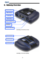
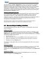
5. Gateway Overview
EtherCAT RUN LED
USB connector
Port 1 (IN)
Port 2 (OUT)
EtherCAT ERROR LED
RS-485 TX
and RX LEDs
Gateway status LED
Gateway Overview (Front)
Power terminals
RS-485 terminals
Chassis ground
Gateway Overview (Back)
13
ICC
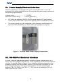
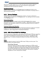
5.1 Power Supply Electrical Interface
When the gateway is not plugged into a PC via the USB cable, it must be
powered by an external power source. Ensure that the power supply adheres to
the following specifications:
Voltage rating ........................ 7 - 24VDC
Minimum Current rating.......... 150mA (@24VDC)
•
ICC offers an optional 120VAC/12VDC power supply (ICC part number
10755) that can be used to power the gateway from a standard wall outlet.
•
The power supply must be connected to the gateway’s terminal block at
terminals TB:5 (POWER) and TB:6 (GND) as highlighted in Figure 1.
Figure 1: Terminal Block Power Supply Connections
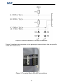
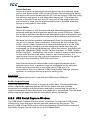
5.2 RS-485 Port Electrical Interface
In order to ensure appropriate network conditions (signal voltage levels, etc.)
when using the gateway’s RS-485 port, some knowledge of the network interface
circuitry is required. Refer to Figure 2 for a simplified network schematic of the
gateway’s internal RS-485 interface circuitry. The port has 4 terminals for fourwire communication. For two-wire communication, connect a jumper wire
between TB:1 (A / RXD+) and TB:3 (Y / TXD+) and a wire between TB:2 (B /
RXD-) and TB:4 (Z / TXD-).
14
ICC
Figure 2: RS-485 Interface Circuitry Schematic
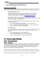
Figure 3 highlights the terminals on the gateway’s terminal block that are specific
to RS-485 connections.
Figure 3: Terminal Block RS-485 Connections
15
ICC
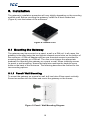
6. Installation
The gateway’s installation procedure will vary slightly depending on the mounting
method used. Before mounting the gateway, install the 4 black rubber feet
(Figure 4) onto the bottom of the enclosure.
Figure 4: Rubber Feet
6.1 Mounting the Gateway
The gateway may be mounted on a panel, a wall or a DIN rail. In all cases, the
gateway is mounted using the two keyhole-shaped screw holes on the bottom of
the enclosure. A DIN rail adapter with two pre-mounted screws is provided for
mounting the gateway on a DIN rail. The user must choose the appropriate
hardware for mounting the gateway on a panel or wall. When choosing screws
for panel or wall mounting, ensure the head size matches the keyhole screw
holes on the back of the enclosure. The following describes the method for the
two mounting options.
6.1.1 Panel / Wall Mounting
To mount the gateway on a panel or wall, drill two holes 25mm apart vertically.
Screw two screws into the holes and mount the gateway on the screws.
Figure 5: Panel / Wall Mounting Diagram
16
ICC
6.1.2 DIN Rail Mounting
The DIN rail adapter (Figure 6) can clip onto 35mm and G-type rails. To mount
the gateway to a DIN rail, clip the DIN rail adapter onto the DIN rail and mount
the gateway on the screws (the screws should already be seated into the adapter
at the proper height). Refer to Figure 7, Figure 8, and Figure 9.
Figure 6: DIN Rail Adapter
Figure 7: DIN Rail Adapter Attachment
Figure 9: Example Installation
Figure 8: Unit with Attached
DIN Rail Adapter
17
ICC
6.2 Wiring Connections
Note that in order to power the unit, a power supply must also be installed. Refer
to section 5.1 for more information.
1.
Mount the unit via the desired method (refer to section 6.1).
2.
Connect the various networks to their respective plugs/terminal blocks.
Ensure that any wires are fully seated into their respective terminal blocks,
and route the network cables such that they are located well away from any
electrical noise sources, such as adjustable-speed drive input power or
motor wiring. Also take care to route all cables away from any sharp edges
or positions where they may be pinched.
3.
Take a moment to verify that the gateway and all network cables have
sufficient clearance from electrical noise sources such as drives, motors, or
power-carrying electrical wiring.
4.
Connect the power supply to the gateway’s RS-485 terminal block on the
terminals labeled POWER and GND. Pay particular attention to the proper
polarity.
6.3 Grounding
Grounding is of particular importance for reliable, stable operation.
Communication system characteristics may vary from system to system,
depending on the system environment and grounding method used.
The gateway has one logic ground located on the RS-485 terminal block, which
serves as the ground reference for both power and RS-485 communication
signals. The gateway is also provided with a chassis ground terminal adjacent to
the RS-485 terminal block. In order to ensure proper EMC behavior, the chassis
ground terminal must be connected to an appropriate ground.
Please be sure to consider the following general points for making proper ground
connections:
Grounding method checkpoints
1.
2.
3.
Make all ground connections such that no ground current flows through the
case or heatsink of a connected electrical device.
Do not connect the chassis GND terminal to a power ground or any other
potential noise-producing ground connection (such as an adjustable-speed
drive’s “E” terminal).
Do not make connections to unstable grounds (paint-coated screw heads,
grounds that are subjected to inductive noise, etc.)
18
ICC
7. LED Indicators
The gateway contains several different LED indicators, each of which conveys
important information about the status of the unit and connected networks. These
LEDs and their functions are summarized here.
7.1 Gateway Status
The gateway has one dichromatic LED to indicate the status of the device. On
startup, the LED blinks a startup sequence: Green, Red, Green, Red. Always
confirm this sequence upon powering the gateway to ensure the device is
functioning properly.
Solid green ............ The status LED lights solid green when the gateway has
power and is functioning normally.
Flashing green ....... The status LED flashes green when the gateway is
connected to a PC via a USB cable.
Flashing red........... If a fatal error occurs, the status LED will flash a red error
code. The number of sequential blinks (followed by 2
seconds of OFF time) indicates the error code.
7.2 RS-485 Network Status
The gateway has one red and one green LED to indicate the status of the RS485 network.
Green (TX) LED ..... Lights when the gateway is transmitting data on the RS-485
port.
Red (RX) LED........ Lights when the gateway is receiving data on the RS-485
port. Note that this does not indicate the validity of the data
with respect to a particular protocol: only that data exists and
is being detected. Also note that if a 2-wire RS-485 network
is in use, that the gateway’s RX LED will light in conjunction
with the TX LED (as transmitting devices on 2-wire RS-485
networks also receive their own transmissions).
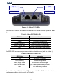
7.3 EtherCAT LEDs
The EtherCAT network has one dichromatic RUN LED and one dichromatic ERR
LED situated on either side of the RJ-45 network port connectors. Each network
port also contains a link/activity LED. Refer to Figure 10.
19
ICC
Port 1
Link/Activity
Port 2
Link/Activity
RUN LED
ERR LED
Figure 10: EtherCAT LEDs
The RUN LED reflects the status of the EtherCAT state machine (refer to Table
1).
Table 1: EtherCAT RUN LED
LED State
Indication
Off
INIT state / no power
Green
OPERATIONAL state
Green, blinking
PRE-OPERATIONAL state
Green, single flash
SAFE-OPERATIONAL state
Red
EXCEPTION state (fatal event)
The ERR LED indicates any communication-related errors (refer to Table 2).
Table 2: EtherCAT ERR LED
LED State
Indication
Off
No error / no power
Red, blinking
Invalid configuration
Red, single flash
Unsolicited state change
Red, double flash
Sync manager watchdog timeout
Red
PDI watchdog timeout
The port 1 and port 2 link/activity LEDs indicate the EtherCAT network link status
and communication activity (refer to Table 3).
20
ICC
Table 3: EtherCAT Link/Activity LED
LED State
Indication
Off
No link / no power
Green
Link sensed, no activity
Green, flickering
Link sensed, activity detected
21
ICC
8. Configuration Concepts
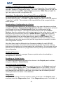
8.1 ICC Configuration Studio
The gateway can be configured by a PC via a USB mini type-B cable. This
connection provides power to the device, so there is no need for any external
power supply while the gateway is attached to the PC.
The gateway is configured by the ICC Configuration Studio PC application, and
this section will provide only a brief introduction to the configuration concepts. For
more detailed information on how to install and use the Configuration Studio,
refer to the separately-available training resources.
Offline Device Configuration
A device can be added to the Project panel for offline configuration by first
selecting the Offline Devices list heading and then:
•
Double-clicking on it in the Available Devices panel.
•
Right-clicking on it in the Available Devices panel and choosing Add from
the context-sensitive menu.
•
Hitting the <ENTER> key on the keyboard when the device is selected in the
Available Devices panel.
•
Dragging it from the Available Devices panel into the Project panel.
The device will then be added to the list of Offline Devices. A valid offline
configuration can be downloaded to a compatible online device at any time.
Online Device Configuration
All connected devices are automatically loaded and added to the list of Online
Devices. When a device is disconnected, its configuration is moved to the list of
Offline Devices.
Removing an Offline Device from a Project
An offline device can be removed from a project by:
•
Selecting the device in the Project panel and dragging it. A trash can icon
will appear at the bottom of the Project panel, and dragging the device to
the trash will then delete it from the project.
•
Hitting the <DELETE> key on the keyboard when the device is selected in
the Project panel.
•
Right-clicking on the device in the Project panel and choosing Remove from
the context-sensitive menu.
•
Selecting Remove Selected Item from the Edit menu when the device is
selected.
•
Clicking on the Remove button in the toolbar when the device is selected.
22
ICC
Loading a Configuration from an XML File
This feature is intended to support the import of configuration files created with
the older Gateway Configuration Utility. To load a configuration from an XML file
stored on the PC, click File…Open Project, select the “XML Files (*.xml)” file
type, and open the XML configuration file.
Importing a Configuration from a Project File or an XML File
An existing project file or configuration XML file can be imported into the
currently-active project. Click File…Import Project, and then select the desired
*.icsproj or *.xml file. The contents of the imported file will be merged with the
active project.
Downloading a Configuration to a Device
To download a configuration to an online device, first select the device and then
navigate to Device…Download Configuration to Device. If the device selected
was already in the list of Online Devices, then the configuration will be
downloaded to this device. If the device selected was in the list of Offline
Devices, then the configuration will be downloaded to the online device, and the
device will be removed from the list of Offline Devices. Note that to prevent
ambiguity with respect to which online device is being targeted, the studio will
allow downloading from an offline device only when a single instance of a
compatible device is online: if multiple compatible devices are currently online,
then disconnect all other devices until just the target device intended to receive
the configuration remains.
Note that there may be different driver firmware available for each RS-485
protocol. If necessary, the studio will automatically update the device with the
appropriate firmware prior to downloading the configuration. Do not power off the
device once the download is in progress as this may corrupt the firmware and/or
the configuration.
Updating Firmware
The studio automatically manages firmware updates when downloading a
configuration to a device.
Resetting an Online Device
To reset an online device, first select the device in the Project panel and then
navigate to Device…Reset Device.
Interacting with the Database
To interact with a device’s database, select the device in the Project panel and
then select the Database panel. If the Database panel is not visible, it can be
enabled via View…Database. When an online device is selected, data values
are updated from the device in real-time, and values can be edited by doubleclicking the desired location in the database.
Diagnostics
To monitor the status of service objects, select the device in the Project panel
and then select the Diagnostics panel. If the Diagnostics panel is not visible, it
23
ICC
can be enabled via View…Diagnostics. When an online device is selected,
diagnostics information is updated from the device in real-time. Individual
diagnostics objects can be selected by clicking on them in the list, and multiple
items can be selected by either <CTRL>+clicking on them (to select them
individually) or <SHIFT>+clicking on them (to select a range of items). Counter
values of all currently-selected diagnostics objects can be reset by clicking the
Reset Selected Counters button.
General Configuration Process
To configure a device, add the desired protocols for the various ports, configure
the communication settings (baud rate, parity, address, timeout, and scan
rate/response delay etc.), and configure any objects associated with the
respective protocols. Regardless of whether configuration changes are made to
an online or offline device, those changes will only take effect once the
configuration is downloaded to a device.
Note that numeric values can be entered not only in decimal but also in
hexadecimal by including “0x” before the hexadecimal number.
8.2 General Object Editing Activities
The following editing activities apply for all types of configuration objects and
project elements.
Adding an Object
To add an object, click on an item (protocol driver or Node, for example) in the
Project panel. Any available objects for that item will be listed in the Available
Objects panel (the panel title depends on the currently-selected item). An object
can then be added to the item by:
•
Double-clicking on it.
•
Right-clicking on it and choosing Add from the context-sensitive menu.
•
Hitting the <ENTER> key on the keyboard when the object is selected.
•
Dragging it into the Project panel.
The object’s configurable fields can then be populated with valid values (where
applicable).
Viewing an Object
In the Project panel, select a parent object to display a summary of all its child
objects. For example, selecting a protocol driver will display the driver’s
configuration in the Summary panel and list of current objects in the Object List
panel.
Updating an Object
To update an object, select the object in the Project panel and make any
required changes in the Settings panel.
24
ICC
Deleting an Object
An object can be deleted by performing one of the three following actions:
•
Selecting the object in the Project panel and dragging it. A trash can icon
will appear at the bottom of the Project panel, and dragging the object to the
trash will then delete it from the project.
•
Hitting the <DELETE> key on the keyboard when the object is selected in
the Project panel.
•
Right-clicking on the object in the Project panel and choosing Remove from
the context-sensitive menu.
•
Selecting Remove Selected Item from the Edit menu when the object is
selected.
•
Clicking on the Remove button in the toolbar when the object is selected.
Note that this action cannot be undone. Deleting an object will also delete all of
its child objects.
Copying and Pasting an Object
To copy an object, first click on an item in the Project panel. An object can then
be copied by:
•
Right-clicking on it and choosing Copy from the context-sensitive menu.
•
Pressing the <CTRL+C> keys on the keyboard.
•
Holding the <CTRL> key and dragging the item to the desired location in the
Project panel.
•
Dragging the item to a new location under a different parent object in the
Project panel.
•
Selecting Copy Selected Item from the Edit menu.
•
Clicking on the Copy button in the toolbar.
To paste an object, first click on an item at the desired location in the Project
panel. An object can then be pasted by:
•
Right-clicking on it and choosing Paste from the context-sensitive menu.
•
Pressing the <CTRL+V> keys on the keyboard.
•
Dropping an item onto the desired location in the Project panel after holding
the <CTRL> key and dragging the item.
•
Dropping an item onto a new location under a different parent object in the
Project panel after dragging the item.
•
Selecting Paste Item from the Edit menu.
•
Clicking on the Paste button in the toolbar.
After pasting an object, the object’s configurable fields can then be modified with
valid values (where applicable).
25
ICC
Note that the studio allows you to copy and paste items between different
locations, including different devices. This is useful for copying partial
configurations from one device to another.
Reordering Objects
Objects can be reordered in the Project panel by dragging the item to the
desired location. If the item is dragged outside of the items in the project tree, it
will be moved to the end.
8.2.1 Device Settings
The following fields can be configured for a device. To view or edit device
settings, click on the device in the Project panel. The settings are then available
in the Settings panel.
Device Description
Each device added to a project can be individually tagged with a unique
description string of up to 32 characters in length. This allows the devices within
a project or an automation system to be clearly identifiable with their location or
functional purpose.
Database Endianness Selection
Select the desired endianness for how data will be stored in the device’s internal
database for multi-byte data types. For more information on database
endianness, refer to Appendix A: Database Endianness.
8.2.2 USB Virtual COM Port Settings
The device can be configured to enumerate as a USB virtual COM port, providing
direct serial communications between the device and a PC through the USB
connection. The COM port can be used for various tasks, depending on the
selected mode. This section details the different functions of the virtual COM
port.
Mode
Select the desired mode for how the USB virtual COM port will be used. The
available options are detailed below.
Serial Pass-Through
Select this option to cause the device to behave as a USB-to-serial
converter. Any data sent to the USB virtual COM port will be forwarded
to the physical serial port and any data received by the physical serial
port will be forwarded to the USB virtual COM port. Note that while the
device is in this mode all other functionality of the device is disabled,
regardless of other configuration settings.
26
ICC
Serial Redirect
Select this option to redirect communications from the selected serial
port on the device to the USB virtual COM port. By selecting this option,
the device will communicate with the PC over the virtual COM port using
the settings configured on the associated serial port. This allows the
device to communicate with the PC using any of the supported serial
port protocols. Note that the physical serial port is disabled when the
device is configured in this mode.
Serial Sniffer
Select this option to sniff the received and transmitted packets on the
selected serial port and output the data to the virtual COM port. When
this mode is selected, the device will attempt to output every packet that
the protocol driver configured on the serial port receives and transmits.
Because the sniffer operates independently from the physical serial port
(so as not to impact communications), there may be times when the
sniffer cannot output a received or transmitted packet due to the USB
connection being unable to process characters faster than they are
exchanged on the physical serial port. When this occurs, the sniffer will
output the characters "ERR: Sniffer Packet Overflow" or "ERR: Sniffer
Buffer Overflow". Additionally, the sniffer is able to detect receive errors
on the serial port such as parity, overrun, and framing errors. If a
receive error occurs on one or more characters of a packet, the sniffer
will output the characters “ERR: Receive Error”.
Note that because the serial sniffer mode captures packets at the
protocol driver level, a protocol must be configured on the selected
serial port to provide data to the USB virtual COM port. For
convenience, there is a special “USB Serial Sniffer Settings” protocol
selection to configure the serial port for sniffing only.
Serial Port
Select the desired serial port to use with the USB virtual COM port.
Sniffer Output Format
Select the desired output format of the serial sniffer data. The formatted data
option outputs the captured data as ASCII text characters and includes
annotations for whether the packet was received or transmitted, as well as a
relative timestamp of when the packet was received or transmitted. The raw data
option outputs the captured data as unmodified, binary characters.
8.2.3 USB Serial Capture Window
The USB Serial Capture Window allows connection to a device's USB Virtual
COM port to view and save network packets captured by the device. The
device's USB Virtual COM port must be configured for Serial Sniffer mode and
the Sniffer Output Format must be set to Formatted Data.
27
ICC
When connected, the capture window will display the device’s most recent
received and transmitted packets. All packets captured during the duration of the
session may be saved once the session has ended, even though they all may not
be displayed in the window. The status bar at the bottom of the window tracks
the duration of the connection as well as the total number of packets the device
has received and transmitted.
To open the USB Serial Capture Window, select USB Serial Capture Window…
from the Tools menu.
Capturing Packets
To begin capturing packets, the device must first be configured with the
appropriate USB Virtual COM port settings as described above. Once configured,
the device will appear in the COM Port selection box. Select the desired device
from this drop down and connect to the device. To connect to the device, perform
one of the following actions:
•
Select Connect from the Connection menu.
•
Click on the Connect button in the toolbar.
Note that connecting to a device will clear the capture log automatically.
Clearing the Capture Log
All captured data may be cleared at any time while connected to a device or after
disconnecting from a device. This will also reset the connection time duration and
all counters. To reset all captured data, perform one of the following actions:
•
Select Clear Log from the Edit menu.
•
Click on the Clear Log button in the toolbar.
•
Hit the <DELETE> key on the keyboard.
•
Right click on the capture output and select Clear Log.
Pausing the Display
While capturing, the output window will display only the most recent packets.
Therefore, as new packets are captured and displayed in the window, old
packets are removed from the display. At any time during capturing, the display
updating may be paused so that no packets are added or removed. To pause the
display, perform one of the following actions:
•
Select Pause Display from the Display menu.
•
Click on the Pause Display button in the toolbar.
•
Right click on the capture output and select Pause Display.
Note that even though the display does not update when paused, packets are
still being captured in the background.
Ending a Capture Session
The capture session is ended by disconnecting from the selected device. To
disconnect from the device, perform one of the following actions:
28
ICC
•
Select Disconnect from the Connection menu.
•
Click on the Disconnect button in the toolbar.
Saving the Captured Data
Once a capture session has ended, the entire captured data may be saved. The
data can be saved either as a Wireshark capture file or as a plain text document.
Wireshark Capture File
The captured data can be saved as a file which can be opened,
decoded, and analyzed by Wireshark. Wireshark is a free network
protocol analyzer and is available at http://www.wireshark.org/.
Any protocol capture may be viewed with Wireshark. However,
Wireshark currently only supports decoding BACnet MS/TP packets and
has limited support for Modbus RTU.
To save the captured data as a Wireshark capture file, perform one of
the following actions:
•
Select Save As Wireshark Capture… from the File menu.
•
Click on the Save As Wireshark Capture… button in the toolbar.
•
Hit the <CTRL+S> keys on the keyboard.
Text Document
The captured data can also be saved as a plain text document. To save
the captured data as a text document, perform one of the following
actions:
•
Select Save As Text… from the File menu.
•
Click on the Save As Text… button in the toolbar.
•
Hit the <CTRL+SHIFT+S> keys on the keyboard.
8.3 Internal Logic Settings
8.3.1 Fail-safe Values
8.3.1.1 Overview
The gateway can be configured to perform a specific set of actions when network
communications are lost. This allows each address in the database to have its
own unique “fail-safe” condition in the event of network interruption. Support for
this feature varies depending on the protocol: refer to the protocol-specific
section of this manual for further information.
Note that this timeout feature is only used with slave/server protocols: this is not
the same as the Timeout time used for service objects in master/client protocols.
There are two separate elements that comprise the timeout configuration:
29
ICC
•
The timeout time
•
Timeout Object configuration
8.3.1.2 Timeout Time
The timeout time is the maximum number of milliseconds for a break in network
communications before a timeout will be triggered. This timeout setting is
configured at the protocol level as part of a driver’s configuration, and used by
the protocol drivers themselves to determine abnormal loss-of-communications
conditions. These conditions then trigger gateway-wide timeout processing
events. If it is not desired to have a certain protocol trigger timeout processing
events, then the protocol’s timeout time may be set to 0 (the default value) to
disable this feature.
For some protocols, the timeout time is set by the master device (PLC, scanner,
etc.), and a timeout time setting is therefore not provided in the Configuration
Studio’s driver configuration. Additionally, not all protocols support timeout
detection: refer to the protocol-specific sections of this manual for more
information.
8.3.1.3 Timeout Object Configuration
A timeout object is used by the gateway as part of the timeout processing to set
certain addresses of the database to “fail-safe” values. When a timeout event is
triggered by a protocol, the timeout objects are parsed and the designated 8-bit,
16-bit, or 32-bit value is written to the corresponding database address(es). To
add a timeout object to a device, select the device in the Project panel, then add
Internal Logic…Fail-safe Values…Timeout Object. The following paragraphs
describe the configurable fields of a timeout object:
Database Address
Enter the starting address in the database where the first data element of this
timeout object will begin. The maximum allowable database address depends on
the designated Data Type.
Data Type
The size and range of valid values for each data element in this timeout object.
For instance, selecting “16-Bit Unsigned” allows for a range of timeout values
between 0 and 65535, each occupying 2 bytes in the database. Similarly,
selecting “16-Bit Signed” allows for a range of values between -32768 and
32767, also occupying 2 bytes in the database. Select the desired data type from
this dropdown.
Value
Enter the “fail-safe” timeout value that each database address encompassed by
this timeout object will be automatically written with upon processing a timeout
event triggered by a protocol.
30
ICC
Length
Enter the number of data elements for this timeout object. The total number of
database bytes modified by a timeout object is determined by the Length
multiplied by the number of bytes in the selected Data Type (1, 2 or 4 for 8-bit,
16-bit and 32-bit, respectively).
8.3.2 Database Logic
8.3.2.1 Overview
A variety of database logic operations are included which provide PLC-style
manipulation of database values. Categories such as logical, arithmetic and
filtering operations allow for autonomous control over value modification and data
movement within the database. High-level signal conditioning is also realizable
via the construction of compound formulas derived from the elemental building
block operations provided. To add database logic operations to a device, select
the device in the Project panel, then add Internal Logic…Database Logic.
Database logic operations are executed in sequential order, according to the
ordinal position in which the operations are listed in the Project panel under the
Database Logic heading.
Some notes of interest for the database logic operations are as follows:
All Database Logic Operations
•
All inputs to an operation may either be a value located in the internal
database or a constant value.
•
A floating-point “Multiplier” field is available on each database-sourced input
and on the output which allows the inputs to be scaled prior to operation
execution, and the result to be scaled after operation execution. The input is
multiplied by the input multiplier, and the result is divided by the output
multiplier.
•
All operations can be dynamically enabled/disabled using an optional
“Enable Trigger” element (refer to section 8.3.2.3 for more information on
Enable Trigger behavior.)
•
The outputs of all operations must be stored in the internal database.
•
The number of bytes taken from the database (for non-constant inputs) is
determined by the corresponding “Data Type” selection, starting at the
designated “Database Address”.
•
The number of bytes written to the database (for outputs) is determined by
the corresponding “Data Type” selection, starting at the designated
“Database Address”.
Logical Operations
•
Not, And, Or, and Exclusive Or operations can be performed on either a
bitwise or logical basis, depending on the selection of the “Operation Type”.
When a logical operation type is chosen, non-zero input values are
considered to be “true” and zero input values are considered to be “false”.
31
ICC
The output value of the logical operation will then be written to the database
as “1” for true and “0” for false.
•
The Copy operation outputs the input value.
•
The Bit Copy operation outputs the value of a single bit from the input
database location to a single bit in the output database location. No other
bits in the output database location are modified by this operation.
•
The Indirect Copy operation outputs the value at the database location
specified by the input source to the database location specified by the output
destination. This operation can be used to access different database
locations dynamically. It could also be used to create reusable database
logic subroutines by selecting a different input and output location for the
subroutine during each execution cycle.
•
The Shift operation outputs the input value bit-shifted by the shift amount.
•
The Compare operation outputs a “1” if the comparison evaluates to true,
otherwise it outputs a “0”.
•
The Flag Test & Set operation tests if the bit flags specified in the input mask
are set in the input value and sets the bit flags specified in the output mask
in the output value. This operation can test for ALL flags set/cleared or ANY
flags set/cleared. If the flag test evaluates as true, all bit flags specified in the
output mask in the output value are set, otherwise the flags are cleared.
Only the bits specified in the output mask in the output value are modified by
this operation.
•
The Value Change Detection operation outputs a “1” if a change is detected
in the input value between the last execution cycle and the current execution
cycle, otherwise it outputs a “0”.
•
The Mutiplexer operation outputs one of its two inputs, depending on the
selection. If Selection is zero, Input 1 is output. If Selection is non-zero, Input
2 is output.
•
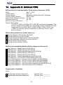
The Byte Reverse operation reverses the byte order of the input value and
outputs the result.
Arithmetic Operations
•
The Add operation calculates the expression [Input 1] + [Input 2].
•
The Subtract operation calculates the expression [Input 1] – [Input 2].
•
The Multiply operation calculates the expression [Input 1] × [Input 2].
•
The Divide operation calculates the expression [Input 1] / [Input 2].
•
The Modulo operation calculates the expression [Input 1] mod [Input 2].
•
. “Input
The Exponential operation calculates the expression [Input 1]
1” can be a database value, a constant value, or e (exponential function).
•
The Nth Root operation calculates the expression
•
The Logarithm operation calculates the expression logBase(Input 1). “Base”
can be a database value, a constant value or e (natural logarithm).
•
The Random operation outputs a random number between Input 1 and Input
2. Note that the operation is limited to producing only 32,768 unique values.
Exponent
32
Degree
�Input 1.
ICC
•
The Divide, Exponential, Nth Root and Logarithm operations output an
integer-rounded value when an integer data type is used.
Trigonometric Operations
•
The Sine operation calculates the expression sin(Input 1), where Input1 is in
radians.
•
The Cosine operation calculates the expression cos(Input 1), where Input1 is
in radians.
•
The Tangent operation calculates the expression tan(Input 1), where Input1
is in radians.
•
The Arc Sine operation calculates the expression sin (Input 1), where the
output is in radians.
•
The Arc Cosine operation calculates the expression cos (Input 1), where
the output is in radians.
•
The Arc Tangent operation calculates the expression tan (Input 1), where
the output is in radians.
-1
-1
-1
Filtering Operations
•
The Debounce Filter and Hysteresis Filter operations are functionally
identical with the single exception that the Debounce Filter does not use a
“Value Tolerance” (it is fixed at 0).
•
In order for the output of the Debounce Filter or Hysteresis Filter to change
(i.e. reflect the input value), “Input 1” must first change to a value outside of
the “Value Tolerance” range and then must remain within the “Value
Tolerance” range of the new value for the entire “Stable Time”.
8.3.2.2 Database Logic Settings
Scan Rate
Defines the scan cycle time in milliseconds (50ms minimum) of the database
logic processing task. All operations are evaluated for execution in sequential
order at this frequency. Note that this does not necessarily mean that each
operation is guaranteed to execute every scan cycle: only that it will be evaluated
as to whether or not it should execute. Namely, if an “Enable Trigger” element is
added to an operation, then the trigger must evaluate to “true” for the operation to
execute during that scan cycle. Refer to section 8.3.2.3 for more information on
Enable Trigger behavior.
8.3.2.3 Enable Trigger
Each database logic operation can optionally include an “Enable Trigger”
element, which provides dynamic conditional execution capabilities. By default
(i.e. if an enable trigger element is not added to the operation), each operation is
automatically triggered to execute every scan cycle. If it is desired for an
operation to execute conditionally, however, then an enable trigger element can
be added to it. The enable trigger element defines an “Enable Value”, which
specifies a byte-size trigger value that can reside at any location in the internal
database. When implemented, the enable value is evaluated every scan cycle: if
33
ICC
this value is non-zero (or zero when the “Inverted” Trigger Option is used), the
operation will execute.
The enable value itself can be modified by any communication driver currently
running on the device, which enables networked devices to dynamically control
the execution of database logic operations. The enable value can also be the
output result of other database logic operations. While the output of any
database operation can be used for this purpose, such a scenario may most
typically use the output of a “compare” operation in order to control whether or
not other operations should execute (e.g. execute a certain operation only when
some process variable is greater than a certain value, etc.) Allowing the
conditional execution of database logic operations to be based on data values
obtained via communications or as a result of other database logic operations
enables the construction of flexible, hierarchical and dynamic data evaluation and
manipulation engines.
Enable Value Database Address
Enter the database address which specifies the byte-size trigger value.
8.3.2.3.1.1
Trigger Options
The enable trigger can perform basic logic on the enable value to determine if an
operation should execute using a variety of trigger options. These setting
determine what logic should be applied to the enable value when evaluating
whether or not the operation should execute.
Inverted
Specifies whether the enable logic should be inverted. This applies to both the
evaluation of whether or not the operation should execute as well as resetting the
enable value when the auto reset option is used.
Auto Reset
Allows the enable value to be automatically reset upon completion of the
operation. The actual value written to the enable value depends on the other
trigger options selected. If no options are selected, a value of 0 is written to the
enable value. If the inverted option is used, a value of 1 is written to the enable
value. If the bitmask option is used, each bit selected in the bitmask is written to
a 0 (or a 1 if the inverted option is used) in the enable value.
Bitmask
If this option is used, it selects which bits in the enable value to evaluate. Every
selected bit in the enable value must be 1 (or 0 when the inverted option is used)
for the operation to execute.
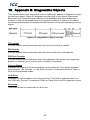
8.4 Service Objects and Diagnostics Objects
A service object is used by the gateway to make requests on a network when a
master/client protocol is enabled. Each service object defines the services (read
34
ICC
and/or write) that should be performed on a range of network objects of a
common type. The data from read requests is mirrored in the database starting at
a user-defined address (if a read function is enabled). When a value within that
address range in the database changes, a write request is generated on the
network (if a write function is enabled). Specific service object configuration
depends on the protocol selected: refer to the protocol-specific section of this
manual for further details.
Master/client drivers commonly also provide the ability to debug configured
service objects while the driver is running by way of optional diagnostics objects.
Where supported, diagnostics objects can be added to each service object, and
a database address can be designated at which to store the status information.
The diagnostics object is a 16-byte structure containing elements such as a
transmission counter, receive counter, receive error counter, current status, and
the last error of the defined service object. This information is detailed in
Appendix B: Diagnostics Objects. Because the diagnostics object resides in the
database alongside the service object’s process data, it can also be accessed
over any supported network by mapping appropriate network elements to the
corresponding database addresses.
Alternatively, the diagnostics objects can be viewed within the Configuration
Studio by selecting a device in the Project panel and then either clicking on or
hovering over the Diagnostics panel. Diagnostics objects are automatically
added to the Diagnostics panel, and are disseminated and displayed in plain
text for easy interpretation. For online devices, diagnostics objects are updated in
real-time and all counters can be reset by selecting one or more entries in the list
and clicking the Reset Selected Counters button.
35
ICC
9. RS-485 Drivers
The gateway supports a variety of serial drivers on its RS-485 port. For a list of
supported protocols, refer to the Millennium Series Supported Drivers List. For
detailed information on each protocol, refer to the specific protocol’s driver
manual.
36
ICC
10. EtherCAT Driver
For detailed information on the EtherCAT protocol driver, refer to the separate
EtherCAT protocol driver manual.
37
ICC
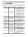
11. Troubleshooting
Although by no means exhaustive, the following table provides possible causes
behind some of the most common errors experienced when using the gateway.
Problem
Symptom
Solution
•
•
The gateway will
not turn on
All LEDs are off and
the gateway shows
no activity
No
communication
between the RS485 network and
the gateway
The gateway’s RS485 TX and RX LEDs
are blinking slowly,
sporadically, or not at
all
No
communication
between the RS485 network and
the gateway
The gateway’s RS485 RX LED is solid
ON
No
communication
between the
EtherCAT
network and the
gateway
The gateway’s
EtherCAT RUN LED
is flashing green or
off and the ERR LED
is flashing red or off
•
•
Firmwaregenerated error
•
•
•
•
The module status
LED is flashing red:
the number of times
the LED flashes
indicates an error
code
38
•
Confirm that power is connected
to the correct inputs on the RS485 terminal block.
If powering over USB, ensure the
USB cable from the kit is used,
and that the computer is able to
supply sufficient power as a USB
host device.
If firmware was being updated, it
may have been corrupted.
Unplug and reconnect the USB
cable and run the Configuration
Studio. Follow the Configuration
Studio instructions to restore the
firmware.
Check connections and
orientation of wiring between the
network and the gateway.
Confirm that the protocol, baud
rate, parity, and address settings
on the RS-485 port match your
network configuration.
The RS-485 signal wires are
reversed.
Ensure that a network
reference/ground wire is in place.
Check connections and
orientation of wiring between the
network and the gateway.
Confirm that the address and
size settings on the EtherCAT
port match your network
configuration.
•
6 flashes indicate the gateway is
in USB to Serial Pass-Through
mode. All other functionality of
•
Any other number of flashes
indicates an internal device error.
Record the blink sequence and
contact ICC for further
assistance.
the device is disabled.
ICC
Problem
Symptom
Solution
The device will
not communicate
to the
Configuration
Studio via USB
The USB cable is
plugged into both the
PC and the device,
but the module status
LED is not flashing
green: the
Configuration Studio
may indicate a
communication error
39
•
•
•
•
•
Unplug and reconnect the USB
cable.
Try a different USB cable.
Try a different USB port on the
computer.
Reinstall the Configuration
Studio.
Reinstall the USB device drivers
(contact ICC for assistance).
ICC
12. Appendix A: Database Endianness
A key feature of the Millennium Series gateways is the ability to change the byte
order storage scheme for data in the database between big endian and little
endian. The database endianness is the convention used to store multi-byte data
to or retrieve multi-byte data from the database. The selected endianness affects
the end-to-end consistency of multi-byte data between the two networks on the
gateway.
To better understand how this byte-ordering scheme works, the following
explains how the gateway stores and retrieves multi-byte data to and from the
database. Data is stored into the database starting at the low address and filled
to higher addresses. The endianness determines whether the most-significant or
least-significant bytes are stored first.
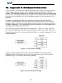
Let’s look at some examples that demonstrate this. Figure 11 shows how the
hex value 0x12345678 is stored into the database using a big endian byte order.
Since the hex value 12 is the most significant byte, it is stored at address “a”, the
lowest address.
Figure 11: Big Endian Storage
Figure 12 demonstrates how the hex value 0x12345678 is stored into the
database using a little endian byte order. Since the hex value 78 is the least
significant byte, it is stored at the lowest address.
Figure 12: Little Endian Storage
40
ICC
Similarly, data is retrieved from the database starting at the low address. The
endianness decides whether the first byte is interpreted as the least-significant
byte or the most-significant byte of the multi-byte number.
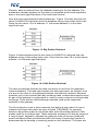
Here are some examples that demonstrate this. Figure 13 shows how the hex
value 0x12345678 is retrieved from the database using a big endian byte order.
Since the hex value 12 is at address “a”, the lowest address, it is the most
significant byte.
Figure 13: Big Endian Retrieval
Figure 14 demonstrates how the hex value 0x12345678 is retrieved from the
database using a little endian byte order. Since the hex value 78 is at the lowest
address, it is the least significant byte.
Figure 14: Little Endian Retrieval
The above examples illustrate the data movement to and from the gateway’s
internal database. This idea helps explain the data movement, as a whole, from
one port to the other on the gateway between two different networks. Because
networks vary in the manner that they exchange data, endianness selection must
be part of the gateway’s configuration in order to ensure coherent multi-byte data
exchange. There are two data exchange methods used by the supported
networks of the gateway.
The first method is used in those networks that define a byte order for how to
interpret multi-byte data within an array of bytes. PROFIBUS, for example,
defines a big-endian order for multi-byte data, while DeviceNet defines a littleendian order for multi-byte data. These networks exchange I/O data by means of
a “bag of bytes” approach, whereas the gateway need not concern itself with
where individual values are delimited within the array of bytes itself (as this is
determined by the sending or receiving nodes on the networks). The bytes are
41
ICC
simply stored into the database in the order they were received. Gateway
endianness selection therefore has no effect on data storage or retrieval with a
“bag of bytes” protocol driver.
The other method is that used by networks that exchange data by means of an
“object value” system, whereas data is exchanged by addressing a certain object
to read or write data. Modbus for example, uses registers, while BACnet uses
objects such as analog values to exchange data. When multi-byte values are
received by the gateway, the bytes must be stored into the database in the order
defined by the endianness selected. Likewise, when retrieving multi-byte values
from the database for the gateway to transmit, the endianness selected will
determine how the data is reconstructed when read from the database.
The selection of the correct byte ordering is crucial for coherent interaction
between these two types of networks on the gateway. The following presents
examples of how the database endianness affects end-to-end communication
between networks and when each byte-ordering scheme should be used.
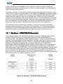
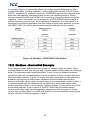
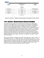
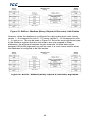
12.1 Modbus - PROFIBUS Example
This example shows the interaction between a network using an object value
method (Modbus) and one using a bag of bytes method (PROFIBUS) to
exchange data. The gateway reads holding registers 1 and 2 from the Modbus
network, stores the data into the database, and then sends the 4 bytes of input
data onto the PROFIBUS network. Figure 15 shows this data movement for the
gateway’s database configured as big endian. Because the PROFIBUS
specification defines multi-byte values within the byte array to be interpreted as
big endian, it is recommended that the database be configured for big-endian
byte order when using PROFIBUS. In the example, holding register 1 has a value
of 0x1234 and holding register 2 has a value of 0x5678. When the PROFIBUS
device receiving the input data from the gateway recombines the two pairs of 2byte values, the resulting data is 0x1234 and 0x5678, thus successfully receiving
the correct values for holding registers 1 and 2.
Figure 15: Modbus - PROFIBUS Big Endian
42
ICC
In contrast, Figure 16 shows the effects of configuring the database for littleendian byte order. Holding registers 1 and 2 again have values of 0x1234 and
0x5678, respectively. However, when the PROFIBUS device receiving the input
data from the gateway interprets these values, the resulting pairs of 2-byte
values become 0x3412 and 0x7856, thus receiving incorrect values for holding
registers 1 and 2. Note that in both examples, the PROFIBUS network data is
always identical, byte-for-byte, to the gateway’s database. For this reason it is
important to configure gateways that use a bag-of-bytes style network, such as
the PBDP-1000, to use the same endianness as defined for that network.
Figure 16: Modbus - PROFIBUS Little Endian
12.2 Modbus - DeviceNet Example
This example shows the interaction between a network using an object value
method (Modbus) and one using a bag of bytes method (DeviceNet) to exchange
data. The gateway reads holding registers 1 and 2 from the Modbus network,
stores the data into the database, and then sends the 4 bytes of input data onto
the DeviceNet network. Figure 17 shows this data movement for the gateway’s
database configured as little endian. Because the DeviceNet specification
defines multi-byte values within the byte array to be interpreted as little endian, it
is recommended that the database be configured for little-endian byte order
when using DeviceNet. In the example, holding register 1 has a value of 0x1234
and holding register 2 has a value of 0x5678. When the DeviceNet device
receiving the input data from the gateway recombines the two pairs of 2-byte
values, the resulting data is 0x1234 and 0x5678, thus successfully receiving the
correct values for holding registers 1 and 2.
43
ICC
Figure 17: Modbus - DeviceNet Little Endian
In contrast, Figure 18 shows the effects of configuring the database for bigendian byte order. Holding registers 1 and 2 again have values of 0x1234 and
0x5678, respectively. However, when the DeviceNet device receiving the input
data from the gateway interprets these values, the resulting pairs of 2-byte
values become 0x3412 and 0x7856, thus receiving incorrect values for holding
registers 1 and 2. Note that in both examples, the DeviceNet network data is
always identical, byte-for-byte, to the gateway’s database. For this reason it is
important to configure gateways that use a bag-of-bytes style network, such as
the DNET-1000, to use the same endianness as defined for that network.
Figure 18: Modbus - DeviceNet Big Endian
12.3 BACnet - DeviceNet Example
This example is quite similar to the previous one as data is exchanged between
an object-value style network (BACnet) and a bag-of-bytes style network
(DeviceNet). The key difference is that in this example, BACnet Analog Value 0
is a 32-bit value, as opposed to two 16-bit Modbus registers. Here, the gateway
44
ICC
reads analog value 0 from the BACnet network, stores the data into the
database, and sends the input data onto the DeviceNet network. Figure 19
demonstrates the data flow from the BACnet network to the DeviceNet network
through a gateway configured to use a little endian database. Because the
DeviceNet specification defines multi-byte values within the byte array to be
interpreted as little endian, it is recommended that the database be configured for
little-endian byte order when using DeviceNet. In the example, analog value 0
has a value of 0x12345678. When the DeviceNet device receiving the input data
from the gateway interprets the 4 bytes, the resulting 4-byte value will be
0x12345678, thus successfully receiving the original value of the BACnet analog
value object.
Figure 19: BACnet - DeviceNet Little Endian
Conversely, Figure 20 illustrates the consequences of configuring the database
for big-endian byte order using this scenario. Once again, Analog Value 0 has a
value of 0x12345678. But now, when the DeviceNet device interprets the 4 bytes
of input data sent by the gateway, the resulting 4-byte value is 0x78563412, thus
receiving an incorrect value for Analog Value 0. Note that in this example as well,
the DeviceNet byte array is identical, byte-for-byte to the database. This
example, in conjunction with the previous, demonstrates the dependence on the
bag-of-bytes style networks for correct database endianness selection.
45
ICC
Figure 20: BACnet - DeviceNet Big Endian
12.4 BACnet - Modbus Analog Element Example
This example exhibits two networks that both use an object value scheme to
exchange data. In this scenario, the database endianness is irrelevant if the data
types are the same for both networks. This example shows communication
between a BACnet network and a Modbus network using two 16-bit analog value
BACnet objects and two 16-bit Modbus holding registers. As shown in Figure 21,
the values from the BACnet network are stored into the database with big-endian
byte ordering. Figure 22 shows the values from the BACnet network being stored
into the database with little-endian byte ordering. Regardless of the byte-ordering
scheme used, the two holding registers on the Modbus network receive the same
values. Notice that in both cases, analog values 1 and 2 have values of 0x1234
and 0x5678, respectively, while holding registers 1 and 2 also have values of
0x1234 and 0x5678, respectively. The only difference between the two cases is
how the data is being stored internally on the gateway itself.
Figure 21: BACnet - Modbus (Analog Objects & Registers) Big Endian
46
ICC
Figure 22: BACnet - Modbus (Analog Objects & Registers) Little Endian
12.5 BACnet - Modbus Binary Element Example
This example also contains two networks that both employ an object value
method for exchanging data, but unlike the previous example, the database
endianness does affect the end-to-end alignment of the data. In this example,
communication is taking place between a BACnet network and a Modbus
network using single-bit data elements. The BACnet side is using binary values 1
through 32, while the Modbus side is using coil status 1 through 32. The byte
ordering of the database is significant because of the manner in which Modbus
coils are mapped in the gateway. Coils (and input statuses) are mapped to
registers, not addresses (refer to the Modbus driver documentation for more
information). Since registers are 16-bit entities, the byte order of the registers
(and by association, the coils), is affected by the endianness configured for the
database. BACnet binary objects, however, are mapped on a byte-wise basis
into the database.
When the database is configured for a little-endian byte order, binary values 1…8
corresponds to coils 1…8, binary values 9…16 corresponds to coils 9…16, and
so on. This can be seen in Figure 23. Notice that the least significant bytes of the
registers that the coils map to are placed in the lower memory addresses in the
database. Because Modbus discretes are mapped to registers in a bit-wise littleendian fashion, it is recommended that the database be little endian in this
scenario so that bit-wise data will align between networks.
47
ICC
Figure 23: BACnet - Modbus (Binary Objects & Discretes) Little Endian
However, when the database is configured for a big-endian byte order, binary
values 1…8 correspond to coils 9…16, binary values 9…16 correspond to coils
1…8, and so on. This can be seen in Figure 24. Since the most significant bytes
of the Modbus registers that the coils map to are now mapped to lower
addresses, the alignment between the two networks’ bit-wise data is byte
swapped. While this alignment can still be used, it is much more intuitive when
the database is configured to be little endian.
Figure 24: BACnet - Modbus (Binary Objects & Discretes) Big Endian
48
ICC
13. Appendix B: Diagnostics Objects
This section details the information that is enabled by adding a diagnostics object
to a service object. Figure 25 diagrams the structure of this status information.
Because this 16-byte structure resides in the database at a user-designated
location, it can be accessed from any supported network or protocol in order to
continuously determine the health and performance of the corresponding service
object.
Figure 25: Diagnostics Object Format
TX Counter
A 32-bit counter that increments when the driver transmits a packet.
RX Counter
A 32-bit counter that increments when the driver receives a valid packet.
RX Error Counter
A 32-bit counter that increments when the gateway receives an error response
packet, or when an error occurs upon reception of a packet.
Current Status
Indicates the status of the most-recently received packet. This field is updated
each time the “RX Counter” or “RX Error Counter” increments. Refer to Table 4
for a list of supported codes.
Last Error
Indicates the last reception error that occurred. This field is updated each time
the “RX Error Counter” increments. Refer to Table 4 for a list of supported codes.
Reserved
These two bytes are reserved for future use.
49
ICC
Table 4: Status / Error Codes
Status / Error
Code (Hex)
Description
0x00
0xF0
0xF1
0xF2
0xF3
0xF4
0xF5
0xF6
0xF7
0xF8
0xF9
0xFA
0xFB
0xFC
0xFD
0xFE
0xFF
No Error
Invalid Data Address
Data Error
Write To Read-Only
Read From Write-Only
Target Busy
Target Error
Cannot Execute
Mode Error
Other Error
Memory Error
Receive Error
Invalid Function
Invalid Packet
Security Error
Checksum Error
Timeout Error
50
ICC
14. Appendix C: BACnet PICS
BACnet Protocol Implementation Conformance Statement (PICS)
Date:
April 1, 2015
Vendor Name:
ICC, Inc.
Product Name:
Millennium Series EtherCAT Gateway
Product Model Number:
ECAT-1000
Applications Software Version: V4.100
Firmware Revision:
V4.100
BACnet Protocol Revision:
2
Product Description:
The ECAT-1000 is an EtherCAT to RS-485 multiprotocol gateway. This
product supports native BACnet, connecting directly to the MS/TP LAN
using baud rates of 4800, 9600, 19200, 38400, 57600, 76800, and
115200. The device can be configured as a BACnet Client or as a
BACnet Server.
BACnet Standard Device Profile (Annex L):
BACnet Operator Workstation (B-OWS)
BACnet Building Controller (B-BC)
BACnet Advanced Application Controller (B-AAC)
BACnet Application Specific Controller (B-ASC)
BACnet Smart Sensor (B-SS)
BACnet Smart Actuator (B-SA)
BACnet Interoperability Building Blocks Supported (Annex K):
Data Sharing – ReadProperty-A (DS-RP-A)
Data Sharing – ReadProperty-B (DS-RP-B)
Data Sharing – ReadPropertyMultiple-B (DS-RPM-B)
Data Sharing – WriteProperty-A (DS-WP-A)
Data Sharing – WriteProperty-B (DS-WP-B)
Data Sharing – WritePropertyMultiple-B (DS-WPM-B)
Data Sharing – COV-B (DS-COV-B) (BACnet/IP only)
Device Management – Dynamic Device Binding-A (DM-DDB-A)
Device Management – Dynamic Device Binding-B (DM-DDB-B)
Device Management – Dynamic Object Binding-B (DM-DOB-B)
Device Management – DeviceCommunicationControl-B (DM-DCC-B)
Device Management – ReinitializeDevice-B (DM-RD-B)
Segmentation Capability:
None
Segmented requests supported
Segmented responses supported
Window Size ________
Window Size ________
51
ICC
Standard Object Types Supported:
See “Object Types/Property Support Table” for object details.
Data Link Layer Options:
BACnet IP, (Annex J)
BACnet IP, (Annex J), Foreign Device
ISO 8802-3, Ethernet (Clause 7)
ANSI/ATA 878.1, 2.5 Mb. ARCNET (Clause 8)
ANSI/ATA 878.1, RS-485 ARCNET (Clause 8), baud rate(s) ______
MS/TP master (Clause 9), baud rate(s): 4800, 9600, 19200, 38400, 57600,
76800, 115200
MS/TP slave (Clause 9), baud rate(s): ______
Point-To-Point, EIA 232 (Clause 10), baud rate(s): ______
Point-To-Point, modem, (Clause 10), baud rate(s): ______
LonTalk, (Clause 11), medium: ______
Other: ______
Device Address Binding:
Is static device binding supported? (This is currently for two-way communication
Yes
No
with MS/TP slaves and certain other devices.)
Networking Options:
Router, Clause 6 - List all routing configurations
Annex H, BACnet Tunneling Router over IP
BACnet/IP Broadcast Management Device (BBMD)
Does the BBMD support registrations by Foreign Devices?
Yes
No
Character Sets Supported:
Indicating support for multiple character sets does not imply that they can all be
supported simultaneously.
ANSI X3.4
ISO 10646 (UCS-2)
IBM™/Microsoft™ DBCS
ISO 10646 (UCS-4)
ISO 8859-1
JIS C 6226
If this product is a communication gateway, describe the types of non-BACnet
equipment/networks(s) that the gateway supports:
Refer to protocol-specific manuals for other supported protocols.
52
ICC
Data Types Supported:
The following table summarizes the data types that are accepted (in the case of a
write property service) and returned (in the case of a read property service) when
targeting the present value property of each supported object type.
Service
Object Type
Read
Property
Write Property
Analog Output
Real
Real, Unsigned, Integer, Null
Analog Value
Analog Input
Real
N/A
Binary Output
Enumerated, Boolean, Real,
Enumerated
Binary Value
Unsigned, Integer, Null
Binary Input
Enumerated
N/A
Multi-state Output
Real, Enumerated, Unsigned, Integer,
Unsigned
Multi-state Value
Null
Multi-state Input
Unsigned
N/A
53
ICC
Object Types/Property Support Table
The following table summarizes the Object Types/Properties supported.
Property
Object Identifier
Object Name
Object Type
System Status
Vendor Name
Vendor Identifier
Model Name
Firmware Revision
App Software Revision
Protocol Version
Protocol Revision
Services Supported
Object Types Supported
Object List
Max APDU Length
Segmentation Support
APDU Timeout
Number APDU Retries
Max Master
Max Info Frames
Device Address Binding
Database Revision
Present Value
Status Flags
Event State
Out-of-Service
Number of States
Units
Priority Array
Relinquish Default
Polarity
Inactive Text
Active Text
Object Type
Dev
BI
BO
BV
AI
AO
AV
R
R
R
R
R
R
R
R
R
R
R
R
R
R
R
R
R
R
R
R
R
R
R
R
R
R
R
R
R
R
R
R
R
R
R
R
R
R
R
R
R
R
R
R
R
R
R
R
R
R
R
R
R
W
R
R
R
W
R
R
R
R
R
R
R
W
R
R
R
W
R
R
R
R
R
R
R
R
W
R
R
R
R
W
R
R
R
R
R
R
R
R
R
R
R
R
R
R
R
R
R
R
R
R
R
R
R
R – readable using BACnet services
W – readable and writable using BACnet services
54
MSI MSO MSV
ICC
INDUSTRIAL CONTROL COMMUNICATIONS, INC.
1600 Aspen Commons, Suite 210
Middleton, WI USA 53562-4720
Tel: [608] 831-1255 Fax: [608] 831-2045
http://www.iccdesigns.com
Printed in U.S.A