1
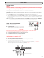
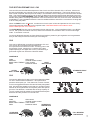
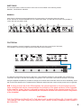
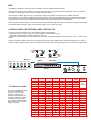
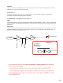
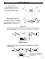
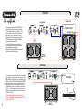
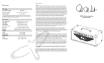
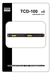
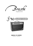
®
USER’S MANUAL
This manual contains a lot of information required to have in-depth knowledge
of the equipment. Therefore we recommend that you read this manual carefully
in order to use its potentials to the very best. All of our products are made on an
artisan basis and therefore you may find some small acoustic and/or structural
differences. This is the very best guarantee of a truly hand-made product.
®
TABLE OF CONTENTS
Pag
- INTRO
3
- SPECIFICATIONS
3
- TUBES LAYOUT
4
- FRONT PANEL
- Stand-by & Power
- Power, Protection and wording
- POWER AMP section
- CH1, CH2, CH3 section
5
5
6
6,7
- SWITCHING
- Manual
- Footswitch
- MIDI
- The twenty combinations
8
8
9
9
- REAR PANEL
- Effect loop
- Emulation / Slaving out
10
11
- GENERAL INFORMATION
- Serial/Parallel looping
- Preamp tubes
- Power tubes
12
13
13
- 059 USING EXAMPLES
- PRE OUT
- RETURN
- STANDARD
- FULL
- TRIAMP
- STUDIO
- STEREO
- SPEAKERS CONNECTION
14
14
15
16
17
18
19
20
2
WELCOME IN THE 059 WORLD !!!!
This new version, born from an evolution of the famous 059, represents the point of arrival for every
musician. The basic characteristics are still the same, and others have been added on making it even more
versatile and unique. The 20 combinations of sound, the various settings and all of the functions available
will allow you to find the sound that you are looking for, all tubes of course.
The head is equipped with a modern and unique system in its kind: the dual power amp to solve the problem
of volume once and for all. The first is a 20W in class “A” with two EL84s, while the second is a 100W in
class AB with four EL34s. The real news is represented by the fact that the choice of the amp to be used
can be selected from the front panel or the footswich or via midi in real time while you play without moving
on to stand-by or turning off the 059. With 20W you can create low volume solid sounds, even with small
sized cabinets, while with a 100W the pression is multiplied in a remarkable manner, creating a structure
and work classpower amp that are suitable for “live” use in large spaces. An added possibility that does
not exist in any other commercial amplifier.
059 has three entirely independent channels, which are all truly versatile. Extremes of the three channels
are superimposed perfectly, providing true continuity of sound between clean and true overdrive.
CH1 ranges from a clean and very balanced sound through to a very compressed and clean sound that
immediately reacts to the dynamics. A large harmonious and well defined structure. CH2 has an extremely
manageable gain, excellent for accompaniment rhythms, remaining consistent and defined, until reaching
the pushed overdrive. The feeling created by playing a CH2 is the cleanliness and definition of a CH1 but
with a progressive distortion…. a real “crunchy” tone!
CH3 ranges from this extreme point of the CH2 channel and creates a real, fluid and round distortion. The
PLEXI MODE and TONE REVERSE combinations will offer you several possibilities that will be extremely
important in all of your sound choices, guaranteeing “solo” in a completely unique way. The Tone Reverse
function that used to characterise the 059 is still the same, therefore being able to use equalisation of the
CH2 channel instead of the CH3 channel and vice versa, doubling the possibilities of sound. Another
modern function is the Plexi Mode that can be inserted in all three of the channels. In reality this apparently
simple function creates a complicated combination of operations by modifying the shape of each channel,
therefore allowing for a substantial variation of eq. Channels 2 and 3 will be smooth and full-bodied, while
CH1 will be much more compressed and larger. This function can also be stored.
SPECIFICATIONS
*
*
*
*
*
*
POWER AMPS
CHANNELS
TONE REVERSE
PLEXI MODE
AUX OUTPUTS
EFFECTS LOOP
*
*
*
*
TUBES
SWITCHING
DIMENSIONS
WEIGHT
20 W class A ( 2 x EL84) or 100W class AB (4 x EL34) Separated Volume / Presence (100W)
3 Completely separated (CH1 - CH2 - CH3)
Reverse the EQ of CH2 with the EQ of CH3
Works on the three channels preamp, changing their basic structure
EMULATED XLR balanced, LINE jack Slave, with level regulation
Tube buffered, usefull for rack and stomps. MIX control for Parallel/Serial use
True bypass function
6 x 12AX7 / 2 x EL84JJ / 4 x EL34SV-JJ
Manual / Footsw (INCLUDED) / Midi
720x250x230mm
19 kg
EQUIPMENT
- Power supply cord
- Footswitch with cable
- Operation manual
- Cover
ELECTRICAL CONNECTIONS
The electrical safety and correct operation of the device is only guaranteed with a good earth system.
Make sure that the power supply is the same as the one indicated on the back of the device.
3
®
TUBES LAYOUT
EL34
EL34
EL84
CH1
CH2
CH3
CH2
CH3
CH2
CH3
CH1
LOOP
DRIVER
V1
V2
V3
V4
V5
V6
12AX7
12AX7
12AX7
12AX7
12AX7
12AX7
EL34
EL34
EL84
CAUTION!!
The EL84 tubes can be replaced without any additional regulations as the 20W class A amplifier is in autobias.
However all of the new tubes must have the same “grade” (matched).
We strongly advise against the use of EL84 not selected in a couple.
The EL34 tubes on the amplifier in class AB with 100W can be replaced without any additional regulations
only if EL34 is used with the same matching, otherwise the bias must be regulated.
4
FRONT PANEL
STAND-BY & POWER
Caution !!
The head is fitted with an internal load which is automatically inserted when jacks speaker/cabinet are
NOT connected. This device will allow you to play even if the speakers are not connected, taking
advantage of the auxiliary outlets (see page 12).
The front panel of the head includes two switches to turn on and turn off the device.
ON ---> After having made all connections to the power supply, you can turn on the head using the following
procedure:
1) Lift the POWER (A) switch. The red lamp (B) on the front panel and on the device will turn on.
2) After at least 60 seconds you can lift the STD-BY (C) switch. This part of the network is protected by
two fuses, indicated by ''HT Fuse EL34'' and ''HT Fuse EL84'', located on the back of the device close to
the network plug.
OFF---> To turn the amp off, first of all press down the switch STD-BY (C) and then the switch POWER (B).
It is not necessary to wait for any specific period of time between the two operations.
POWER, PROTECTION AND WORDING
The back of the head includes:
D – An electrical socket.
E – A general protection fuse (T2A). The small drawer
contains a spare fuse, if the first one was to break.
CAUTION!!
If this fuse burns it means that the device has some kind of problem, normally rather serious.
We recommend you contact the dealer or your assistance center
F -- A high tension general protection fuse (HT) of the tubes EL34.
G – A high tension protection fuse (HT) of the tubes EL84.
CAUTION!!
If the F fuse burns all the amps (EL34 and EL84) cannot work. In this case we recommend you
contact the dealer or your assistance center.
H – This sticker contains the following information:
Line Voltage, value of the power fuse, serial number and production date.
I -- This sticker contains the following information:
Value of the protection fuse on the high voltage and the tubes EL34 (T630mA) SLOW BLOW
Value of the protection fuse of the tubes EL84 (F200mA) FAST
I
H
D
E
F
G
5
POWER AMP
The final section POWER AMP contains three controls:
* VOLUME of the 20W amplifier in class A
* VOLUME of the 100W amplifier in class AB
* PRESENCE allowing for the sound of the amplifier to exceed 100W.
N.B. This control does not work on the 20W amplifier!!
The independent volume controls for every finale offer the possibility of being able to have two levels of
power and sound entirely different and separated. This applies to solos, phrasing or parts that need to be
highlighted compared with normal accompaniments.
A practical example of this possibility lies in the use of the 20W amplifier for normal accompaniments,
while in order to create a solo with a clean sound but only with a higher level of volume, simply select the
clean channel with 100W by regulating the volume on the amp.
This allows you to create a volume boost by maintaining a perfectly clean and dynamic sound.
THE PREAMP SECTION
The three completely separate channels offer the maximum flexibility in terms of regulation and use.
It is also possible to add different colours, some of which can be set from the front panel while
others can be recalled and preset from the footsw. All of this can provide you with 20 possibilities
all of which can be pre-set and recalled using the Midi.
.
CH1
CH1 is a clean, well balanced and natural.
Using the PRE control you can “compress”
sound even more, without saturating it
The eq controls are standard (Treble, Middle e Bass)
but very efficent. It can be made even more brilliant
using the BRIGHT function.
CONTROLS
PRE
MASTER
BASS / MID / TREBLE
BRIGHT
Gain control
Channel volume control
Tone controls
Brightness control
If, however, you want to create a much more British sound, you can do so using the PLEXI MODE function that
can generate a real transformation to the characteristics of the pre-amplifier.
Of the two volume controls (PRE and MASTER), only the PRE acts on the Send level, so that when the level of
the MASTER is changed, the amount of the signal that reaches the effect is not changed in any way
6
THE SECTION PREAMP CH2 / CH3
CH2 and CH3 are the natural development of the Crunch and Solo channels of the “old” 059. Much more
dynamic and flexible, they normally range according to personal requirements. The level of silence (more
than halved compared with the previous model) in commutations and in background sound has been looked
after. The general quality of the circuit (in terms of design and components) has been drastically improved.
The function note TONE REVERSE of the first 059 version has been maintained and has made this amp real
flexible. Being able to exchange equalisation of the CH2 with that of the CH3, and vice versa, increases the
possibilities of sound available without the need for additional effects and with the convenience of being able
to do so using the pedal.
When the RAW function is inserted , it makes sound much more incisive and present but it is never “fuzzy”.
The medium and top range take on an important note. CAUTION! RAW function starts to work
with the GAIN pot from “6” to maximum
The PLEXI MODE function can be activated on these channels too. CH2 is transformed into a very British
Crunch, with prominent medium-low tons, while CH3 increases and smoothes down on the medium-high
notes. A revolution in sound!!
On the two distorted channels we have drawn three imaginary areas for gain regulation and we guarantee
that you will easily find the sound that you are looking for.
CH2
CH2 can be defined the connecting ring between CH1 and
CH3. Its rich and consistent sound is perfect for
accompaniments as well as for solos. Its strong point is the
progression of gain, ranging from a reactive dirty-clean
(superimposing on the upper limit of CH1) until reaching a
good level of gain from which the CH3 then leaves.
CONTROLS
GAIN
MASTER
BASS / MID / TREBLE
RAW
Gain control
Channel volume control
LIGHT
Tone controls
DISTORTION
Presence control
CLEAN
DIRTY CLEAN
STANDARD ROCK
DRIVE
CH3
CH3 can be defined as Hi-gain but it is also extremely suitable
for use in several kinds of situations. Its impact and its
presence will surprise you. This channel is, in terms of sound,
much more aggressive than the CH2 and obviously has greater
gain. Its harmonious wealth is such that you can also use this
channel for accompaniments and rhythmic parts with specific
grooves. The definition, combined with the huge capacity of
"punch" makes the CH3 suitable for all situations that require
thickness and the presence of a sound front.
CONTROLS
GAIN
MASTER
BASS / MID / TREBLE
RAW
STANDARD
DISTORTION
Gain control
Channel volume control
Tone controls
Presence control
HARD/ROCK
DISTORTION
FULL MODERN
DISTORTION
7
SWITCHING
The channels and the various functions of the 059 can be handled in the following modes:
MANUAL, FOOTPEDAL and MIDI
MANUAL
Apart from the lighted functions highlighted in the image below, the manual system also allows
for the selection of switches: BRIGHT on CH1, and the two RAW on CH2 and CH3, that are not possible to
control with the foot pedal or Midi.
G G
G
G
G
G
G
G
G
FOOTPEDAL
With its supplied 7-function footpedal, connected with the 7pin plug on the back of the head,
it is possible to control every single function illuminated on the front panel.
0
10
The SW plug of the head is the same to which the 7-pin footpedal (supplied) or the possible midi controller are
connected. The logic of the 059 automatically recognises if one or the other control device has been connected.
Using the supplied footpedal it is possible to change the channels and activate the various functions individually, while
with a midi footsw presets can be created with the definitions desired and then various sound presets can be organised.
N.B. If during normal use of the 059 footpedal, the manual switches on the front panel are also
used, misalignement may be created between the indication of the panel and those of the footpedal.
In this case the system can be re-aligned by pushing the footsw of the selected channel (CH1 or
CH2 or CH3) on the footpedal. Automatically the front panel will show the same functions configuration
of the footpedal.
CAUTION!!
THE FOOTPEDAL SUPPLIED WITH THE 059 IS NOT A MIDI CONTROLLER. IT CAN BE USED
TO CHANGE THE FUNCTIONS ILLUSTRATED BUT PRESETS AND COMBINATIONS CANNOT
BE CREATED.
8
MIDI
The 059 can handle the various functions via MIDI, using a standard MIDI controller.
The Midi Thru plug is not provided for, so the 059 must always be connected to the last position, receiving the Midi
command, for example, from the Thru/Out plug of another device.
059 receives in OMNI, that is to say it recognises programme changes arriving from all 16 MIDI channels.
Upon request it is possible to modify programming of the processor if the need arises to limit and therefore to receive
and recognise just one of the 16 Midi channels of the head. This requirement generally arises when the same Midi
controller has to control several Midi devices and has to achieve different kinds of combinations.
The FOOTSW / MIDI IN plug is a 7-pole Din that transmits the MIDI signal and also the phantom 12Vdc power to feed
the external MIDI controller. If this is not required, simply use a 5 pole Din cable.
STORING USING THE EXTERNAL MIDI CONTROLLER
In order to save the settings to be used via Midi, follow this procedure:
- Select the preset on which you want to save using the midi footswitch (eg.1)
- Select the preset desired from the multi-effect. (eg. 23)
- Select the channel desired from the head (eg. CH2) and any possible additional functions (eg. Loop + 100W + Plexi
mode)
Once the desired condition has been set, press the luminous button related to the channel selected (CH1 or CH2 or
CH3) for a few seconds until the red LED "STORE LED" starts to flash, being the same led of the Tone Reverse function.
G
G
MIDI OUT
A/B
1
2
3
4
MIDI IN
MIDI THRU
5
23
Effect
Midi Footswitch
0
Setting
no.
1
2
3
20 different sounds
4
5
Via midi it is possible to handle
in an easy and flexible
manner, control of the 7
functions and up to 20
different combinations can
be saved. This wide choice
combined with the preset
of a possible external effect
will provide you with a wide
range of sounds.
6
7
8
9
10
11
12
13
14
15
16
17
18
19
20
CH1
CH2
CH3
X
X
X
X
20W
10
100W
X
X
X
X
X
X
X
X
X
X
X
X
X
X
X
X
X
TONE
REVERSE
Active on
CH2 e CH3
X
X
X
X
X
X
X
X
X
X
X
X
X
X
X
PLEXI
MODE
X
X
X
X
X
X
X
X
X
X
X
X
X
X
X
X
X
X
X
X
X
X
9
REAR
PANEL
LOOP EFFECTS
This section, due to the effects on the rear panel, contains SEND, RETURN, MIX% and PRE OUT. The SEND
is the output used to transmit the signal to the Input of the effect. It has been studied for pedal effects (stomp
efx) and rack unit effects (rack efx). RETURN is the input that reaches the final amplifier. The processed signal
from the output of the effect normally enters at this point and is destined to be mixed with the original sound of
the amplifier through the MIX% control. It is also possible to enter into the Return with an external Preamp, taking
advantage of the final part of the amplifier of the head (see example "RETURN").
In any case, we recommend the use of high quality and short protective cables for all of these connections of
the loop section. Furthermore, we must point out that, in general, any kind of effect used will tend to modify the
original sound of the amplifier according to the quality.
The MIX% control can be regulated in order to achieve:
- No effect ---> position 0%
- Parallel loop ---> intermediate positions (for example) at 60 %.
This indicates 60% of the (Wet) effect and 40% of direct sound (Dry).
- Serial loop ---> position 100%
The SEND level and the PREOUT level depend on the level
(position) of the PRE and GAIN controls of the three channels.
PEDAL EFFECT
PEDALE
For maximum sound performance, we recommended that only modulation effects are inserted into the loop such
as chorus, flanger, delay, reverb etc. Set the MIX% control to the 100% position (serial loop), the entire signal will
move through the effects. Generally the modulation pedal include a Level control that you should set,
according to how much effect you desire. With the use of the pedal we recommend that you do not use volumes
that are too high in order to avoid saturation of the pedal with the signal from the Send.
OUT
IN
RACK EFFECT
Using the rack effect we recommend that the direct (Dry) is excluded from the effect and mixing between the sound
of the head and that of the effect (Wet) should be handled with the MIX% control according to your personal taste
(Loop in parallel). The IN volume of the effect must be regulated with the real volume of the head used, checking to
make sure that in this condition the signal transmitted by SEND does not saturate the effect, while the OUT volume
of the effect must be consequently regulated in order to achieve a good balance between the volume and the amount
of the effect.
EFX
DRY
Volume IN
Volume OUT
0%
WET
100%
OUT
IN
10
PRE OUT
Is the out of the pre-amplified signal. This out may be used to send an external amplifier with its relative
cabinet or for a Triamp system (see example).
SPEAKER OUT
These two outs (paralleled) must be connected to one or more cabinets, matching the impedance.
From these out cames the power signal of the head.
The SLAVE OUT section contains the following outs:
LINE
A signal extracted from the power amplifier to be send to another amplifier or effect. This out is unbalanced
and not emulated. Compared with the PREOUT this outlet confers sound to the sound characteristic of the
power amp.
EMULATED
A signal extracted at the same point of the LINE but apart from being softened, it is also filtered, therefore
modelled according to the reaction of the speaker. This is done to create a direct line with the mixer. A
balanced and floating transformer XLR.
GUITAR
SPEAKER OUT
IN
PRE
MIX
POWER
RETURN
SEND
PRE OUT
SLAVE OUT
LEVEL
CONTROL
LINE
FILTER
EMULATED
059 is fitted with a circuit called ALS (Automatic Loading System), that offers the
following two advantages :
- playing without a speaker cabinet using the outlets LINE and EMULATED,
- protecting the final stages from breakages created by use without any power load.
Internal loading is connected automatically, if some of the jacks are NOT connected
with SPEAKER OUT.
11
GENERAL INFORMATIONS
SYNTHESIS EFFECTS
The main characteristic of the synthesis
effects (see example) is to physically
modify the shape of the signal (see
DISTORTION example). This family of
effects is perfectly inserted into the chain
of connections between the guitar and the
amplifier input.
IN
EFX
OUT
Input
Output
MODULATION EFFECTS
The main characteristic of the modulation effects
(see example) is to add and/or superimpose other
curves/shapes with the inward signal. This family
of effects is perfectly inserted into the chain of loop
effect connections of your amplifier, that is to say
between the pre-amplifier (Preamp) and the
amplifier (Power amp)
IN
EFX
OUT
Input
Output
SERIAL LOOP
In the serial loop all of the outward signals from the Preamp are transmitted and processed by the
effect. In this case setting of the effect should consider part of the original sound defined as DIRECT
or DRY and part of the EFFECT or WET effect created from the original sound and mixed with the
direct or dry within the effect.
IN
LOOP
PRE
POWER
SEND
OUT
RETURN
IN
OUT
DIRECT
MIX
EFFECT
EFFECT
PARALLEL LOOP
In the parallel loop a portion of the direct sound passes through the loop without leaving the Send
and then mixes with the signal from the Return. The quality of the effect is much less important
compared with the serial loop, as the direct will be maintained as the original from the internal
passage to the loop.
DIRECT
IN
PRE
MIX
LOOP
SEND
IN
POWER
OUT
RETURN
DIRECT=0%
DIRECT
OUT
MIX
EFFECT
EFFECT=100%
EFFECT
In order to have the best sound
you must kill the Direct signal
of the effect.
12
GENERAL INFORMATIONS
PRE-AMPLIFIER TUBES
The pre-amplifier tubes are not normally subject to wear and tear and may last more or less for "the entire lifespan of
the device".
Possible problems on this kind of tube are related to microphonic effect and noise.
Microphonic noise effect
Defined as a secondary effect of the tube of producing external vibrations as well as electrical signals, generating horrible
frequencies (whistles). This phenomenon is even more evident on high earning levels such as distorted channels.
With the amplifier on and the load correctly connected, if knocks are made to the glass of the pre-amplifier tubes, it is
normal to hear reproduction of this sound through the speaker.
Microphonic noises are clear and different because it will be possible to hear (whistles and interference) and in some
cases also distortion of sound even without hitting the tubes.
It is important to point out that the first tube of the chain is the one that more than any other will tend to reproduce
percussion generated by ourselves. Therefore it is the one that is subject the most to the microphonic part of the chain.
Noise
An intrinsic characteristic of the tubes is the background noise that borns from the natural operation.
During the lifespan of a tube, this noise may increase dramatically by creating problem of various kinds.
The pre-amplifier tubes do not necessarily need to be selected electrically (this is normally performed by the manufacturer),
but it is important to make sure that they are of excellent quality.
POWER TUBES
The power tubes are the last stage of amplification (before the output transformer and the speakers) and are subject to
wear and tear.
On average a final tube that works in class A/B may last between 800 and 1,000 working hours, considering that their level
of wear and tear is also connected with the volumes of sound.
On an amplifier of the same power working in class A, the same tube may last between 600 and 800 hours. In this working
class the tube is subject to greater stress.
When the final tubes should be replaced
It is possible to see when a tube is exhausted because it has a general loss in power and therefore in volume, sound has
less impact and low frequencies tend to lose power.
The main problems related to this kind of tube are:
- a short circuit within the tube that normally blows the high tension fuse (HT)
- one of the tubes does not light, a fault that can be easily identified by a visual control on the internal filament of the
tube itself
- the tube becomes incandescent, in this case an increase in the background noise of the amplifier (hum) will be registered,
a visual control of the tubes will confirm this kind of defect.
In all of the fields mentioned above, it is important to replace the faulty tube with a new one.
If the faulty tube is not new, therefore if it has worked for approximately 1 year, we recommend that all of the tubes are
replaced.
This is done to optimise performance. If, however, the tube is relatively new, then simply replace it with an identical one.
Caution!
Make sure that only coupled tubes are assembled, with the same selection characteristics that can generally be
identified on the tube with the indications given by the manufacturer (in our case MATCHING REFERENCE).
All of the final tubes fitted onto an amplifier must have this common characteristic. If sets of tubes are used
with a different matching reference the BIAS must be realigned on the amplifier.
13
®
PRE OUT
B system
A system
In normal use of the head, the PREOUT
outlet may be used to connect another
Power Amp with relative speaker. The
two systems A and B may be used at
the same time. The PREOUT level
depends on the level (position) of the
PRE controls on CH1 and the GAIN
controls on CH2 and CH3.
In order to find a balance between
system A and B, the controls should
be subsequently adjusted.
Master and Volume on 059 and volume
on the external Power Amp.
In POWER AMP
Speaker Out
16
4
8
10
0
4x12''
MONO
8Ω
2x12''
MONO
RETURN
Out
16
0
10
PRE AMP
In
8Ω
Chitarra
4
8
If an external pre-amp is to be used, it is possible
to do so by connecting it to the return of the
059. With this connection, by positioning the
MIX% control 100% and inserting the LOOP
control on the front panel or on the footsw,
the pre-amplifier of the head is excluded.
The Master control of the channel selected
(CH1, 2 or 3) remains active, therefore it is
another volume before the power amp one
of 20W or 100W.
In this configuration we recommend use
of one of the three channels and use of the
relative MASTER
14
2x12''
MONO
®
STANDARD
8
16
4
0
10
Midi 5 pin
cable
DRY
Volume IN
Midi Thru
Volume Out
Midi In
Midi 7 pin
cable
MIDI OUT
A/B
4x12''
MONO 16Ω
1
2
3
4
Midi Footswitch
5
0%
WET
100%
IN
OUT L
OUT R
EFX
15
®
FULL
16
4
8
0
10
4x12''
MONO 16Ω
Midi 7 pin
cable
In
In
POWER AMP
16Ω Speaker Out
4x12''
MONO 16Ω
4x12''
MONO 16Ω
4x12''
MONO 16Ω
POWER AMP
16Ω Speaker Out
16
®
TRIAMP
Midi 7 pin
cable
8
16
4
0
The Tri-amplification system is made up of
three different sound sources. The original
sound of the amplifier (DRY) is in the middle,
while the two channels (L&R) are located on
the sides, with the sound effect only (WET).
This configuration increases the space of the
sound front in particular using modulation
effects such as reverbers, delay, chorus in direct
listening or from the PA (with microphones on
all three speakers).
In this configuration the mix between the original
sound and the effect is regulated by the general
VOLUME of the head and by the volumes of
the two channels of the power stereo amplifier.
10
DRY
Volume IN
0%
Volume Out
WET
100%
IN
OUT L
OUT R
EFX
In L
In R
8Ω
8Ω
Out L
STEREO
POWER AMP
Out R
16Ω
8Ω
8Ω
17
2x12''
MONO
4x12''
MONO 16Ω
2x12''
MONO
LEFT CHANNEL
DRY SOUND
RIGHT CHANNEL
®
OUT
PEDALE 1
IN
PEDALE 2
OUT
PEDALE 3
STUDIO
IN
OUT
IN
16
4
8
0
10
8Ω
IN
OUT
IN
OUT
PEDALE 6
OUT
PEDALE 5
RECORDING
PEDALE 4
XLR
CABLE
IN
Midi cable
L R
OUT
Send
EFX
EFX
EFX
L
Return
R
Phones
Midi Thru
2x12''
MONO
DRY
Volume IN
Midi In
0%
Volume Out
Mixer
WET
100%
OUT R
4
5
OUT L
IN
EFX
MIDI OUT
Midi cable
A/B
1
2
3
Midi Footswitch
18
Headset
®
STEREO
HEAD A
HEAD B
16
8
8
16
4
4
0
10
0
DRY
Volume IN
16Ω
Midi Thru
Midi In
WET
40%
Volume Out
10
60%
IN
OUT L
OUT R
EFX
16Ω
MIDI OUT
Cavo midi
7 poli
A/B
1
2
3
4
5
Midi Footswitch
19
LEFT CHANNEL
RIGHT CHANNEL
4x12''
MONO
4x12''
MONO
®
SPEAKER CONNECTIONS
SET TO
Speaker
16
16Ω
1x12''
MONO
SET TO
Speaker
8
Speaker
1x12''
MONO
16Ω
8Ω
1x12''
MONO
SET TO
16
4
8Ω
16Ω
1x12''
MONO
Speaker
8Ω
8
16Ω
SET TO
Speaker
SET TO
1x12''
MONO
SET TO
Speaker
16Ω
8
16Ω
2x12''
MONO
20
4x12''
MONO
4x12''
MONO
4x12''
MONO
IMPORTANT NOTES
- The manufacturer declines all responsibilities in terms of damages to people,
things and/or animals caused by incorrect use of the appliance.
- Compliance of the appliance is highlighted by the CE symbol shown on the back.
- The manufacturer reserves the right to make any modifications to its product that it may consider
necessary and useful, without compromising the functional characteristics and safety of the
product.
- Do not use the appliance when bare footed.
- Do not use the appliance with wet hands and/or feet.
- Do not leave the appliance exposed to atmospheric agents (rain, sun, humidity etc.)
- Do not allow children or any unskilled individuals to use the appliance.
- Avoid putting inflammable material close to the appliance.
- Fill in the warranty form that you will find on the website WWW.BRUNETTI.IT, otherwise the
warranty will not be valid.
- Repairs to the appliance may only be carried out in our premises during the warranty period
and, in any case, only by authorised technicians in accordance with applicable national norms
and directives.
- Periodically check the cables supplied together with the appliance. If they appear to be scratched,
cut or burnt etc. replace them immediately with similar cables.
-In the event of a fault contact the shop that you bought the appliance from.
- Make sure that the appliance is correctly earthed in accordance with applicable national norms
and regulations.
Info & Support :
Brunetti Marco & C. S.a.s
Via De' Bonomini, 25/27
41100 MODENA ITALIA
Phone number : +39 059 243404
Fax number : +39 059 216464
e-mail : [email protected]
commercial info
e-mail : [email protected] technical info
http//:www.brunetti.it
®
CH1 SETTING
1-1
1-2
1-3
1-4
1-5
1-6
1-7
1-8
CH2 SETTING
2-1
2-2
2-3
2-4
2-5
2-6
2-7
2-8
CH3 SETTING
3-1
3-2
3-3
3-4
3-5
3-6
3-7
3-8