1
Product Solutions Group
Fujitsu TeamPoS OPOS User’s Guide
Version 1.13.0
Feb 29, 2012
Status: Rel
Channels: ALL
Author: DJ
Fujitsu OPOS 1.13
(Release 1.13.0)
Configuration and Setup
FOR
Fujitsu TeamPoS
&
POS Peripherals
02/29/2012
Fujitsu Frontech North America Inc.
Document Number:
Revision Number: 1.13.0
Document Name: FjOPOS_1_13_0.PDF
Fujitsu OPOS 1.13 Configuration and Setup
Table of Contents
1.0
FUJITSU - OPOS OVERVIEW ........................................................................................................................4
1.1
FUJITSU - OPOS RELEASE OVERVIEW AND HISTORY .......................................................................................4
1.2
FTXS - OPOS 1.10.1 AND LATER SUPPORTED DEVICES............................................................................... 11
1.3
DEFAULT SCANNER AND SCALE PROGRAMMING ............................................................................................ 13
2.0
OPOS ARCHITECTURE .............................................................................................................................. 14
3.0
HARDWARE/SOFTWARE INTERFACE ..................................................................................................... 15
3.1
DRIVER REGISTRATION ................................................................................................................................ 15
3.1.1 USB VIRTUAL COM (VCOM) PORT INSTALLATION ....................................................................................... 15
3.2
TEAMPOS 3600 .......................................................................................................................................... 15
3.3
TEAMPOS 3000 .......................................................................................................................................... 16
3.3.1 LEGACY PORTS BOARD (TEAMPOS 3000) PORT ASSIGNMENTS .................................................................... 16
3.3.2 USB OPTION BOARD (TEAMPOS 3000) PORT ASSIGNMENTS........................................................................ 16
3.4
TEAMPOS 2000 .......................................................................................................................................... 17
3.4.1 TEAMCOM (TEAMPOS 2000) COM PORT IRQ AND IO ADDRESSES ............................................................. 17
3.4.2 TEAMCOMBO (TEAMPOS 2000) COM PORT IRQ AND IO ADDRESSES ........................................................ 17
3.4.3 TEAMUSB (TEAMPOS 2000) VIRTUAL COM PORT ASSIGNMENTS ................................................................ 19
3.5
COM PORT REGISTRY SETUP (TEAMPOS 2000) FOR W IN2000/W INDOWS XP .............................................. 20
3.5.1
TeamCOM COM Port Settings (7 RS 232 Ports) .............................................................................. 20
3.5.2
TeamCOMBO (TeamPoS 2000) COM Port Settings (4 RS 232 Ports) ............................................ 22
3.6
POS KEY SCAN CODES FOR 133PQ, 104 KEY, AND 32 KEY KEYBOARDS ...................................................... 23
3.6.1
133PQ Keyboard Layout.................................................................................................................... 23
3.6.2
104 Keyboard Layout ......................................................................................................................... 24
3.6.3
32-Key Keypad Layout ....................................................................................................................... 25
3.7
OPOS MSR TRACK CONFIGURATIONS FOR 133PQ, 104 AND 32-KEY KEYBOARDS ....................................... 27
3.8
OPOS TEST UTILITIES ................................................................................................................................ 27
3.9
MICROSOFT RUNTIME SUPPORT FILES ......................................................................................................... 28
4.0
TEAMPOS HARDWARE SETUP................................................................................................................. 29
4.1
TEAMPOS 3600 AND TEAMPOS 3000 .......................................................................................................... 29
4.1.1 LEGACY INTERFACE OPTION ........................................................................................................................ 29
4.1.2 USB INTERFACE OPTION ............................................................................................................................. 31
4.2
TEAMPOS 2000 .......................................................................................................................................... 33
4.2.1 OPOS 1.10 INSTALLATION NOTES ............................................................................................................... 33
4.2.2 TEAMCOM (7 RS232 PORTS) BOARD SETUP FOR TEAMPOS 2000 .............................................................. 35
4.2.3 TEAMCOMBO (4 RS232 / 4 USB PORTS) BOARD SETUP FOR TEAMPOS 2000 ............................................ 37
4.2.4 TEAMUSB (7 USB PORTS) BOARD SETUP FOR TEAMPOS 2000 ................................................................... 39
4.2.4.1
TeamUSB default port details: ....................................................................................................... 41
4.2.5 TEAMCOM BOARD SETUP FOR TEAMPOS 5000 ........................................................................................... 41
4.5.1
TeamCOM POS Printer Jumper Setup .............................................................................................. 41
4.2.5.2
SMC Ethernet Card ........................................................................................................................ 41
4.2.5.3
3COM EtherLink III Card ................................................................................................................ 41
4.2.5.4
Sound Card .................................................................................................................................... 41
5.0
TROUBLESHOOTING ................................................................................................................................. 42
5.1
COMMON PROBLEMS ................................................................................................................................... 42
5.2
3COM –TEAMCOM ADDRESS CONFLICT ..................................................................................................... 43
6.0
TEST INSTRUCTIONS ................................................................................................................................. 45
6.1
INSTRUCTIONS FOR TESTING THE FTXS OPOS SERVICES FOR TEAMPOS DEVICES ....................................... 45
6.2
INSTRUCTIONS FOR TESTING THE FTXS OPOS SERVICES FOR THE 92R/M/U KEYBOARD DEVICES ................. 47
6.3
INSTRUCTIONS FOR INSTALLING AND VERIFYING THE EPSON TM-H6000 OR TM-T88 OPOS INSTALLATION ..... 48
6.4
INSTRUCTIONS FOR INSTALLING AND VERIFYING THE PREH 133UQ KEYBOARD OPOS INSTALLATION .............. 48
6.5
INSTRUCTIONS FOR INSTALLING THE COMMON CONTROLS ............................................................................. 48
7.0
SCANNER AND SCALE HARDWARE INITIALIZATION BARCODES...................................................... 49
7.1
SCANNER HARDWARE INITIALIZATION BARCODES FOR USE WITH THE FTXS OPOS DRIVERS .......................... 49
Fujitsu Frontech North America Inc.
2
Fujitsu OPOS 1.13 Configuration and Setup
7.2
9900 SCANNER/SCALE HARDWARE INITIALIZATION BARCODES FOR USE WITH THE FTXS OPOS DRIVERS....... 50
APPENDIX A. NOTES ON WINDOWS 7................................................................................................................ 52
A-1 VIRTUALIZED REGISTRY HIVES & ASSOCIATED VIRTUAL STORE HIVE ............................................................. 52
A-2 VIRTUALIZED FOLDERS & VIRTUAL FOLDER .................................................................................................. 52
A-3 FILE AND REGISTRY VIRTUALIZATION ENABLE/DISABLE; USER ACCOUNT CONTROL (UAC) ENABLE/DISABLE VIA
CONTROL PANEL ......................................................................................................................................... 52
A-4 FILE AND REGISTRY VIRTUALIZATION ENABLE/DISABLE; USER ACCOUNT CONTROL (UAC) ENABLE/DISABLE VIA
REGISTRY ................................................................................................................................................... 52
A-5 SAMPLE REGINI.EXE USAGE ......................................................................................................................... 53
A-6 SAMPLE REG.EXE USAGE ............................................................................................................................. 53
APPENDIX B. VF6X CHARACTER TABLE SELECTION ..................................................................................... 54
Fujitsu Frontech North America Inc.
3
Fujitsu OPOS 1.13 Configuration and Setup
1.0
Fujitsu - OPOS Overview
1.1
Fujitsu - OPOS Release Overview and History
The purpose of this document is to provide information needed to install and operate the POS peripheral device
framework for client applications based on OPOS 1.10 (OLE for Retail POS). The OPOS specification fully
describes the Fujitsu device interfaces and provides complete specifications for client applications to be
developed immediately. Client applications call the OPOS device “Control Object” (CO) which in turn calls the
OPOS device “Service Object” (SO).
Release 1.13.0
Release 1.13.0 provides support for the TeamPoS 7000 POS Terminal and the new peripherals that are being
introduced with the TeamPoS 7000 release. It also is an update and maintenance release that includes
corrections and updates to currently supported devices.
New Devices Supported:
TeamPoS 7000 Cash Drawer Service to support the on-board cash drawer port. The on-board cash
drawer port is accessed via a HID USB interface. The port is controlled by firmware that manages the
command and status messages needed to control the drawer.
CT11 Single Station USB/HID interface Printer.
VF35 Service for the Small 2 X 20 VFD display.
VF70 Service for the Standard 2 X 20 VFD display.
TeamMSR (and TeamKeypadMSR for the new USB/HID interface MSR that can be attached to the
TeamPoS 7000 Axxx LCD Display.
Hardware:
TeamPoS 7000 A100/A200/A300:
Basic I/O ports:
On-Board USB for Cash Drawer/Power/Proximity HID
2 x Standard 5V USB A Connector Ports
3 x 12V Powered USB Connector Ports
On-Board 5V Standard USB Proprietary Connector for TeamMSR HID
On-Board 12V Powered USB Proprietary Connector for VF35 VFD HID
On-Board 24V Powered USB for POS Printer
Extended I/O Ports:
2 X Rs232 Serial 5V Ports
2 Standard 5V USB Ports
I/O Box Ports:
Fujitsu Frontech North America Inc.
4
Fujitsu OPOS 1.13 Configuration and Setup
5 x RS232 Serial 5V
1 x PS2 Keyboard / Mouse Combo Port
Maintenance Items in Release 1.13.0:
FJOPOS Install: Corrected extraneous VF60-2 Registry Data when VF60-2 not installed.
FjScanSO.dll for SS1200 Scanner: Fixed Decode Data to set ScanDataType property correctly for ITF 2
of 5 and Code 39.
FjScanSO.dll: Fix in Direct I/O m_Command not being cleared after use.
Release 1.10.8
Release 1.10.8 is primarily an update and maintenance release that includes corrections and updates for the
following:
36xx Cash Drawer Service updated to support non-Fujitsu cash Drawers. Registry parameter
‘Status_Mode’ set to ‘Invert’ for non-Fujitsu drawers, and set to ‘Normal’ for Fujitsu drawers.
VF60, CT10 and D22/25 MSR registry entries updated to include the driver restart parameters:
‘RestartType’ and ‘RestartHardwareID’. This allows the services to restart the USB driver if device is
disconnected due to ESD.
Release 1.10.7
Release 1.10.7 is primarily an update and maintenance release that includes corrections and updates for the
following:
TeamPoS 36xx Cash Drawer service added to support the Cash Drawer I/O Option Card for the
TeamPoS 3600 POS Terminal.
VF60 Line Display – support added for code page 1252 (selects character table 6).
CCOVDF.EXE updated for code page 1252 testing.
FjOPOS_1_10_7 install package updated to include 1252 in CharacterSetList registry entry.
“TeamPoS 3000 VF60 Character Table Selection” PDF document added to the install
CT10 Printer service object required additional fixes to handle CR/LF and LF/CR correctly.
FjOPOSTest – Key lock test now checks for error codes and reports.
D22/25 Key Lock service allows time for keyboard to respond to key position and reports a no-response.
CT10 Printer – Code 128 corrections and default 128 code type added.
Release 1.10.6a
Release 1.10.6a is an update release that sets Threading Model to Apartment for the following device services:
TP15 Cash Drawer, TeamPoS 3000 Power, CT10 Printer, CT10 Cash Drawer, D22/25 MSR and Key Lock, and
the VF60 Line Display.
Release 1.10.6
Fujitsu Frontech North America Inc.
5
Fujitsu OPOS 1.13 Configuration and Setup
Release 1.10.6 is primarily a maintenance release that incorporates the transition from Fujitsu Transaction
Solutions Inc. (FTXS) to Fujitsu Frontech North America Inc. (FFNA) and also includes corrections and updates
for the following:
The install package has been renamed to FjOPOS_1_10_6.exe.
The default install folder is changed from \Program Files\OPOS\FTXS to \Program Files\OPOS\Fujitsu.
A message is added to the install stating that older versions of FTXS OPOS should be removed before
installing Fujitsu OPOS 1.10.6. This message is only generated if the older version’s Service Information
Key is found in the registry.
FTXSOPOSTest.exe and FTXSOPOSSetup.exe have been renamed to FjOPOSTest.exe and
FjOPOSSetup.exe respectively.
FJ.bmp (bit map logo for printer test) has been included in the CCO test programs install files.
CT10 dual drawer install no longer sets the ‘Status_Mode’ registry parameter for both drawers to ‘Invert’.
It is now set to ‘Normal’. A Fujitsu cable for Fujitsu drawers (TP10 and TP15) is now available.
Release 1.10.5
Release 1.10.5 is primarily a maintenance release with corrections and updates for the following:
FTXS OPOS install now includes a selection to install the CCOxxx test programs and other utilities
without having to install the corresponding Fujitsu device.
FTXS OPOS install now includes selections for TeamPoS 3000 XL, XT, XL², XE, and TeamPoS 36xx
platforms.
FTXS OPOS install: Added SetSBCS=F (default), CharacterSet=101 (default) and SetInternational=0
(default) to the VF60 Line Display registry entry during installation. See Appendix B to utilize these
settings to select VF60 character tables for characters in the range 128 – 255, and to select some
international characters.
FTXS OPOS install: Added all Character Sets to the VF60 Line Display registry entry for the
CharacterSetList property.
VF60 service object: Corrected a problem in selecting the Line Display’s character page 19H.
CCOvfd test program: Includes a 250ms delay between the text display and the display mapped
characters command to properly display the character range selected.
CCOvfd test program: Displays the CharacterSetList on the prompt to set the CharacterSet property.
SymphSO (scanner/scale): Added support for the 9900 without long timeout delays for unsupported
features.
CT10 Printer service: Corrected to allow carriage return/linefeed in the text without causing extra
linefeeds in the output.
Release 1.10.4
2
Release 1.10.4 is a release for the TeamPoS3000XL and Windows 7™.
A problem in the VF60 line display service object was fixed that was encountered with the
2
TeamPoS3000XL motherboards.
A problem in the CT10 service object and port object was fixed that was encountered with the
2
TeamPoS3000XL motherboards.
Fujitsu Frontech North America Inc.
6
Fujitsu OPOS 1.13 Configuration and Setup
FTXSOPOSTest.exe was changed to allow the test program to run in normal mode on Windows 7 and
Windows 7 when User Account Control is on.
Release 1.10.3
Release 1.10.3 is primarily a maintenance release with corrections and updates for the following:
A problem was fixed in all the TeamPoS 3000 device services that could cause a problem if the
application made a request at the same time the device issued a notification.
Corrections were made to the TeamPoS 3000 device services event logging.
Corrections were made to the TeamPoS 3000 device services to resolve some missing exclusive queue
accesses.
Problems with close requests from multiple applications at the same time were corrected in the TP15
cash drawer and TeamPoS 3000 power services.
A temporary solution for the “taskkill /f” shutdown issue has been implemented in the TP15 cash drawer
and TeamPoS 3000 power services. The issue causes the application to take up to 5 minutes to
shutdown if it is forcefully terminated while either the cash drawer or power device is open.
Memory switch 3-8 of the CT10 printer needs to be set to “Closed” to prevent the printer from hanging in
an error mode if the cover is opened while printing. Refer to the Printer’s User’s Manual for the switch
setting procedure. Later firmware releases will have this setting as the default.
CT10 Printer service object has been corrected to accept the PTR_BCS_Code128_Parsed symbology
parameter to the PrintBarCode method.
Error Reporting has been added to the D25 MSR service.
The VF60 Line Display service object has a fix to the ReleaseDevice method for a hang that could occur if
power notify is enabled.
The NUMLOCK ON requirement has been removed from the 133PQ/104P/32K/A12 MSR.
The 92U MSR error reporting has been corrected.
Some of the CCO and FTXS test programs have corrections and enhancements.
Release 1.10.2
Release 1.10.2 was primarily a maintenance release with corrections and updates for the following:
100% CPU use by the Power Management Utility when main application terminates.
D22/25 MSR sentinels decoding problem.
RetrieveStatistics – XML format correction.
92R/M Error on Open/Claim.
CT10 Dual Drawer Install updates.
FTXSTEST corrections and enhancements.
Internal SO changes for consistent use of synchronization objects.
With release 1.10.1 came support for the Fujitsu TeamPoS 3000 POS terminal and additional POS devices. The
new devices, except for the cash drawer and power management, are supported on both the TeamPoS 2000 and
TeamPoS 3000 platforms.
Fujitsu Frontech North America Inc.
7
Fujitsu OPOS 1.13 Configuration and Setup
Starting with release 1.10.1, only support of the Common Control Objects (CCOs) is provided. These are
available from http://monroecs.com/. The CCOs should be downloaded and installed as a separate installation
step from the FTXS OPOS installation.
Service Objects for all devices except the FJ Power and the FD20/21 dot matrix printers have been updated to
either the OPOS 1.9 or OPOS 1.10 specification. The FD20/21 printers will remain at the OPOS 1.3 level; while
the FJ Power (TeamPoS 2000 and TeamPoS 3000) is a custom implementation prior to POSPower being added
to the OPOS specification. POSPower for OPOS 1.9 is available for the TeamPoS 3000 only.
Device Statistics Retrieval has been added to all of the 1.10 devices. Not all devices provide all of the statistical
information identified in the OPOS specification, but the information that is provided is retrieved and can be
obtained by the RetrieveStatistics() method. Some devices can provide additional information – this information is
retrieved and reported as “Manufacturer Specific”.
Features Added in 1.10.1 for specific Devices:
VF40/50 Line Display:
DefineGlyph method added.
Reverse and Reverse-Blink character attributes added.
Escape sequence processing added for Reverse, Blink, Reverse-Blink and Normal added.
Check Health Internal and External now request a response from the Line Display device.
133PQ and 92R/M/U MSR:
Transmit Sentinels ON/OFF support added.
ClearInputProperties method added.
Scanner (SlimScan 1200 and Symphony 9950)
RSS14 barcode support added (requires firmware upgrades)
RSS14 extended barcode support added (requires firmware upgrades)
ClearInputProperties method added.
All Legacy Devices (not available for TeamPoS 3000 devices)
Tracing (Logging) to a file (Warning: This can cause some performance issues so only use if necessary).
The enable and maximum file size are controlled via registry entries. Available only in debug versions of
the service objects.
Periodic Statistics updates to the Registry. The enable and rate are controlled via registry entries.
Fujitsu Frontech North America Inc.
8
Fujitsu OPOS 1.13 Configuration and Setup
New Devices Added in 1.10.1 Release:
Cash Drawer for the TeamPoS 3000
Power Management for TeamPoS 3000
Fujitsu CT10 Single Station Thermal POS Printer and Cash Drawers
VF60 USB 2 X 20 Line Display
D22/25 MSR and Keylock
Hardware:
TeamPoS 3000:
Base Ports Configuration:
2x COM Ports with none, 5V, and 12V power configurations (COM1, COM2)
1x 24 Volt Retail USB Connector – for Printer
4x Standard USB - 2 in front and 2 in rear
1x Cash Drawer (Supports up to 2 cash Drawers)
1x Power Management Interface
I/O Board Configurations:
None – No I/O boards are installed
USB Option I – 3 X 12V Retail USB Connectors
USB Option II – 6 X 12V Retail USB Connectors
COMBO Only Option – 6 X 12V Retail USB Connectors + 24V DB15 Female Connector [COM3] + 5V
DB9 Male Connector [COM4]
COMBO + COM Option – 6 X USB (12V) Ports + 24V DB15 Female Connector [COM3] + 5V DB9 Male
Connector) [COM4] + 5V DB9 Male Connector [COM5] + 5V DB9 Male [COM6] + 24V DB9 Female
Connector [COM7]
The COMBO Only Option configuration provides 2 RS 232 serial ports and 6 12V Retail USB ports. This option
provides 2 of the serial ports available on the TeamPoS 2000 TeamCOM (Retail I/O) board – the DB15 (24V)
ESC/POS or Fujitsu printer port and a DB9 (5V) port.
The COMBO + COM Option configuration provides 5 RS 232 serial ports and 6 12V Retail USB ports. This
option provides 5 of the serial ports available on the TeamPoS 2000 TeamCOM (Retail I/O) board – the 24V
DB15 ESC/POS or Fujitsu printer port, 3 X 5V DB9 ports, and a 24V DB9 port
The USB Option I configuration for the TeamPoS 3000 has 3 X 12V USB powered ports. All communications
between the External Control Interface and the Fujitsu USB device is through virtual COM ports (VCP).
The USB Option II configuration for the TeamPoS 3000 has 6 X 12V USB powered ports. All communications
between the External Control Interface and the Fujitsu USB device is through virtual COM ports (VCP).
These options are in addition to the main TeamPoS 3000 board’s 24V USB port to support USB POS printers and
support for cash drawers and power management. COM1 and COM2 can also be configured to be non-powered,
5V, or 12V powered ports.
Fujitsu Frontech North America Inc.
9
Fujitsu OPOS 1.13 Configuration and Setup
TeamPoS 2000:
TeamPoS 2000 POS terminals support up to 10 standard RS 232 serial ports using the TeamCOM board. The
TeamCOM board provides eight powered RS232 compatible ports, in addition to two standard comm. ports
available on the PC motherboard. The TeamCOM board supplies power to POS peripheral devices usually
through pin 9 of the DB9 connector. The following serial ports are provided:
COM 1-2
COM 3-10
- Integrated on system board
- TeamCOM Board
A later revision of the TeamCOM board, named the TeamCOMBO board, provides support for four powered
RS232 ports and four powered Retail USB ports. See section 4.4 for details on port assignments. The following
serial ports are provided:
COM 1-2
- Integrated on system board
COM 3-6 & 10 - TeamCOMBO Board
The TeamUSB version of the I/O board provides 7 powered Retail USB 2.0 ports. Three ports are 12-volt
powered USB and four ports are 24-volt powered USB.
All communications between the External Control Interface and the PoS terminal hardware and software
are through PoS terminal compatible virtual COM ports (VCP) or USB device interfaces. This hardware is
recognized and supported by standard drivers supplied with the various Windows operating systems.
The ability to use standard drivers supplied with the operating systems greatly simplifies development
needed to support TeamPoS 2000 specific functionality and allows easy migration to new versions of
operating system software.
Testing and Diagnostics:
Test programs are provided for each device listed in Section 1.2. These programs allow you to validate your
configuration. The FTXS OPOS Install Utility installs these test programs. The test programs require that the
Common Controls be installed.
In addition, FTXSOposTest.exe is installed in the Programs\FTXSOPOS Utilities folder and provides an install
verification test for the basic OPOS devices. It can be accessed by clicking Start - Programs – “FTXSOPOS
Utilities”. The test only verifies the basic functionality of the device selected, it does not provide access to device
functions as the CCO test programs do. Not all installed OPOS devices are supported by FTXSOposTest.exe. If
a non-supported device is selected a “Not Supported” message is displayed.
Install/Registry Functions:
Registry updates are done automatically by the FTXS OPOS install utility but changes can be made by using the
FTXSOposSetup.exe utility to change the port assignment, the port initialization string, and to add / remove
logical device names. FTXSOposSetup.exe is installed in the Programs\”FTXSOPOS Utilities” folder and can be
accessed by clicking Start - Programs – “FTXSOPOS Utilities”.
Operating Systems:
FTXS OPOS peripheral device driver service objects (DLL or EXE) are functional under Windows 2000 and
Windows XP. The FTXS OPOS drivers use standard RS232 drivers provided by these operating systems or
special installable system level drivers required to access the USB VCOM devices.
Installation Procedures:
Installation procedures for the TeamPoS 2000 / 3000 Devices including the FTXS devices and the USB drivers
can be found in the "TeamPoS 2000 / 3000 Device Install Document" available from the Fujitsu OPOS web page
at the following link.
http://www.fujitsu.com/us/services/retailing/support/drivers/opos/index.html
Fujitsu Frontech North America Inc.
10
Fujitsu OPOS 1.13 Configuration and Setup
1.2
FTXS - OPOS 1.10.1 and later Supported Devices
Fujitsu Thermal Printer (CT11 – Single Station USB/HID Interface)
Fujitsu VFD (VF35 & VF70 2 X 20 USB/HID Interface)
Fujitsu TeamMSR (USB/HID Interface)
Fujitsu Cash Drawer(s) ( TeamPoS 7000)
Fujitsu TeamKeyMSR and Tone (USB/HID Interface VCOM Interface)
Fujitsu Thermal Printer (CT10 – Single Station VCOM Interface)
Fujitsu Dot Printers (FD20/21 – OPOS 1.3 level)
Fujitsu VFD (Serial - VF40/50 and USB – VF50)
Fujitsu VFD (USB VCOM – VF60)
Fujitsu SlimScan 1200 Scanner
Fujitsu POS/PC Keyboard (133PQ, 104 & 32) with built-in Key Lock, MSR, and Tone Indicator
Fujitsu MSR / Key Lock (D22/25 VCOM Interface)
Fujitsu Cash Drawer(s) ( TeamPoS 2000 / 3000)
Fujitsu Power Management ( TeamPoS 2000 / 3000)
92R/92M/92U Keyboard with built-in Line Display, Key Lock, MSR, and Tone Indicator
Fujitsu 9900/9950 Symphony Scanner/Scale
Fujitsu Frontech North America Inc.
11
Fujitsu OPOS 1.13 Configuration and Setup
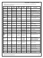
OPOS Controls for the devices listed in the table below are currently available and are operational under
Windows 2000 and Windows XP.
Device
Model
FJ
Model #
CashDrawer
(TP7K)
KD02909-7XXX
1.13
Power (FJ)
(TP7K)
KD02909-7XXX
1.13
Not supported on Axxx
FJ Thermal
KD02909-66XX
CT11
1.13
Single Station Receipt USB/HID
KD02909-66XX
CT11
1.13
Cash Drawer – 1 Station Printer
USB/HID
Printer
CashDrawer
FJ
FFNA
Model
Service
Object
OPOS
Version
Description
VDF
FJ VFD
Display
KD02909-902X
VF70 & VF35
1.13
Fujitsu 2-Line Display USB/HID
Keyboard
(MSR)
TeamMSR
KD02909-67XX
TeamMSR
(TeamKeyPad
MSR)
1.13
Fujitsu MSR USB/HID
(TP3K)
KD03207-C310
FjCDrwSO.dll
1.9
Access via COM10, (1 or 2
drawers)
(TP3K)
N/A
FjPowSO.dll
1.9
Access via COM30
(TP2K)
F7514DR11
Fjmcpso.dll
1.10
Access via the TeamCOM at
COM10, (1 or 2 drawers)
Power (FJ)
(TP2K)
N/A
Fjmcpso.dll
N/A
Multi Comm. Port board
Printer
FJ Thermal
CT10
FjUPrt1SO.dll
FjUPrt1PO.exe
1.9
1 Station, Rcpt
40 Col. Thermal
CT10
FjUPrDwSO.dll
FjUPrt1PO.exe
1.9
Cash Drawer - 1 Station Printer
CashDrawer
Power (FJ)
CashDrawer
CashDrawer
VFD
KD02906-1200
FJ
TP15
TP10
FJ VFD
Display
KD02906-1501
VF60
FjEVFDSO.dll
1.9
Fujitsu 2-Line Display
D22/25 MSR
D22/25 Lock
KD02906-????
D22/25
MSR/Lock
FjPOSKbPO.exe
FjPOSkbSO.dll
1.9
D22/25 MSR and Lock only
1.10
FJ POS/PC
Updated 133PQ keyboard
Firmware is required for WinNT
4.0 (SP3 or later required) or
later versions of Windows
Keyboard
(MSR,
Lock)
Keyboard
POS-PC
N/A
133PQ/104/32
fjkbdso.dll
fjklkso.dll
fjmsrso.dll
(fjkbd.dll)
fjtoneso.dll
Keyboard
92R/M/U
N/A
92R/M/U
FjRKbdSO.dll
FjRKbdPO.exe
1.10
92R/M/U Keyboard
Printer
FJ Dot Impact
F7514PR40
FD20
fjprtso.dll
1.3
2 ½ Station, R/J/S,
40 Col. Jour, 40 Slip
Printer
FJ Dot Impact
F7514PR70
FD21
fjprtso.dll
1.3
2 ½ Station, R/J/S,
40 Col. Jour, 70 Slip
Scanner/
Scale
FJ 9900/9950
Symphony
F7521E_S
9900/9950
1.10
Integrated Scanner/Scale
Scanner
SlimScan1200
F7521C
PB600064
fjscanso.dll
1.10
SlimScan Hand Held scanner
FJ VFD
Display
F7518CD
VF40/50
fjvfdso.dll
1.10
Fujitsu 2-Line Display
VFD
Fujitsu Frontech North America Inc.
fjsymphso.dll
Fjsymphpo.exe
12
Fujitsu OPOS 1.13 Configuration and Setup
1.3
Default Scanner and Scale Programming
The OPOS installer program stores a file called SCANNER-INIT.DOC in the install directory. This document
contains the default barcodes necessary to initialize Fujitsu’s SlimScan1200, and the 9900 scale for use with
FTXS OPOS drivers. Additional barcodes may need to be scanned if a 9900 scanner/scale is attached with a
single cable. This information is also included at the end of this document for convenience.
Scanner Notes
The FTXS OPOS 1.10 Scanner SO defaults are defined in the table below. To change the COM port, port
initialization string, and/or the terminator (end sentinel), the registry MUST be changed. Alternately, the scanners
can be reprogrammed to match the registry values. Fujitsu scanners may not necessarily be initialized to these
values and may require being initially programmed using programming barcodes.
COM
Port
Port
Initialization
String
End
Sentinel
Flow
Control
Enable
/Disable
Service Object
(DLL)
SlimScan 1200
COM4
9600,E,7,1
0x0D
CTS/RTS
No
Fjscanso.dll
Symphony 9900
COM1
9600,E,7,2
0x0D
CTS/RTS
Yes
FjsymphSO.dll
FjsymphPO.exe
Scanner Type
Note: The Scanner/Scale is only supported by the OPOS SO in the single-cable configuration in Magellan mode.
Fujitsu Frontech North America Inc.
13
Fujitsu OPOS 1.13 Configuration and Setup
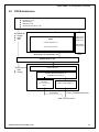
2.0
OPOS Architecture
Application
Double byte code
Multi Barcode
Multi Item code
Extended Printer Error Code
OPOS Device Framework
Direct Win32 API
Display
KBD
Misc.
RAFT
Fujitsu Retail
Application
Framework
OPOS
Control Objects (CO)
ARTS/POS
Business Rules
Service Objects (SO)
Win32 API (File I/O, multithreading, etc)
LAN DB
Win2000/Windows XP
System Devices
KBD
Display
Driver Interface
Standard Win2000/Windows XP
32-Bit RS 232 Port Driver
I/O Board
(24V/12V/5V Power)
COMxx
COM1, COM2 (IRQ 4,3)
Power/Data
Power (TeamPoS 3000) /Data
.... USB / RS 232 Devices….
Fujitsu Frontech North America Inc.
14
Fujitsu OPOS 1.13 Configuration and Setup
3.0
Hardware/Software Interface
3.1
Driver Registration
The OPOS drivers are registered automatically by the FJ install utility. Use Regedit.exe to browse and make
registry changes. The FTXS OPOS device registry information is located at:
HKEY_LOCAL_MACHINE\SOFTWARE\OleforRetail\ServiceOPOS.
3.1.1 USB Virtual COM (VCOM) Port Installation
USB and VCOM port drivers are installed in other installation processes. These drivers may be pre-installed or if
needed are provided on the FTXS OPOS web page.
3.2
TeamPoS 3600
Standard Serial:
COM1:
Port 1
COM2:
Port 2
COM3:
Port 3
COM4:
Port 4
On the motherboard
Legacy I/O Option
Legacy I/O Option
Legacy I/O Option
VCOM(SOL)
COM5:
Port 5
Fujitsu Frontech North America Inc.
Intel® Active Management Technology - Serial Over LAN
15
Fujitsu OPOS 1.13 Configuration and Setup
VCOM(Bridge)
COM10:
Cash Drawer (Optional) Silicon Labs CP2102 USB to UART Bridge
VCOM (USB):
COM33
COM37
COM42:
COM46:
CT10 – Fujitsu Single Station Printer
D22/25 MSR, Key Lock
USB VF60 - 2 (VFD2 driver maps USB port to COM port)
USB VF60 - 1 (VFD1 driver maps USB port to COM port)
3.3
TeamPoS 3000
3.3.1
Legacy Ports Board (TeamPoS 3000) Port Assignments
The legacy option provides both standard COM ports and virtual COM (VCOM) ports. The following is the ports
configuration:
Standard Serial:
* COM3:
Port 3 (Printer)
* COM4:
Port 4
* COM5:
Port 5
* COM6:
Port 6
* COM7:
Port 7
IRQ 5, Port Addr = 3E8h – 3EFh
IRQ 7, Port Addr = 2E8h – 2EFh
PCI Communications Port
PCI Communications Port
PCI Communications Port
VCOM (GPIO):
* COM10:
Cash Drawer
* COM30:
Power Management
VCOM (USB):
* COM33
* COM37
* COM42:
* COM46:
3.3.2
CT10 – Fujitsu Single Station Printer
D22/25 MSR, Key Lock
USB VF60 - 2 (VFD2 driver maps USB port to COM port)
USB VF60 - 1 (VFD1 driver maps USB port to COM port)
USB Option Board (TeamPoS 3000) Port Assignments
Fujitsu Frontech North America Inc.
16
Fujitsu OPOS 1.13 Configuration and Setup
The USB option provides virtual COM (VCOM) ports. The following is the ports configuration:
VCOM (GPIO):
* COM10:
Cash Drawer
* COM30:
Power Management
VCOM (USB):
* COM33
* COM37
* COM42:
* COM46:
CT10 – Fujitsu Single Station Printer
D22/25 MSR, Key Lock
USB VF60 - 2 (VFD2 driver maps USB port to COM port)
USB VF60 - 1 (VFD1 driver maps USB port to COM port)
3.4
TeamPoS 2000
3.4.1
TeamCOM (TeamPoS 2000) COM Port IRQ and IO Addresses
The FTXS install utility automatically adds the COM port information to the system registry. The COM ports are
configured as follows:
If the base address jumper is 230h (default for TeamPoS 5000, option for TeamPoS 2000):
*
*
*
*
*
*
*
*
COM3:
COM4:
COM5:
COM6:
COM7:
COM8:
COM9:
COM10:
Printer Port
Port 1
Port 2
Port 3
Port 4
Port 5
Port 6
Cash Drawer
IRQ 5, Port Addr = 230h – 237h
IRQ 5, Port Addr = 238h – 23Fh
IRQ 5, Port Addr = 240h – 247h
IRQ 5, Port Addr = 248h – 24Fh
IRQ 5, Port Addr = 250h – 257h
IRQ 5, Port Addr = 258h – 25Fh
IRQ 5, Port Addr = 260h – 267h
IRQ 5, Port Addr = 268h – 26Fh
If the base address jumper is 100h (default for TeamPoS 2000, option for TeamPoS 5000):
*
*
*
*
*
*
*
*
3.4.2
COM3:
COM4:
COM5:
COM6:
COM7:
COM8:
COM9:
COM10:
Printer Port
Port 1
Port 2
Port 3
Port 4
Port 5
Port 6
Cash Drawer
IRQ 5, Port Addr = 100h – 107h
IRQ 5, Port Addr = 108h – 10Fh
IRQ 5, Port Addr = 110h – 117h
IRQ 5, Port Addr = 118h – 11Fh
IRQ 5, Port Addr = 120h – 127h
IRQ 5, Port Addr = 128h – 12Fh
IRQ 5, Port Addr = 130h – 137h
IRQ 5, Port Addr = 138h – 13Fh
TeamCOMBO (TeamPoS 2000) COM Port IRQ and IO Addresses
The FTXS install utility automatically adds the COM port information to the system registry. The COM ports are
configured as follows:
If the base address jumper is 230h (option for TeamPoS 2000):
*
*
*
*
*
COM3:
COM4:
COM5:
COM6:
COM10:
Port 1
Port 2
Port 3
Port 4
Cash Drawer
IRQ 5, Port Addr = 230h – 237h
IRQ 5, Port Addr = 238h – 23Fh
IRQ 5, Port Addr = 240h – 247h
IRQ 5, Port Addr = 248h – 24Fh
IRQ 5, Port Addr = 268h – 26Fh
If the base address jumper is 100h (default for TeamPoS 2000):
*
*
*
COM3:
COM4:
COM5:
Port 1
Port 2
Port 3
Fujitsu Frontech North America Inc.
IRQ 5, Port Addr = 100h – 107h
IRQ 5, Port Addr = 108h – 10Fh
IRQ 5, Port Addr = 110h – 117h
17
Fujitsu OPOS 1.13 Configuration and Setup
*
*
COM6:
COM10:
Port 4
Cash Drawer
Fujitsu Frontech North America Inc.
IRQ 5, Port Addr = 118h – 11Fh
IRQ 5, Port Addr = 138h – 13Fh
18
Fujitsu OPOS 1.13 Configuration and Setup
3.4.3
TeamUSB (TeamPoS 2000) Virtual COM Port Assignments
VCOM drivers are installed that map certain USB devices to virtual COM ports, allowing the existing OPOS
service objects to run. The following are the default assignments:
*
*
*
*
COM7:
COM8:
COM3:
COM10:
USB VFD 1 (VFD1 driver maps USB port to COM port)
USB VFD 2 (VFD2 driver maps USB port to COM port)
USB 92U Keyboard/Key Lock/MSR/Line Display/Tone Indicator
Cash Drawer; Power Management
Fujitsu Frontech North America Inc.
19
Fujitsu OPOS 1.13 Configuration and Setup
3.5
COM Port Registry Setup (TeamPoS 2000) for Win2000/Windows XP
3.5.1
TeamCOM COM Port Settings (7 RS 232 Ports)
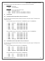
The COM port configurations are setup automatically in the Win2000/Windows XP registry in
HKEY_LOCAL_MACHINE\SYSTEM\CurrentControlSet\Services\Serial\Parameters\ Serial10000 Serial10007 by the install utility. The COM port registry settings are as follows if the base address jumper is set to
230h (PNT230.reg):
"PortAddress"=dword:00000230
"ForceFifoEnable"=dword:00000001
"DosDevices"="COM3"
"Interrupt"=dword:00000005
"InterruptStatus"=dword:00000270
"PortIndex"=dword:00000001
"Indexed"=dword:00000001
"PortAddress"=dword:00000250
"ForceFifoEnable"=dword:00000001
"DosDevices"="COM7"
"Interrupt"=dword:00000005
"InterruptStatus"=dword:00000270
"PortIndex"=dword:00000005
"Indexed"=dword:00000001
"PortAddress"=dword:00000238
"ForceFifoEnable"=dword:00000001
"DosDevices"="COM4"
"Interrupt"=dword:00000005
"InterruptStatus"=dword:00000270
"PortIndex"=dword:00000002
"Indexed"=dword:00000001
"PortAddress"=dword:00000258
"ForceFifoEnable"=dword:00000001
"DosDevices"="COM8"
"Interrupt"=dword:00000005
"InterruptStatus"=dword:00000270
"PortIndex"=dword:00000006
"Indexed"=dword:00000001
"PortAddress"=dword:00000240
"ForceFifoEnable"=dword:00000001
"DosDevices"="COM5"
"Interrupt"=dword:00000005
"InterruptStatus"=dword:00000270
"PortIndex"=dword:00000003
"Indexed"=dword:00000001
"PortAddress"=dword:00000260
"ForceFifoEnable"=dword:00000001
"DosDevices"="COM9"
"Interrupt"=dword:00000005
"InterruptStatus"=dword:00000270
"PortIndex"=dword:00000007
"Indexed"=dword:00000001
"PortAddress"=dword:00000248
"ForceFifoEnable"=dword:00000001
"DosDevices"="COM6"
"Interrupt"=dword:00000005
"InterruptStatus"=dword:00000270
"PortIndex"=dword:00000004
"Indexed"=dword:00000001
"PortAddress"=dword:00000268
"ForceFifoEnable"=dword:00000001
"DosDevices"="COM10"
"Interrupt"=dword:00000005
"InterruptStatus"=dword:00000270
"PortIndex"=dword:00000008
"Indexed"=dword:00000001
Fujitsu Frontech North America Inc.
20
Fujitsu OPOS 1.13 Configuration and Setup
The Win2000/Windows XP COM port registry settings are as follows if the base address jumper is set to 100h
(PNT100.reg):
"PortAddress"=dword:00000100
"ForceFifoEnable"=dword:00000001
"DosDevices"="COM3"
"Interrupt"=dword:00000005
"InterruptStatus"=dword:00000140
"PortIndex"=dword:00000001
"Indexed"=dword:00000001
"PortAddress"=dword:00000120
"ForceFifoEnable"=dword:00000001
"DosDevices"="COM7"
"Interrupt"=dword:00000005
"InterruptStatus"=dword:00000140
"PortIndex"=dword:00000005
"Indexed"=dword:00000001
"PortAddress"=dword:00000108
"ForceFifoEnable"=dword:00000001
"DosDevices"="COM4"
"Interrupt"=dword:00000005
"InterruptStatus"=dword:00000140
"PortIndex"=dword:00000002
"Indexed"=dword:00000001
"PortAddress"=dword:00000128
"ForceFifoEnable"=dword:00000001
"DosDevices"="COM8"
"Interrupt"=dword:00000005
"InterruptStatus"=dword:00000140
"PortIndex"=dword:00000006
"Indexed"=dword:00000001
"PortAddress"=dword:00000110
"ForceFifoEnable"=dword:00000001
"DosDevices"="COM5"
"Interrupt"=dword:00000005
"InterruptStatus"=dword:00000140
"PortIndex"=dword:00000003
"Indexed"=dword:00000001
"PortAddress"=dword:00000130
"ForceFifoEnable"=dword:00000001
"DosDevices"="COM9"
"Interrupt"=dword:00000005
"InterruptStatus"=dword:00000140
"PortIndex"=dword:00000007
"Indexed"=dword:00000001
"PortAddress"=dword:00000118
"ForceFifoEnable"=dword:00000001
"DosDevices"="COM6"
"Interrupt"=dword:00000005
"InterruptStatus"=dword:00000140
"PortIndex"=dword:00000004
"Indexed"=dword:00000001
"PortAddress"=dword:00000138
"ForceFifoEnable"=dword:00000001
"DosDevices"="COM10"
"Interrupt"=dword:00000005
"InterruptStatus"=dword:00000140
"PortIndex"=dword:00000008
"Indexed"=dword:00000001
Fujitsu Frontech North America Inc.
21
Fujitsu OPOS 1.13 Configuration and Setup
3.5.2
TeamCOMBO (TeamPoS 2000) COM Port Settings (4 RS 232 Ports)
The COM port configurations are setup automatically in the Win2000/Windows XP registry in
HKEY_LOCAL_MACHINE\SYSTEM\CurrentControlSet\Services\Serial\Parameters\ Serial10000 Serial10004 by the install utility. The COM port registry settings are as follows if the base address jumper is set to
230h (UNT230.reg):
"PortAddress"=dword:00000230
"ForceFifoEnable"=dword:00000001
"DosDevices"="COM3"
"Interrupt"=dword:00000005
"InterruptStatus"=dword:00000270
"PortIndex"=dword:00000001
"Indexed"=dword:00000001
"PortAddress"=dword:00000238
"ForceFifoEnable"=dword:00000001
"DosDevices"="COM4"
"Interrupt"=dword:00000005
"InterruptStatus"=dword:00000270
"PortIndex"=dword:00000002
"Indexed"=dword:00000001
"PortAddress"=dword:00000240
"ForceFifoEnable"=dword:00000001
"DosDevices"="COM5"
"Interrupt"=dword:00000005
"InterruptStatus"=dword:00000270
"PortIndex"=dword:00000003
"Indexed"=dword:00000001
"PortAddress"=dword:00000248
"ForceFifoEnable"=dword:00000001
"DosDevices"="COM6"
"Interrupt"=dword:00000005
"InterruptStatus"=dword:00000270
"PortIndex"=dword:00000004
"Indexed"=dword:00000001
"PortAddress"=dword:00000268
"ForceFifoEnable"=dword:00000001
"DosDevices"="COM10"
"Interrupt"=dword:00000005
"InterruptStatus"=dword:00000270
"PortIndex"=dword:00000008
"Indexed"=dword:00000001
The Win2000/Windows XP COM port registry settings are as follows if the base address jumper is set to 100h
(UNT100.reg):
"PortAddress"=dword:00000100
"ForceFifoEnable"=dword:00000001
"DosDevices"="COM3"
"Interrupt"=dword:00000005
"InterruptStatus"=dword:00000140
"PortIndex"=dword:00000001
"Indexed"=dword:00000001
"PortAddress"=dword:00000108
"ForceFifoEnable"=dword:00000001
"DosDevices"="COM4"
"Interrupt"=dword:00000005
"InterruptStatus"=dword:00000140
"PortIndex"=dword:00000002
"Indexed"=dword:00000001
"PortAddress"=dword:00000110
"ForceFifoEnable"=dword:00000001
"DosDevices"="COM5"
"Interrupt"=dword:00000005
"InterruptStatus"=dword:00000140
"PortIndex"=dword:00000003
"Indexed"=dword:00000001
Fujitsu Frontech North America Inc.
"PortAddress"=dword:00000118
"ForceFifoEnable"=dword:00000001
"DosDevices"="COM6"
"Interrupt"=dword:00000005
"InterruptStatus"=dword:00000140
"PortIndex"=dword:00000004
"Indexed"=dword:00000001
"PortAddress"=dword:00000138
"ForceFifoEnable"=dword:00000001
"DosDevices"="COM10"
"Interrupt"=dword:00000005
"InterruptStatus"=dword:00000140
"PortIndex"=dword:00000008
"Indexed"=dword:00000001
22
Fujitsu OPOS 1.10 Configuration and Setup
3.6
POS Key Scan Codes for 133PQ, 104 Key, and 32 Key Keyboards
POS keys are those keys, which are not normally recognized by Windows. These keys are not recognized because they don’t generate normal “make and break”
sequences.
The 133PQ device install will support the 133PQ, 104 Key, and 32 Key keyboards and attached devices (Key lock, Tone Indicator and the MSR).
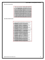
3.6.1
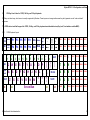
133PQ Keyboard Layout
SYS
REQ
Pause
F1
F3
F5
F7
ESC
Scroll
Lock
F2
F4
F6
F8 F10
~
`
TAB
Caps
Lock
Shift
Ctrl
!
1
@
2
Q W
A
S
Z
X
#
3
$
4
E
R
D
%
5
T
F
C
Alt
Fujitsu Frontech North America Inc.
F9
^
6
&
7
Y
U
G
V
H
B
Home
Page
up
Del End
Page
down
Ins
*
8
I
J
N
(
9
)
0
O
P
K
M
SPACE BAR
_
{
[
:
;
L
<
,
Gray
-
>
.
Gray
+
+
=
}
]
"
'
?
/
Alt
BKSP
|
\
POS1
POS2
POS3
POS8
POS9
POS10 POS11 POS12 POS13 POS14
POS15 POS16
POS4
POS5
POS6
POS7
/
POS17 POS18 POS19 POS20
7
8
9
POS21 POS22 POS23 POS24
ENTER
4
5
6
POS25 POS26 POS27 POS28
Shift
1
2
3
POS29 POS30 POS31 POS32
POS33
0
Ctrl
POS34 POS35 POS36 POS37 POS38
23
Fujitsu OPOS 1.10 Configuration and Setup
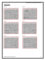
3.6.2
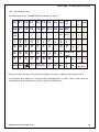
104 Keyboard Layout
The default layout for the TeamPoS 2000 104 keyboard is as follows:
F4
F5
F6 Ins
Page
up
_
-
+
=
BKSP
Page
down
7
8
9
POS1
POS2
4
5
6
(
9
)
0
1
2
3
POS3
0
.
POS5
POS6
POS8
POS9
ESC F1
F2
F3
TAB F7
F8
F9 F10 F11 F12 Del End
Home
|
\
{
[
}
]
?
/
:
;
!
1
~
`
@
2
#
3
$
4
%
5
^
6
&
7
"
'
*
8
Q
W
E
R
T
Y
U
I
O
P
A
S
D
F
G
H
J
K
L
ENTER
Z
X
C
V
B
N
M
<
,
>
.
Alt
SPACE Alt Ctrl
Caps
Lock
Shift Ctrl
POS7
POS
ENTER
Rows are labeled A through H and columns are numbered 1 through 13, starting at the bottom left corner.
In this particular layout POS4 (C11) is used to widen the standard Enter key, POS 11 (A05) is used to widen the
standard Space bar and POS10 (A12) is used to widen the POS Enter key.
Fujitsu Frontech North America Inc.
24
Fujitsu OPOS 1.13 Configuration and Setup
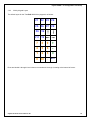
3.6.3
32-Key Keypad Layout
The default layout for the TeamPoS 2000 32-key keypad is as follows:
F1
F2
F3
F4
F5
F6
F7
F8
F9 F10
F11 F12
7
8
9
+
4
5
6
-
1
2
3
=
0 00
.
ENTER
Rows are labeled A through H and columns are numbered 1 through 4, starting at the bottom left corner
Fujitsu Frontech North America Inc.
25
Fujitsu OPOS 1.13 Configuration and Setup
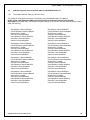
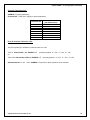
The OPOS driver returns key values for the 133PQ 38-POS keys as specified in the Windows registry. During the
OPOS installation these values default to:
"POSKey01"=dword:000007d1
"POSKey02"=dword:000007d2
"POSKey03"=dword:000007d3
"POSKey04"=dword:000007d4
"POSKey05"=dword:000007d5
"POSKey06"=dword:000007d6
"POSKey07"=dword:000007d7
"POSKey08"=dword:000007d8
"POSKey09"=dword:000007d9
"POSKey10"=dword:000007da
"POSKey11"=dword:000007db
"POSKey12"=dword:000007dc
"POSKey13"=dword:000007dd
"POSKey14"=dword:000007de
"POSKey15"=dword:000007df
"POSKey16"=dword:000007e0
"POSKey17"=dword:000007e1
"POSKey18"=dword:000007e2
"POSKey19"=dword:000007e3
"POSKey20"=dword:000007e4
"POSKey21"=dword:000007e5
"POSKey22"=dword:000007e6
"POSKey23"=dword:000007e7
"POSKey24"=dword:000007e8
"POSKey25"=dword:000007e9
"POSKey26"=dword:000007ea
"POSKey27"=dword:000007eb
"POSKey28"=dword:000007ec
"POSKey29"=dword:000007ed
"POSKey30"=dword:000007ee
"POSKey31"=dword:000007ef
"POSKey32"=dword:000007f0
"POSKey33"=dword:000007f1
"POSKey34"=dword:000007f2
"POSKey35"=dword:000007f3
"POSKey36"=dword:000007f4
"POSKey37"=dword:000007f5
"POSKey38"=dword:000007f6
These hex values correspond to the decimal values in the range 2001 through 2038.
For the 104 keyboard, keys can be mapped as POS keys using the KEYMAP utility. The mapping values that
correspond to POSKey01 through POSKey38 above are set in the mapping program by selecting the values in
the ranges A-Z and F1-F12 and checking both the Attribute boxes "Returns Break code only" and "Prefix code
add".
Fujitsu Frontech North America Inc.
26
Fujitsu OPOS 1.13 Configuration and Setup
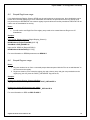
3.7
OPOS MSR Track Configurations for 133PQ, 104 and 32-Key Keyboards
The Fujitsu Keyboards may have MSR devices included. These MSR devices are available in several
configurations. To insure the proper desired operation, the following registry entry may need to be changed to
match the actual MSR type installed in the keyboard and enable reading of the desired track(s). Only the tracks
defined by MSRType are enabled in these keyboards.
HKEY_LOCAL_MACHINE\SOFTWARE\OLEforRetail\ServiceOPOS\MSR\fjmsrso
String Value “MSRType” can have one of the following values:
ISO12
ISO23
ISO123
ISO12JIS2
Other
3.8
- Track 1 & 2 Reader
- Track 2 & 3 Reader
- Track 1, 2, & 3 Reader
- Track 1, 2 ISO and Track 2 JIS Reader
- JIS Track 1 & 2 Reader
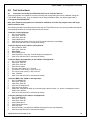
OPOS Test Utilities
The FJ OPOS device test utilities are installed in the directory selected at installation. The following shows the
supported Fujitsu peripherals, their corresponding test utility names, and the default SO name used by the test
program OPEN button command if no data is entered:
Device Class
Common Control Test Program Name
CashDrawer
CCOcd.exe
POSPower
CCOPwr.exe
FjPowerSupplyUnit
Fjpower.exe
CashDrawer
CCOcd.exe
LineDisplay
CCOvfd.exe
MSR
CCOmsr.exe
Keylock
CCOkeyl.exe
CashDrawer
CCOprt.exe
POSPrinter
CCOcd.exe
MICR
CCOMicr.exe
POSKeyboard
CCOkbd.exe
Scale
CCOscale.exe
Scanner
CCOscan.exe
ToneIndicator:
CCOtone.exe
Note: The 133PQ tests also work on the 104P devices.
Fujitsu Frontech North America Inc.
27
Fujitsu OPOS 1.13 Configuration and Setup
See Section 6 for instructions regarding the running of these test programs.
Also provided is a single test utility (FjOposTest.Exe) that displays a button for each OPOS device found in the
registry and provides a test for most of the basic devices (cash drawer, printer, MICR, MSR, scanner, scale,
keyboard, key lock, line display, tone indicator, and FJ Power). If a device is selected for which no test is
available, a “Not Supported” message is displayed. This utility provides a basic installation and configuration
validation.
3.9
Microsoft Runtime Support Files
A number of Microsoft Visual C++ and Visual Basic runtime libraries are needed for the execution of the OPOS
environment. These files are listed below. They are copied to the following directories during installation if
needed:
Win2000
Windows XP
- WinNT\System32
- Windows\System32
COMDLG32.ocx
MFC42u.dll
MSVCRT40.dll
COMCTL32.ocx
MSVBVM50.dll
OLEAUT32.dll
Asycfilt.dll
MSVCIRT.dll
OLEPRO32.dll
COMCAT.dll
MSVCP50.dll
STDOLE2.tlb
Ctl3D32.dll
MSVCRT.dll
MFC42.dll
MSVCRT20.dll
NOTE: The Microsoft runtime modules above are from Microsoft Visual Studio 6.0 Service Pack 5 or later.
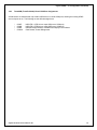
NOTE: Microsoft’s 2010 Redistributable package is installed if any of the TeamPoS 7000 devices (OPOS version
1.13 Services) are installed.
Fujitsu Frontech North America Inc.
28
Fujitsu OPOS 1.13 Configuration and Setup
4.0
TeamPoS Hardware Setup
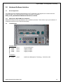
4.1
TeamPoS 3600 and TeamPoS 3000
12V Retail USB Connector
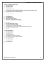
4.1.1
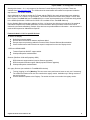
24V Retail USB Connector
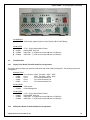
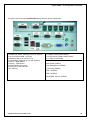
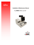
Legacy Interface Option
The figure below shows the TeamPoS 3600 Legacy Interface Option:
The Legacy board contains six jumpers. Three of the jumpers (CN7, CN8, & CN9) will either
provide +5 V on pin 9 of DB9 connector or provide the RI signal on that pin. Default is set as RI on
that pin. Jumpers CN4, CN5, and CN6 enable the DCD signal on pin 1 of the DB9 connector and
should remain in this default position.
Fujitsu Frontech North America Inc.
29
Fujitsu OPOS 1.13 Configuration and Setup
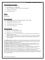
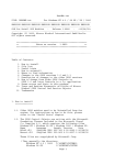
The figure below shows the TeamPoS 3000 legacy Interface Option configuration:
Standard Ports
2x COM Ports (COM1, COM2) [5V and 12V optional]
1x 24 Volt Powered USB – for Printer
4x Standard USB, 2x in front 2x in rear
1x Cash Drawer (Supports up to 2 cash Drawers)
1x DVI-D – Digital Monitor
1x Analog – VGA Monitor
2x PS/2 keyboard and mouse
2x Audio, Mic In and Audio Out
LAN - Ethernet
Legacy Interface Option
2 x 24VDC RS232 (COM3, COM7)
3 x 5 VDC RS232 (COM4, COM5, COM6)
6 x 12 VDC Powered USB
Cash Drawer (COM10)
Power Management (COM30)
CT10 Printer (COM33)
VF60-1 (COM46)
VF60-2 (COM42)
D22/25 MSR, Key lock (COM37)
Fujitsu Frontech North America Inc.
30
Fujitsu OPOS 1.13 Configuration and Setup
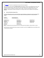
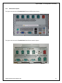
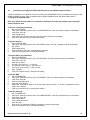
4.1.2
USB Interface Option
The figure below shows the TeamPoS 3600 Powered USB Interface Option:
The figure below shows the TeamPoS 3600 Cash Drawer Interface Option:
Fujitsu Frontech North America Inc.
31
Fujitsu OPOS 1.13 Configuration and Setup
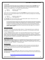
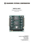
The figure below shows the TeamPoS 3000 USB configuration:
Standard Ports
2x COM Ports (COM1, COM2)
1x 24 Volt Powered USB – for Printer
4x Standard USB, 2x in front 2x in rear
1x Cash Drawer (Supports up to 2 cash Drawers)
1x DVI-D – Digital Monitor
1x Analog – VGA Monitor
2x PS/2 keyboard and mouse
2x Audio, Mic In and Audio Out
LAN - Ethernet
Option I: 3 x 12 Volt USB
Option II: 6 x 12 Volt USB
Cash Drawer (COM10)
Power Management (COM30)
Backplane jumpers to enable COM1, COM2 power:
JP4 (COM1) and JP5 (COM2) Jumper Settings:
1–2
3–4
5–6
RI
5V
12V
(Standard COM)
(Powered COM)
(Powered COM)
Fujitsu Frontech North America Inc.
32
Fujitsu OPOS 1.13 Configuration and Setup
4.2
TeamPoS 2000
There are three different configurations for the TeamPoS I/O Boards: TeamCOM (7 Rs232 Ports), TeamCOMBO
(4 Rs232 and 4 USB Ports) and TeamUSB (7 USB Ports).
TeamCOM ports and standard PC COM ports do not use the same naming convention. The silk-screened
numbers on the TeamCOM board refer to an ordinal that is not related to more familiar COM port names. COM1
and COM2 are always the standard PC motherboard ports. TeamCOM Port0 is silk screened as PTR and is
COM3, Port1 is COM4, Port2 is COM5, and so on. DRW is attached to COM10. The following table shows the
relationship between Windows COM ports and TeamCOM port naming conventions along with other details.
Connector
Power
Typical Use
WINDOWS
COM Port #
Interrupt
I/O Address
Port 0
D15 F/M
Port 1
D9
MALE
5V
+5V
+12V
+24V 12V
Printer Scanner
COM 3
Port 2
D9
MALE
5V
Port 3
D9 F/M
Port 4
D9 F/M
5V - 24V 5V - 24V
VFD1
Cust.
Port 5
D9
MALE
5V
Port 6
D9 F/M
Port 7
Internal
5V - 24V
VFD2
(OP)
92R/M/U
COM 4
COM 5 COM 6 COM 7 COM 8 COM 9 COM 10
5, 7, 9, 10, 11 and 12 Switch Selectable
100/230 108/238 110/240 118/248 120/250 128/258 130/260 138/268
TeamCOM Interrupts & I/O Addresses (Interrupt selectable by jumper)
4.2.1 OPOS 1.10 Installation Notes
* The current default port assignments for the TeamCOM Board are:
* Scanner
= COM4
* Line Display 1
= COM6 (VF40/50 Serial)
* Line Display 2
= COM7 (VF40/50 Serial)
* Printer
= COM3
* Scanner/Scale
= COM1
* 92R/M/U Keyboard = COM7 (Serial)
* Cash Drawer
= COM10 (internal)
*
The current default port assignments for the TeamCOMBO Board are:
* Scanner
= COM3
* Line Display 1
= COM5 (VF40/50 Serial)
* Line Display 2
= COM6 (VF40/50 Serial)
* Line Display 1
= COM7 (VF50 USB)
* Line Display 2
= COM8 (VF50 USB)
* Printer
= Retail USB
* Scanner/Scale
= COM1
* 92R/M/U Keyboard = COM6 (Serial)
* 92R/M/U Keyboard = COM7 (USB)
* Cash Drawer
= COM10 (internal)
*
The current default port assignments for the TeamUSB Board are:
* Scanner
= COM1 or COM2 (requires external power)
Fujitsu Frontech North America Inc.
33
Fujitsu OPOS 1.13 Configuration and Setup
*
*
*
*
*
*
Line Display 1
Line Display 2
Printer
Scanner/Scale
92U Keyboard
Cash Drawer
= COM7 (VF50 USB)
= COM8 (VF50 USB)
= Retail USB
= COM1 or COM2
= COM3 (USB)
= COM10 (internal)
Additional Notes:
The port assignments may be changed using the Install utility or Regedit.exe. The registry path for
the OPOS devices is: HKEY_LOCAL_MACHINE\SOFTWARE\OLEforRetail\ServiceOPOS\{OPOS
device\FJ device}
The Virtual COMM ports used for the USB devices can be changed by using the Device Manager and
right clicking the port that is to change and select Properties. Select the Port Settings tab then
select the Advanced… button. Use the COMM Port Number dropdown to change the port. Set the
corresponding port in the registry entry for the device.
TeamCOMBO - 92U (USB) and Line Display 1 (VF50U –USB) COMM port conflict. If these devices
are used together – use the procedure above to reassign the COM port of one of the devices.
An Error 104 on “Open” usually indicates incorrect port assignment or device not connected (no CTS)
Use the supplied test utilities for initial test/diagnostics. See Section 6 for instructions regarding the
running of these test programs.
Fujitsu Frontech North America Inc.
34
Fujitsu OPOS 1.13 Configuration and Setup
4.2.2
TeamCOM (7 RS232 Ports) Board Setup for TeamPOS 2000
The TeamCOM version of the I/O Board provides seven (7) powered RS232 serial ports with optional jumper
selected power distribution. The I/O Board also includes a microprocessor controlled External Control Interface to
monitor and control external functions that are specific to the TeamPoS 2000.
The External Control Interface supports monitoring and control of the following units:
PSU (Power Supply Unit)
Dual Cash Drawers
CMOS (Optional)
Front Panel LEDs
All communications between the External Control Interface and the PoS terminal hardware and software are
through standard PoS terminal compatible serial ports using a 16C550 UART or virtual com port (VCP) device.
This hardware is recognized and supported by standard drivers supplied with the various Windows operating
systems. The ability to use standard drivers supplied with the operating systems greatly simplifies development
needed to support TeamPoS 2000 specific functionality and allows easy migration to new versions of operating
system software.
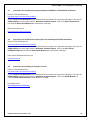
The following diagram is a representation of the rear panel of the TeamCOM board showing the various
connector locations.
1
3
5
Cash Drawer
LCD Power
POS Printer
2
4
6
RS232 Port Assignments:
*
*
*
*
*
*
*
*
Printer Port
Port 1
Port 2
Port 3
Port 4
Port 5
Port 6
Cash Drawer
COM3: (24V)
COM4: (5V)
COM5: (5V)
COM6: (24V)
COM7: (24V)
COM8: (5V)
COM9: (24V)
COM10: (internal)
Fujitsu Frontech North America Inc.
35
Fujitsu OPOS 1.13 Configuration and Setup
The following switches are shown viewed with the TeamCOM board above the motherboard with the TeamPoS
2000 chassis side panel removed:
TeamCOM Board Setup for TeamPoS 2000
Port 1:2
87654321
xx xx
87654321
FJ(FD21) ESC/POS
7654321 7654321
xxxxxxx
7654321 7654321
MISC
87654321
vvvv
87654321
IRQ
87654321
x
87654321
Switch Setting Legend (Default Settings in Bold):
Port 1: 2
8=Port2
DC Power on Pin 9
7=Port2
DC Power on Pin 9
6=Port2
Standard RS232
5=Port2
Standard RS232
4=Port1
DC Power on Pin 9
3=Port1
DC Power on Pin 9
2=Port1
Standard RS232
1=Port1
Standard RS232
FJ FD21
1234567
ESC/POS
1234567
; all jumpered for ESC/POS printer as default
MISC/SW 3
8=on=FAN3 ON
7=on=FAN2 ON
6=on=FAN1 ON
5=on=BATTERY ENABLED
4=off=COM3/4 or MULTI
3=off=OPC or MCP
2=off=OPC 278 or 378
1=off=UART 230 or 100
ISAIRQ, on some boards this switch is labeled SW 4
8=IRQ5
7=IRQ7
6=IRQ9
5=IRQ10
4=IRQ11
3=IRQ12
2=VFD, ESC interface/FJ interface OFF
1=RESET, ENA/Disable
Note: TeamPoS 2000 TeamCOM board USES IRQ 5. The BIOS must be configured with IRQ5 reserved as a
“LEGACY DEVICE”; otherwise Plug-and-Play operating systems will not assign the TeamCOM IRQ correctly.
This is the default BIOS setting as shipped from Fujitsu.
Fujitsu Frontech North America Inc.
36
Fujitsu OPOS 1.13 Configuration and Setup
4.2.3
TeamCOMBO (4 RS232 / 4 USB Ports) Board Setup for TeamPoS 2000
The TeamCOMBO board is differentiated from the TeamCOM board by fewer serial ports, (4 vs. 7) and the
addition of a 4 port Retail USB Hub. Serial ports 1-4 are implemented on this version of the I/O board. See
functional block diagram for details. Serial port interrupts can be selected by using jumper CN2009 and can be set
to IRQ 5,7,9,10,11 & 12.
Serial Ports 1 & 2, CN5279, may be powered with 5V, the default setting, by plugging jumpers into JP1 as
indicated on the schematic. Either or both of these serial ports may be reconfigured to be a standard serial port by
installing the appropriate jumpers. Note that 5V optionally applied to Serial Ports 1 & 2 appear on pin 6 of the DB9
connector.
The permanently powered serial ports (3 & 4) have 24V on pin 4 of the DB9 connectors, CN5281, and 5V on pin
6. Power ground reference for serial ports 3 & 4 are pins 1 & 9 of CN5281, whereas logic ground reference is pin
5.
The TeamCOMBO Board features a 4-port USB Hub that differs from a conventional USB hub in that the
connectors are of a special type that provides power to specially designed USB retail peripherals. The standard
model has two 24V Retail USB ports and two 12v Retail USB ports.
The 24V and 12V USB powered connectors are shown below. Note the keying of these connectors as shown
below. Only peripheral connector cables that match the key may be attached.
12V Retail USB Connector
24V Retail USB Connector
The following diagram is a representation of the rear panel of the TeamCOMBO board showing the various
connector locations.
USB Ports
Serial Ports
1
3
LCD Power
Cash Drawer
2
4
RS232 Port Assignments:
Port 1 == COM3, IRQ 5, I/O 0x100, +5v, D-sub 9(M), usage is Scanner (also DOS COM3 port)
Port 2 == COM4, IRQ 5, I/O 0x108, +5v, D-sub 9(M), usage is open
Port 3 == COM5, IRQ 5, I/O 0x110, +24v, D-sub 9(F), usage is Line Display
Port 4 == COM6, IRQ 5, I/O 0x118, +24v, D-sub 9(F), usage is 92R/M/U keyboard (also DOS COM4 port)
DRW == COM10, IRQ 5, I/O 0x138, D-sub 9(F), usage is Cash Drawer; also the I/O interface used for the CMOS
& Fujitsu power.
Alternate I/O addresses start at 0x230, the same as for the current Retail I/O board.
Fujitsu Frontech North America Inc.
37
Fujitsu OPOS 1.13 Configuration and Setup
USB1 == 24v, usage is USB version of the Epson TM6000 printer
USB2 == 24v, usage is USB version of the Line Display
USB3 == 12v or 24v depending on TeamCOMBO board type
USB4 == 12v, usage is (future) USB version of the Symphony 9900 Scanner/Scale
The following switches are shown viewed on the TeamCOMBO I/O board above the motherboard with the
TeamPoS 2000 chassis side panel removed:
TeamCOMBO Board Setup for TeamPoS 2000
Port 1:2
87654321
xx xx
87654321
X = jumpered
SW3 MISC
87654321
vvvv
87654321
ISA/IRQ
87654321
v
87654321
v = ON position
Switch Setting Legend (Default Settings in Bold):
Port 1:2
8=Port2
DC Power on Pin 9
7=Port2
DC Power on Pin 9
6=Port2
Standard RS232
5=Port2
Standard RS232
4=Port1
DC Power on Pin 9
3=Port1
DC Power on Pin 9
2=Port1
Standard RS232
1=Port1
Standard RS232
MISC/SW 3
8 = on = FAN3 ON
7 = on = FAN2 ON
6 = on = FAN1 ON
5 = on = BATTERY ENABLED
4 = off = COM3/4 or MULTI
3 = off = NA
2 = off = NA
1 = off = UART 0230 or 0100
ISA/IRQ, on some boards this switch is labeled SW 4
8 = IRQ5
7 = IRQ7
6 = IRQ9
5 = IRQ10
4 = IRQ11
3 = IRQ12
2 = VFD, ESC interface/FJ interface OFF
1 = RESET, ENA/Disable
Note: TeamPoS 2000 Retail I/O board by default USES IRQ 5. The BIOS must be configured with IRQ5 reserved
as a “LEGACY DEVICE”; otherwise Plug-and-Play operating systems will not assign the Retail I/O IRQ correctly.
This is the default BIOS setting as shipped from Fujitsu.
Fujitsu Frontech North America Inc.
38
Fujitsu OPOS 1.13 Configuration and Setup
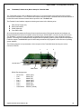
4.2.4
TeamUSB (7 USB Ports) Board Setup for TeamPoS 2000
The TeamUSB Board features a 7-port USB Hub that differs from a conventional USB hub in that the connectors
are of a special type that provides power to specially designed USB retail peripherals. The standard model has
four 24V Retail USB ports and three 12v Retail USB ports.
The 24V and 12V USB powered connectors are shown below. Note the keying of these connectors as shown
below. Only peripheral connector cables that match the key may be attached.
12V Retail USB Connector
24V Retail USB Connector
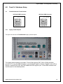
The following diagram is a representation of the rear panel of the TeamUSB board showing the various connector
locations.
12V
Powered USB
24V
Powered USB
LCD Power
USB 7
Fujitsu Frontech North America Inc.
Cash Drawer
USB 1
39
Fujitsu OPOS 1.13 Configuration and Setup
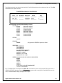
The following switch settings are shown viewed on the TeamUSB Board above the motherboard with the
TeamPoS 2000 chassis side panel removed.
TeamUSB Setup for TeamPoS 2000
SW1
1234
^^^^
1234
^ = on position
Team USB Switch Setting Legend (Default Settings in Bold):
SW1
1 = BATL
2 = FAN1
3 = FAN 2
4 = FAN 3
Detect Lead Acid Battery Alarm
Detect CPU Fan Alarm
Detect PSU Fan Alarm
Detect Chassis Fan Alarm
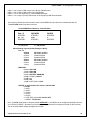
JP1
1-2
3-4
5-6
7-8
9-10
11-12
13-14
15-16
17-18
19-20
“M” Motherboard
OPEN
SHORT
OPEN
SHORT
OPEN
SHORT
SHORT
SHORT
SHORT
SHORT
ON/OFF
ON/OFF
ON/OFF
ON/OFF
“A” Motherboard
OPEN
OPEN
SHORT
OPEN
SHORT
OPEN
OPEN
OPEN
OPEN
OPEN
JP1 configures the TeamUSB board to use six or seven USB ports depending upon the motherboard being used.
JP2 – Cash Drawer – decodes each drawer open switch. Configures the type of cash drawer being used: Fujitsu
cash drawer or NCR, Fujitsu is the default.
JP2
1-2
3-4
5-6
7-8
9-10
Fujitsu
SHORT
OPEN
OPEN
OPEN
SHORT
NCR
OPEN
SHORT
SHORT
SHORT
OPEN
JP3 – Determines the power source for the 12V on USB port 6. Options are from 24V power through DC-DC
converter or directly from 12V power.
JP3 (USB 6 Power)
PSU-12V
DC-DC
1-2
SHORT
OPEN
3-4
SHORT
OPEN
5-6
OPEN
OPEN
7-8
OPEN
SHORT
9-10
OPEN
SHORT
Fujitsu Frontech North America Inc.
40
Fujitsu OPOS 1.13 Configuration and Setup
4.2.4.1 TeamUSB default port details:
USB1 == 24v, usage is USB version of the Epson TM-H6000 or TM-T88 printer
USB2 == 24v, usage is USB version of the Line Display
USB3 == 24v, usage is USB version of the 92U Keyboard/Key Lock/MSR/Line Display/Tone Indicator
USB4 == 24v,
USB5 == 12v, usage is (future) USB version of the Scanner/Scale
USB6 == 12v,
USB7 == 12v,
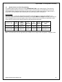
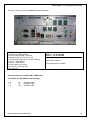
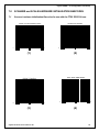
4.2.5
TeamCOM Board Setup for TeamPoS 5000
IRQ
MCP
Parallel Port
Comm. Port
Printer jumper (7)
4.5.1
5
0x230
0x378
MULTI
FJ (FD21) for Fujitsu printers,
ESC POS for all other vendor’s printers.
TeamCOM POS Printer Jumper Setup
The TeamCOM board supports two types of POS printers, the Fujitsu POS printer(s) and the ESC/POS printer.
The default POS printer jumper setting on the TeamCOM board is for the Fujitsu POS printer. The printer jumper
group (consisting of 7 jumpers) is located directly behind the COM3 port on the TeamCOM board. To switch to a
different POS printer type, change all 7 jumper settings from the 1-2 position (Fujitsu printer) to the 2-3 position
(ESC/POS printer) or vice versa. Verify printer type with the label next the jumper group.
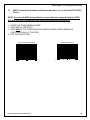
4.2.5.2 SMC Ethernet Card
Suggested setup, should be changed to fit individual requirements
I/O Address:
0x280
RAM Address:
0xD000
ROM Address:
0xDA00 or 0xDC00
IRQ:
10
4.2.5.3 3COM EtherLink III Card
Suggested setup, should be changed to fit individual requirements
Wake-Up ID Address: 0x150
I/O Address:
0x300
IRQ:
10
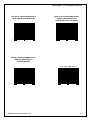
4.2.5.4 Sound Card
See note below on INTEL Motherboard
Port Address:
240
IRQ:
7
INTEL Motherboard
Onboard audio must be disabled through TeamPoS BIOS CMOS setup.
Fujitsu Frontech North America Inc.
41
Fujitsu OPOS 1.13 Configuration and Setup
5.0
Troubleshooting
5.1
Common Problems
1. D22 / D25 MSR “Open” returns 107 (No Hardware) error. Insure that the separate A to B USB cable is
connected to the LCD Unit. This MSR device does not use the powered USB cable for its USB or power
connection.
2. CT10 Printer Error Indicator stays ON. Insure that the FW switch 3-8 is set to “Closed”. Refer to the
Printer’s User’s Manual for the switch setting procedure. Later firmware releases will have this setting as the
default.
3. WinNT can't access TeamCOM ports. Verify that the TeamCOM RS232 ports can be accessed using the
WinNT Diagnostics. If COM1-10 are present under the RESOURCES tab, the TeamCOM board is probably
working. The most likely reason for failure is that the 100H/230H address selection jumper on the TeamCOM
board does not match what was installed. Otherwise check the on-board fuses on TeamCOM board. They are
socketed, and depending on the revision of board, there are either two or three fuses. The fuses may blow if
devices are plugged into the TeamCOM board while the TeamPoS is powered on. Please try to avoid doing
this! Also, ensure that the TeamCOM board MCP/OPC jumper is set to MCP mode.
4. OPOS Open error on TeamCOM port or MSR does not work. Ensure that the OPOS software installation
process is performed under a user that has Administrator privileges.
5. Printer Access Problems. Ensure that the printer jumper settings (one block of jumpers that has to be
changed as one) on the TeamCOM board are correctly positioned for either a Fujitsu printer or for an
ESC/POS type printer.
6. Keyboard access failure. If there is no access to the MSR, POS keys, or the key switch, ensure that the
keyboard has the correct keyboard controller chip. If running under WinNT 4.0 then Service Pack 3 must be
installed. Keyboards built prior to 11/97 will probably not work unless the keyboard controller chip is
updated. This is because the WinNT keyboard driver cannot send the necessary hex codes to enable and
run the MSR and other keyboard devices. If the failure persists, ensure the checksum label on the keyboard
controller chip (accessed by removing the bottom of keyboard) is 4684-031H. Verify that the “TYPE NO.” on
the bottom of the keyboard is PB600335 and not 53256.
7. MSR reads fail. Check keyboard controller chip inside the keyboard (see above). Check the three-position
switch setting in the keyboard where the MSR cover is and ensure it corresponds to the reader type (i.e. track
1/2 2/3 or JIS) installed in the keyboard compartment for the MSR reader. If so equipped, also ensure that the
keyboard type switch is set for US standard. (Setting this switch incorrectly will cause the BIOS to not detect a
keyboard).
8. 3COM port conflict. If the TeamCOM address jumper is set to 100H, make sure that the 3COM wake up port
address is set to 150H, using the 3COM utility dated 7-18-96. Then use REGEDIT
hkey_local_machine\system\currentcontrolset\elnk32\parameters, setting the value of
IDPORT:REG_DWORD:0x150. The standard wakeup port is 110H, this conflicts with the TeamCOM port
110H, when the base address is set to 100H. The preferred and recommended method is not to change
anything on the 3COM board, and change the base address of the TeamCOM board to 230H.
9. Cash drawer fails to open with the PAC2000 Motherboards (Only a few of these Motherboards were
ever shipped). The Cash Drawer is not usable in the OPOS environment when the TeamCOM jumper base
address is set to 230H.
10. COM5 usage causes failure of other TeamCOM ports. Incorrect registry information causes the COM5
conflict. An updated registration file is available that corrects this for TeamCOM base address 230H. The
current installation software available from the WEB corrects this problem.
Fujitsu Frontech North America Inc.
42
Fujitsu OPOS 1.13 Configuration and Setup
11. Numeric keypad key does not input numeric characters or the MSR does not work. Please choose the
initially opened device from among Keylock, MSR and POSKeyboard, and change the corresponding registry
entry “Ignore_Numlock” value to “F”. This is most often caused by a VB application issuing multiple
"SendKeys" commands. Refer to MSDN issue Q179987.
12. Additional OEM serial board/driver installation. Please install the other vendor's serial board and/or OPOS
drivers after the FTXS OPOS software installation.
13. CT10 Dual Cash Drawer. If both cash drawer are installed a registry entry under the CT10_CD1 and
CT10_CD2 “Status_Mode” with a value of “Invert” is added. This is needed along with special cables and
cash drawers. For a single drawer the value of “Status_Mode” is “Normal”. Note this is changed in versions
1.10.6 and later back to “Normal” – a Fujitsu cable for Fujitsu drawers (TP10 and TP15) is now
available. To use drawers with inverted status signals – change the registry value of “Status_Mode” to
“Invert”.
14. Epson OPOS Installation Fails on TeamPoS. Install the FTXS OPOS drivers first and then reboot to make
Windows aware of the TeamCOM comm. ports. Then run Epson’s installation program. The Epson installer
needlessly verifies for overlapping comm. port conflicts with other similar OPOS devices. The Epson installer
will fail if any other device such as another vendor’s printer was previously assigned to comm. port 3. The
same failure will occur if another vendor’s MICR was installed. To work around this problem, BEFORE
running Epson’s OPOS installer, run REGEDIT.EXE from a DOS prompt and delete the OPOS key for this
device type. For the printer, the registry key that should be deleted prior to running Epson’s installer is:
HKEY_LOCAL_MACHINE\SOFTWARE\OLEforRetail\ServiceOPOS\POSPrinter.
15. WinNT 4.0 Keyboard Driver and Firmware Dependency
For correct POS/PC Keyboard operations under WinNT 4.0, an updated keyboard driver for WinNT 4.0
and updated POS/PC keyboard firmware are required from Microsoft and Fujitsu respectively.
The required keyboard driver files are available in WinNT4.0 Service Pack #3 or later. The service pack is
available from Microsoft’s support website.
The upgraded FJ POS/PC Keyboard firmware can be obtained from the Fujitsu Product group or through
Fujitsu Customer Service.
5.2
3COM –TeamCOM Address Conflict
The following scenario applies to some older 3COM drivers for the 3C509B Ethernet adapter. The current driver is
available from the 3COM WEB site at http://www.3com.com, and is the recommended driver to be used.
Note: The FTXS OPOS install utility does not include the 3COM diagnostics and drivers. These files can be
downloaded from the 3COM WEB site. The following suggestions are for reference only. Please refer to 3COM
WEB site or contact 3COM for current technical information and driver updates.
In order to avoid conflicts with the 3COM card, the base address jumper for the TeamCOM board should be set to
230H. If the base address jumper is set to 100H, then the following options should be considered.
WinNT:
1. Verify Plug and Play is disabled on the 3COM card.
Power off; disconnect the data cable from the TeamCOM board.
Boot DOS, run 3COM setup utility 3C5X9CFG.EXE to disable the Plug and Play option on the 3COM
card. Verify the I/O address and IRQ setting. Exit the utility.
Power off and reconnect the data cable to the TeamCOM board.
2. The 3COM EtherLink driver (Elnk3.sys dated after 7-18-96) loaded by WinNT does not resolve the WakeUp address conflict. 3COM recommends the use of the version dated 7-18-96 as an interim solution. The
Fujitsu Frontech North America Inc.
43
Fujitsu OPOS 1.13 Configuration and Setup
driver can be downloaded from the 3COM web site (file name is 3C5X9X.EXE), explode the package and
copy the whole package on to a diskette. To install the driver:
Remove the 3COM adapter from Control Panel/Network/Adapter
Choose Add and Have Disk
Insert the diskette that contains the 3COM driver package.
3. The Wake-Up address for the 3COM LAN Adapter conflicts with the I/O address setting for one of the
COM ports on the TeamCOM board. The 3COM Wake-UP address should be changed to 0x150. The
3COM EtherLink utilities (3C5X9PD and 3C5X9CFG) are ineffective in changing the Wake-Up address for
WinNT environment. The Wake-Up address must be set in the WinNT registry for the 3COM driver to
resolve this conflict. Use RegEdt32.exe (or RegEdit.exe) to add the key value
IDPort:REG_DWORD:0x150 to the following WinNT registry location:
HKEY_LOCAL_MACHINE\System\CurrentControlSet\Services\Elnk31\Parameters
Fujitsu Frontech North America Inc.
44
Fujitsu OPOS 1.13 Configuration and Setup
6.0
Test Instructions
6.1
Instructions for testing the FTXS OPOS Services for TeamPoS devices
These test programs are installed as a result of selecting the corresponding devices for installation during the
FTXS OPOS install process. They are installed into the target installation folder; the default target folder is
“C:\Program Files\OPOS\FTXS”.
Note: If the Fujitsu test programs were selected for installation, then the test program names will begin
with FJ instead of CCO.
The following are basic test instructions that verify that the FTXS OPOS drivers are correctly installed and that the
corresponding hardware is correctly configured and connected.
To test the 2 x 20 LineDisplay:
1
Run "CCOVFD.EXE"
2
Click Open, Click OK
3
Click Claim, Click OK
4
Click Enable Device
5
Click Display text normal, enter text, Click OK, text should show on the display
6
Click Close and then EXIT to terminate the testing
To test the Keylock in the 133PQ or 104 keyboards:
1
Run "CCOKEYL.EXE"
2
Click Open, Click OK
3
Don’t Claim.
4
Click Enable Device
5
Click KeyPosition, move key; it should display a message box.
6
Click Close and then EXIT to terminate the testing
To test the Buzzer (ToneIndicator) in the 133PQ or 104 keyboards:
1
Run "CCOTONE.EXE"
2
Click Open, Click OK
3
Click Claim, Click OK
4
Click Device enable
5
For pitch, enter value(i.e.,1), Click set
6
For Duration, enter value(i.e.,100), Click set
7
For Volume, enter value(i.e.,100), Click set
8
Click "SOUND"
9
Click Close and then EXIT to terminate the testing
To test the MSR in the 133PQ or 104 keyboards:
1
Run "CCOMSR.EXE"
2
Click Open, Click OK
3
Click Claim, Click OK
4
Click Device Enable/on/off
5
Click Data event On/Off
6
Swipe card, keyboard will beep on successful swipe; data from track 1, 2, and/or 3 is displayed near the
bottom of the window.
7
Click Close and then EXIT to terminate the testing
To test the POS keys in the 133PQ or 104 keyboards:
1
Run "CCOKBD.EXE"
2
Click Open, Click OK
3
Click Claim, Click OK
4
Click Enable device
5
Click Enable Data event
6
Click auto scan
7
Press a POSKey; you should see POSKey messages for each key depressed.
8
Click Close and then EXIT to terminate the testing
Fujitsu Frontech North America Inc.
45
Fujitsu OPOS 1.13 Configuration and Setup
To test the FJ POS Printer (FD20, FD21):
1.
Run "CCOPRT.EXE"
2.
Click Open, Click OK
3.
Click Claim, Click OK
4.
Click Enable device
5.
Click Enable Data event
6.
Select "Receipt" from Print station drop down box
7.
Click PrintNormal. The text is over-printed 4 times and one more line is printed after a line feed.
8.
Click Close and then EXIT to terminate the testing
To test the Scanner:
1.
Run "CCOSCAN.EXE"
2.
Click Open, Click OK
3.
Click Claim, Click OK
4.
Click Enable device
5.
Click Enable Data event
6.
Make sure auto scan is checked
7.
Scan an item. The details should be displayed
8.
Click Close and then EXIT to terminate the testing
To test the Scale:
1.
Run "CCOSCALE.EXE"
2.
Click Open, should display OPENED
3.
Click Claim, should display CLAIMED
4.
Click Enable device, should display ENABLED
5.
Click Read Weight, place item on scale, should display Measured Weight value
6.
Click Closed, should display CLOSED
7.
Click Exit
To test the FJ Cash Drawer:
1.
Run "CCOCD.EXE"
2.
Click Open, Click OK
3.
Click Claim, Click OK
4.
Click Enable device
5.
Click Enable Data event
6.
Click open drawer. The drawer should open.
7.
Click Close and then EXIT to terminate the testing
To test the Fujitsu POS Power:
1.
Run "FJPOWER.EXE"
2.
Click Open, Click OK
3.
Click Claim, Click OK
4.
Click Enable device
5.
….
Fujitsu Frontech North America Inc.
46
Fujitsu OPOS 1.13 Configuration and Setup
6.2
Instructions for testing the FTXS OPOS Services for the 92R/M/U keyboard devices
These test programs are installed as a result of selecting the 92R/92M/92U device for installation during the FTXS
OPOS installation process. They are installed into the target installation folder; the default target folder is
“C:\Program Files\OPOS\FTXS”.
Note: If the Fujitsu test programs were selected for installation, then the test program names will begin
with FJ instead of CCO.
To test the 2 x 20 keyboard display:
1
Run "CCOVFD.EXE"
2
Click Open, Select/Input device name "ICL92ROPERATOR", Click OK, keyboard beeps on initialization.
3
Click Claim, Click OK
4
Click Enable Device
5
Click Display text normal, enter text, Click OK, text should show on the display
6
Click Close and then EXIT to terminate the testing
To test the Keylock:
1
Run "CCOKEYL.EXE"
2
Click Open, Select/Input device name "ICL92RKEYLOCK", Click OK, keyboard beeps on initialization.
3
Don’t Claim.
4
Click Enable Device
5
Click KeyPosition, move key, it should display message.
6
Click Close and then EXIT to terminate the testing
To test the Buzzer (ToneIndicator):
1
Run "CCOTONE.EXE"
2
Click Open, Select/Input device name "ICL92RTONE", Click OK, keyboard beeps on initialization.
3
Click Claim, Click OK
4
Click Device enable
5
For pitch, enter value (i.e., 1), Click set
6
For Duration, enter value(i.e., 100), Click set
7
For Volume, enter value(i.e., 100), Click set
8
Click "SOUND"
9
Click Close and then EXIT to terminate the testing
To test the MSR:
1
Run "CCOMSR.EXE"
2
Click Open, Select/Input device name "ICL92RMSR", Click OK, keyboard beeps on initialization.
3
Click Claim, Click OK
4
Click Device Enable/on/off
5
Click Data event On/Off
6
Swipe card, keyboard will beep on successful swipe; data from track 1, 2, and/or 3 is displayed near the
bottom of the window.
7
Click Close and then EXIT to terminate the testing
To test the POS keys:
1
Run "CCOKBD.EXE"
2
Click Open, Select/Input device name "ICL92RKEYBOARD", Click OK, keyboard beeps on initialization.
3
Click Claim, Click OK
4
Click Enable device
5
Click Enable Data event
6
Click auto scan
7
Press a key; you should see POSKey messages for each key depressed.
8
Click Close and then EXIT to terminate the testing
Fujitsu Frontech North America Inc.
47
Fujitsu OPOS 1.13 Configuration and Setup
6.3
Instructions for installing and verifying the Epson TM-H6000 or TM-T88 OPOS installation
Refer to FTXS OPOS web site:
http://www.fujitsu.com/us/services/retailing/
Click the Support and Downloads in the “Related Links” box located on the right side of the page. Then click the
OPOS Support link on the page under the Download TeamPoS Support. Click on the Epson Printer Driver
link under the Other OPOS Resources: at the bottom of the page.
Epson Printer Driver link:
http://pos.epson.com/posindex.htm
6.4
Instructions for installing and verifying the Preh 133UQ Keyboard OPOS installation
Refer to FTXS OPOS web site:
http://www.fujitsu.com/us/services/retailing/
Click the Support and Downloads in the “Related Links” box located on the right side of the page. Then click the
OPOS Support link on the page under the Download TeamPoS Support. Click on the Preh 133UQ
POSKeyboard Driver link under the Other OPOS Resources: at the bottom of the page.
Preh 133UQ POSKeyboard Driver link:
http://www.preh.de
6.5
Instructions for installing the Common Controls
Refer to FTXS OPOS web site:
http://www.fujitsu.com/us/services/retailing/
Click the Support and Downloads in the “Related Links” box located on the right side of the page. Then click the
OPOS Support link on the page under the Download TeamPoS Support. Click on the OPOS Website link
under the Other OPOS Resources: at the bottom of the page.
Curtis Monroe link:
http://monroecs.com/opos.htm
Fujitsu Frontech North America Inc.
48
Fujitsu OPOS 1.13 Configuration and Setup
7.0
SCANNER and SCALE HARDWARE INITIALIZATION BARCODES
7.1
Scanner hardware initialization Barcodes for use with the FTXS OPOS Drivers
Restore All Defaults
ENTER THE PROGRAMMING MODE
(1)
0
1 2 3 4 5
(2)
0 0 0 4 5
4
1 2 3 4 5
0
(1)
1 3 0 6 1
(2)
EXIT SAVE AND RESET
RS232 7 Data Bits
(3)
0
1 2 3 4 5
4 1 1 0 0
(3)
Fujitsu Frontech North America Inc.
8
(4)
7
0
1 2 3 4 5
1 3 0 5 8
8
(4)
49
Fujitsu OPOS 1.13 Configuration and Setup
7.2
9900 Scanner/Scale hardware initialization Barcodes for use with the FTXS OPOS
Drivers
NOTE: Currently the 9900 Scanner/Scale is only verified and supported with the FTXS
OPOS drivers when configured in the single cable Magellan configuration.
1. ENTER THE PROGRAMMING MODE
2. RESTORE ALL DEFAULTS
3. SCAN ONE OF THE CONFIGURATION LABELS (SINGLE CABLE MAGELLAN
CONFIGURATION for FTXS OPOS)
4. EXIT SAVE AND RESET
Enter Programming Mode
0
1 2 3 4 5
0 0 04 5
Fujitsu Frontech North America Inc.
Restore All Defaults
4
0
12 3 4 5
1 3 0 6 1
8
50
Fujitsu OPOS 1.13 Configuration and Setup
DEFAULTS FOR SCANNER/SCALE
DUAL CABLE CONFIGURATION
0
1 2 3 4 5
6 8 3 0 7
7
DEFAULTS FOR SCANNER/SCALE
SINGLE CABLE MAGELLAN
CONFIGURATION (FTXS OPOS)
1 2 3 4 5
0
6 8 3 0 1
5
DEFAULTS FOR SCANNER/SCALE
SINGLE CABLE NCR7870
CONFIGURATION
EXIT SAVE AND RESET
0
1 2 3 4 5
6 8 30 2
Fujitsu Frontech North America Inc.
2
0
1 2 3 4 5
1 3 05 8
8
51
Fujitsu OPOS 1.13 Configuration and Setup
Appendix A. Notes on Windows 7
This appendix is intended to define some of the issues that may be encountered with a Windows 7 system. It in
no way tries to address all of the nuances of Windows 7’s User Account Control security features.
Note, Regedit.exe always modifies the real registry key, but vendor supplied utilities that run as normal users may
modify and use a virtualized key. Applications are always run as normal users, even if logged on as an
administrator, unless specifically requested to run elevated. This needs to be noted especially when changing port
assignments and other registry values for OPOS services. If these values have been virtualized then the user
mode application/service will use the virtualized value not the real value.
A-1
Virtualized Registry Hives & Associated Virtual Store Hive
HKEY_LOCAL_MACHINE\Software\... redirects writes to
HKEY_CURRENT_USER\Software\Classes\VirtualStore\MACHINE\Software\...
A-2
Virtualized Folders & Virtual Folder
C:\Program Files\
virtualized to
C:\Users\{username}\AppData\Local\VirtualStore\Program Files\
A-3
File and Registry Virtualization Enable/Disable; User Account Control (UAC)
Enable/Disable via Control Panel
Start > Administrative Tools > Local Security Policy > Local Policies Security Options > User Account Control:
Virtualized file and registry write failures to per-user locations
Start > Control Panel > User Accounts > Turn User Accounts on or off
A-4
File and Registry Virtualization Enable/Disable; User Account Control (UAC)
Enable/Disable via Registry
HKLM\Software\Microsoft\Windows\CurrentVersion\Policies\System\
EnableVirtualization {0,1}
HKLM\Software\Microsoft\Windows\CurrentVersion\Policies\System\
EnableLUA {1,0}
Fujitsu Frontech North America Inc.
52
Fujitsu OPOS 1.13 Configuration and Setup
A-5
Sample RegIni.exe usage
If it is desired that the Display_Select or OPOS use the real registry as a common user, then virtualization can be
turned off for selected registry keys. Once virtualization is turned off, the permissions for the key and sub keys
may need to be set. REGINI.EXE can create a registry key and values and set the permissions. REG.EXE can be
used to turn off virtualization for the key.
Notes:
1. You will need to use RegIni first if the registry entry needs to be created then use Reg to turn off
Virtualization.
Samples:
Input text file: Display_Select.ini (RegIni Display_Select.ini)
HKLM\Software\Fujitsu\TeamPOS [1 5 7 17]
VideoMode = REG_BINARY 4,0
Input text file: OPOS.ini (RegIni OPOS.ini)
HKLM\Software\OleforRetail [1 5 7 17]
For more information on REGINI parameters use REGINI /?
A-6
Sample Reg.exe usage
Notes:
1. Reg.exe needs to be run from a command prompt that was opened with the “Run as an administrator” to
have access to the registry.
2. RegIni.exe must be run to create the registry key and a dummy entry and give user permissions to the
registry key (see A-5), then the “DONT_VIRTUALIZE” flag can be set,.
Samples:
Registry Key used by Display_Select and SetDisp
reg flags HKLM\Software\Fujitsu\TeamPoS set DONT_VIRTUALIZE /s
Registry Key used by OPOS services and utilities
reg flags HKLM\Software\OleforRetail set DONT_VIRTUALIZE /s
For more information on REG use REG FLAGS /?
Fujitsu Frontech North America Inc.
53
Fujitsu OPOS 1.13 Configuration and Setup
Appendix B. VF6x Character Table Selection
This section defines the registry and property values that are available for the VF6x Line Display. The following
registry paths are where the parameters can be found for the VF60 Line Displays.
[HKEY_LOCAL_MACHINE\SOFTWARE\OLEforRetail\ServiceOPOS\LineDisplay\VF60-1]
[HKEY_LOCAL_MACHINE\SOFTWARE\OLEforRetail\ServiceOPOS\LineDisplay\VF60-2]
Parameters:
CharacterSet = 101 (default)
The CharacterSet property can be set by the OPOS application or by using the registry parameter to any
value in the CharacterSetList.
CharacterSetList = 101,102,437,850,858,860,863,865,932,936,949,950,998
This is the list of available character sets.
SetSBCS = F (default)
The SetSBCS registry parameter must be set to “T” (true) to enable selection of the Character Table or
the International characters.
Note: If this value is set back to “F” then the last character table selected for the VF60 will remain
selected. A value of “F” blocks the service from writing table select and international select values to the
display.
A utility (Fujitsu Linedisplay Utility.exe) is provided that can also be used to set these display settings.
SetInternational = 0 (default)
SetInternational selects the international character. See International table below for the character
values for each country selection. This setting modifies characters in the 0 – 127 range.
Fujitsu Frontech North America Inc.
54
Fujitsu OPOS 1.13 Configuration and Setup
Character Table Selection:
SetSBCS=T (registry parameter)
CharacterSet = value (set in registry or by the application)
Character Set
101
850
858
860
863
865
932
All Others
VF60 Table
(see tables below)
6
2
19H
3
4
5
7
0
Euro (€) Character Tables 6 or 19H:
The Euro symbol (€) is available in character table 6 or 19H.
Table 6: CharacterSet = 101, SetSBCS = T
monetary symbols: € = 164, £ = 163, ¥ = 165
Or
Table 19H: CharacterSet = 858 and SetSBCS = T
SetInternational = 0 – 10
monetary symbols: € = 213, £ = 156, ¥ = 190
Note: SetSBCS = T required for these selections to be activated.
Fujitsu Frontech North America Inc.
55
Fujitsu OPOS 1.13 Configuration and Setup
Base Font Character Set
International Character Set
Fujitsu Frontech North America Inc.
56
Fujitsu OPOS 1.13 Configuration and Setup
Character Tables:
Table 0
Table 1
Table 2
Table 3
Table 4
Table 5
Fujitsu Frontech North America Inc.
57
Fujitsu OPOS 1.13 Configuration and Setup
Table 6
Table 7
Table 19H
Table 8 (Cyrillic if supported)
Fujitsu Frontech North America Inc.
58