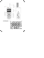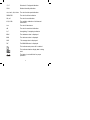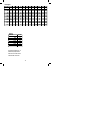
1
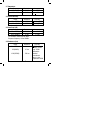
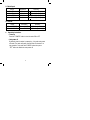
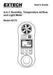
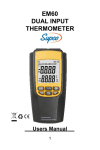
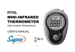
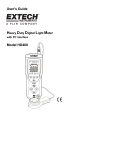
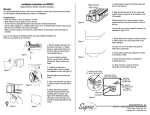
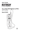
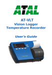
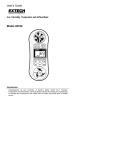
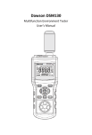
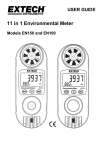
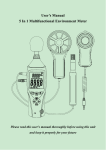
®
EM5
Multifunctional Environmental Meter
User Manual
SEALED UNIT PARTS CO., INC.
Contents
Description
1.
Safety Information
2.
Description
3.
Specifications
4.
Operating Instructions
5.
Accessories
1.
Pages
1
2
6
8
12
Safety information
Read the following safety information carefully before attempting
to operate or service the meter. Use the meter only as specified
in this manual, otherwise, the protection provided by the meter
may be impaired. With proper use and care, your digital meter will
provide service for years.
1.2 During use
• Operate the meter under the stated temperature and
humidity conditions.
• Please do not store or use meter in areas exposed to direct
sunlight, high temperature, humidity or condensation.
• Do not touch or manipulate the sensor.
• Do not expose the sensor to direct light, this may
cause a false reading.
• Do not expose the sensor to static electricity.
• Never place the sensor directly into water.
1
1.3 Symbols
Complies with EMC (Electromagnetic Compatibility Directive),
Important safety information.
1.4 Maintenance
• Repairs or servicing not covered in this manual should
only be performed by qualified personnel.
• If dust is present on the sensor, use clean air to blow it
away or use alcohol to lightly scrub it away.
Do not use other chemicals for cleaning the sensor.
• Do not use abrasives or solvents on the meter, use a damp
cloth and mild detergent only.
• Always set the power switch to the OFF position when the
meter is not in use.
• If the meter is to be stored for a long period of time, the
batteries should be removed to prevent damage to the unit.
2. Description
The EM5 Digital Multifunctional Environmental Meter combines the
function of Sound Level, Luminometer, Relative Humidity Meter,
Temperature Meter and Anemometer.
• Large LCD and back light for easy reading.
• Data hold function.
• Auto ranging feature.
• MAX, MIN, AVG and DIF (MIN-MAX) value.
• Auto/manual power off.
• Low battery indication.
2
2.1 Button and components identification
(1) Microphone.
(2) LCD Display.
(3) “SET” - Sets the Parameters for Air Volume Measurement.
(4) “MODE” - Selects MAX,MIN,AVG and DIF (MAX-MIN).
(5) “LUX” - Selects Light Meter Function.
(6) “dB” - Selects Sound Level Value Measurement.
(7) “BL” - Activates Back Light Feature.
(8) Airflow Sensor.
(9) “UNIT” - Selects the Units of Measurement.
(10) “HOLD” - Data Hold Function.
(11) “ANEMO” - Air Flow and Volume Features.
(12) “POWER” - Power “On” Manual “Off”.
(13) “TEMP/%RH” - Activates Temperature and Relative
Humidity Measurement.
(14) Light Sensor.
(15) Windscreen.
(16) Temperature / Humidity Sensor.
(17) Tripod Connector.
3
2.2 LCD illustration
4
°F, °C
Fahrenheit / Centigrade indication.
%RH
Relative Humidity indication.
m/s, km/h, ft/s, Knots The unit of wind speed indication.
CMM,CFM
The unit of airflow indication.
ft2, m2
The unit of area indication.
X10, X100
The multiplier indication of airflow and
illuminance.
Lux
The unit of illuminance.
dB
The unit of sound level indication.
A,C
A-weighting, C-weighting indication.
MAX
The maximum value is displayed.
MIN
The minimum value is displayed.
AVG
The average value is displayed.
DIF
The MAX-MIN value is displayed.
This indicates auto power off is enabled.
This indicates that the display data is being
held.
The battery is not sufficient for proper
operation.
5
3. Specifications
• Numerical Display: 4 digit Liquid Crystal Display.
• Response Time: 2 times/second.
• Operating Environment: 14°F to 140°F (-10°C to 60°C).
•Storage Environment: 14°F to 122°F (-10°C to 50°C).
• Power Requirements: 9V battery.
• Low Battery Indication:
displayed.
• Dimensions: 11”(L) x 3.5”(W) x 2”(H)
(280(L) x 89(W) x 50(H)mm).
• Weight: Approximately 15.3 oz (430g).
6
3.1 Temperature
Range
14°F to 140°F
-10°C to 60°C
Resolution
0.1°F
0.1°C
Accuracy
+2.7°F
+1.5°C
Resolution
0.1%RH
0.1%RH
Accuracy
+3%RH@77°F
+5%RH@77°F
3.2 Relative Humidity
Range
20 to 80%RH
(<20 >80)%RH
3.3 Sound level (dB)
Range
Resolution
30 to 130dB(A)
0.1dB
35 to 130dB(C)
0.1dB
Test condition: 94dB 1kHz sine wave.
Response frequency: 100 to 8000Hz.
Accuracy
+1.5dB
+1.5dB
3.4 Illuminance (Lux)
Range
0 to 2000Lux
Resolution
1Lux
X10(20000)
10 Lux
X100(50000)
100 Lux
7
Accuracy
+(5.0% of rdg +
10digits) at color
temp. 2850K
calibrated to
standard
incandescent
lamp at color
temperature 2856K
3.5 Wind Speed
Range
0.5 to 20m/s
1.8 to 72km/h
1.6 to 65.7ft/s
0.9 to 38.9knots
Resolution
0.1m/s
0.1km/h
0.1ft/s
0.1knots
Accuracy
+(3% of rdg+10digits)
+(3% of rdg+10digits)
+(3% of rdg+10digits)
+(3% of rdg+10digits)
3.6 Airflow
Range
0 to 999900CFM
0 to 999900CMM
4.
Resolution
0.1 to 100 CFM
0.1 to 1000 CMM
Accuracy
+(3% of rdg+10digits)
+(3% of rdg+10digits)
Operating Instructions
• Power-up
Press the “POWER” button to turn the meter ON or OFF.
• Auto power off
By default, when the meter is powered on, it is under auto power
off mode. The meter will power itself off after 20 minutes if no
key operation. Press and hold "POWER" button then press
“SET” button to disable the auto power off.
8
• Read hold
Hold the present reading and keep it on the display by
pressing the “HOLD” button. When the held data is no longer
needed, release the data-hold operation by pressing “HOLD”
button again.
• Back light
Press “BL” button to turn on the back light which will last for
10 sec. To turn off at any time press the “BL” button again.
NOTE:
• LED is the main source of back light. Its working current
is large. Frequent use of back light will shorten the battery
life.
• When the battery voltage is less than 7V, it will show
If back light is used at the same time,
may
come up. When
shows, the accuracy of the
measurement can not be assured. Replace the battery
when
appears and back light is not in use.
• AVG/MAX/MIN/DIF measurement
Press the “MODE” button, to select
AVG/MAX/MIN/DIF(MAX-MIN) value to measure.
9
.
4.6
Temperature measurement
For measurement, place the sensor probe in the
environment to be tested. Press the “TEMP/%RH” button to
measure. When the meter is first powered on, the default
scale setting is set at Celsius °C scale. The user may change
it to Fahrenheit °F by pressing “UNIT” button and vice versa
to Celsius by pressing “UNIT” button again.
4.7
Humidity measurement
For measurement, place the sensor probe in the tested
environment. Press the “TEMP/%RH” two times. The
meter will enter Humidity measurement mode. The response
time of the sensor is 5 seconds.
4.8
Sound level (dB) measurement
Aim the sensor on top of the meter to the sound source.
Press the “dB” button to measure. The LCD display will
show the sound level at the meter. When the meter is first
powered on, the default scale setting is set at A-Weighting
scale. The user may change it to C-Weighting by pressing
“UNIT” button and A-Weighting by pressing “UNIT” button
again.
NOTE:
Strong wind striking the microphone may cause inaccurate
measurement in windy locations. A windscreen should be
used in front of microphone.
10
4.9
Luminance(Lux) measurement
Move the sensor on top of the meter to light source in a
horizontal position. Press the “Lux” button to measure. The
LCD display will show the luminance at the meter.
4.10
Wind speed measurement
For measurement, place the sensor of anemometer in the
environment to be tested, be sure the fan is in a upright
position to the air current, and press the “ANEMO” button to
measure. When the meter is first powered on, the default
scale setting is set at m/s scale. The user may change it to
km/h, ft/m and knots by pressing “UNIT” button.
4.11
Air flow measurement
Before measurement press “SET” button to enter the area of
the air current. Press “UNIT” button to select which digit of the
area to change. Press “HOLD” button and “BL” button to
change the selection to the value needed. Press “SET” button to
save the setting.
Place the sensor for anemometer in the environment to be
tested, be sure fan is in upright position, face to the air current,
and press “ANEMO” button to measure.
When the meter is powered on the default scale is CMM, area
set default is 1.0m 2 . To change to CFM press “UNIT’ button,
then set area.
NOTE:
While measuring the wind speed and the air flow, avoid
direct sunlight.
11
4.12
Battery replacement
If the sign
appears on the LCD display, it indicates that
the battery should be replaced. Turn the unit off. Remove
the battery cover. Replace the exhausted battery with a new
one and replace the battery cover.
4.13
Use the tripod connector
If needed, the meter can be fixed on the tripod.
5.
Accessories Included
• Battery: 9V 6F22.
• Windbreak.
• Operating Manual.
• Tripod.
• Durable Storage Case.
12
Rectangular
H (in)/W (in)
2.0
4.0
6.0
8.0
10.0
12.0
14.0
16.0
18.0
20.0
22.0
24.0
2.0
0.0
0.0
0.1
0.1
0.1
0.1
0.1
0.1
0.2
0.2
0.2
0.2
4.0
0.0
0.1
0.1
0.1
0.2
0.2
0.3
0.3
0.3
0.3
0.4
0.4
Circular
Diameter
6.0
8.0
10.0
12.0
14.0
16.0
18.0
6.0
0.1
0.1
0.2
0.2
0.3
0.3
0.4
0.4
0.5
0.5
0.6
0.7
8.0
0.1
0.1
0.2
0.3
0.4
0.4
0.5
0.6
0.7
0.7
0.8
0.9
10.0
0.1
0.2
0.3
0.4
0.5
0.5
0.6
0.7
0.8
0.9
1.0
1.1
12.0
0.1
0.2
0.3
0.4
0.5
0.7
0.8
0.9
1.0
1.1
1.2
1.3
sq. ft.
0.1
0.2
0.4
0.5
0.7
0.9
1.1
Free Area Calculation in sq. ft.
Dimensions (H/W) in inches
Note: Free area in this chart is
based on 0.65 of face area
13
14.0
0.1
0.3
0.4
0.5
0.6
0.8
0.9
1.0
1.2
1.3
1.4
1.5
16.0
0.1
0.3
0.4
0.6
0.7
0.9
1.0
1.2
1.3
1.4
1.6
1.7
18.0
0.2
0.3
0.5
0.7
0.8
1.0
1.1
1.3
1.5
1.6
1.8
2.0
20.0
0.2
0.4
0.5
0.7
0.9
1.1
1.3
1.4
1.6
1.8
2.0
2.2
22.0
0.2
0.4
0.6
0.8
1.0
1.9
1.4
1.6
1.8
2.0
2.2
2.4
24.0
0.2
0.4
0.7
0.9
1.0
1.3
1.5
1.7
2.0
2.2
2.4
2.6
SEALED UNIT PARTS CO., INC.
PO Box 21, 2230 Landmark Place
Allenwood, NJ 08720 USA
732-223-6644 • Fax 732-223-1617
www.supco.com • [email protected]