1
!
"
!"!#
!
!
!
"
!
$!
#
%!
!
!!""##!#
!
!
"
#!
!
$%$!
!"
!"
!" AXIOMTEK is a trademark of AXIOMTEK Co., Ltd.
IBM is a registered trademark of International Business
Machines Corporation.
MS-DOS, and Windows 95/98/NT/2000 are trademarks of
Microsoft Corporation.
Award is a trademark of Award Software, Inc.
IBM, PC/AT, PS/2, VGA are trademarks of International
Business Machines Corporation.
Intel and Celeron, Pentium III are trademarks of Intel
Corporation.
ATI is a trademark of ATI Technologies Inc.
Other brand names and trademarks are the properties
and registered brands of their respective owners.
Chapter 1 Introduction
1.1
1.2
1.3
1.4
General Description ................................ 1
Specifications ......................................... 2
Utilities Supported .................................. 3
Board Dimensions................................... 4
Chapter
Chapt er 2 Jumpers and Connectors
2.1
2.2
2.3
Board Layout .......................................... 5
Jumper Settings...................................... 6
2.2.1
2.2.2
2.2.3
2.2.4
2.2.5
2.2.6
2.2.7
Internal Keyboard Connector Power Selection: JP16... 6
VGA Controller Interrupt Control: JP4 ........................... 7
Power Supply Type Selection: JP11 ............................... 7
Watchdog Trigger Mode Setting: JP14.......................... 7
DiskOnChip Memory Segment: JP12 ............................. 7
SCSI Function Interrupt Control: JP7 .............................. 7
COM2 RS232/422/485 Settings: JP1,JP2,JP3 .................. 8
Connectors ............................................. 9
Chapter 3 Installation
3.1
3.2
3.3
System Memory .................................... 11
CPU Installation .................................... 11
Completing Installation.......................... 12
Chapter 4 Hardware Description
4.1
4.2
4.3
4.4
4.5
4.6
4.7
4.8
4.9
4.10
4.11
4.12
Microprocessors ...................................
BIOS .....................................................
I/O Port Address Map ............................
Interrupt Controller................................
General Output Connector.....................
Enhanced IDE Interface Connector ........
VGA Interface .......................................
4.7.1
4.7.2
4.7.3
13
13
14
15
16
17
18
CRT Interface Controller .............................................. 18
Features ........................................................................ 18
VGA Connector: CN18 ................................................ 18
Ethernet Connector ...............................
SCSI Connector ....................................
Floppy Disk Controller ...........................
Parallel Port Interface ............................
Serial Port Interface ..............................
Table of Contents
19
19
19
20
20
4.12.1
Serial Ports IRQ Selection ............................................. 20
Table of Contents
4.13
4.14
4.15
4.16
Keyboard and PS/2 Mouse Connectors ..
USB Connector .....................................
IrDA Connector .....................................
ACPI Connector ....................................
21
21
22
22
Chapter 5 Display Drivers
5.1
5.2
5.3
Introduction .......................................... 23
Features ............................................... 23
Drivers Supported ................................. 24
Chapter 6 Ethernet
6.1
6.2
6.3
Introduction .......................................... 25
Features ............................................... 25
Drivers Supported ................................. 25
Chapter 7 SCSI Controller
7.1
7.2
7.3
Introduction .......................................... 27
Features ............................................... 27
Driver Support ...................................... 28
Chapter 8 Award BIOS Utility
8.1
8.2
8.3
8.4
8.5
8.6
BIOS Introduction ..................................
BIOS Setup ...........................................
Standard CMOS Setup ..........................
BIOS Features Setup .............................
Chipset Features Setup .........................
Power Management Setup ....................
8.6.1
8.6.2
8.6.3
8.7
8.8
8.9
8.10
8.11
8.12
8.13
8.14
29
29
31
34
38
41
PM Timers ...................................................................... 43
PM Events ..................................................................... 43
Reload Global Timer Events ......................................... 45
PNP/PCI Configuration ...........................
Load BIOS Defaults ...............................
Load Setup Defaults..............................
Integrated Peripherals ...........................
Supervisor / User Password ...................
IDE HDD Auto Detection ........................
Save & Exit Setup .................................
Exit Without Saving ...............................
Appendix A
45
47
48
49
52
53
54
55
Watchdog Timer
Using the Watchdog Function ....................... 57
Table of Contents
Appendix B
Connector Pin
Assignments
40-pin IDE Interface Connector: CN6 ...............................................59
Floppy Disk Connector: CN2 ............................................................59
Parallel Port Connector: CN3 ...........................................................60
Serial Ports Pin Assignment ............................................................60
USB Connector: CN10 .....................................................................61
Case Fan Connector: CN23 .............................................................61
CPU Fan Connector: CN24 ..............................................................61
WAKE ON LAN Connector: CN4 .......................................................61
Table of Contents
SBC8163 Socket370 All-in-One CPU Card Series User’s Manual
!
"
"#$
"#$
%%&'()#
(
*'+()#,'-)(
#".
#"+
/01&"#$
Introduction
!
SBC8163 Socket370 All-in-One CPU Card Series User’s Manual
#
"$
#" Chipset:
Intel 440BX AGPset
#" CPU Socket:
#" Bus Clock:
Socket370
66/100 MHz
#" CPU: Intel Socket370 Celeron/Pentium III up to 800MHz
#" L2 Cache:
Integrated in CPU
#" BIOS: Award 2MB PnP Flash BIOS
#" System Memory:
!"3 x 168-pin DIMM sockets
!"Maximum buffered SDRAM 256MB or unbuffered SDRAM
128MB, up to 768MB SDRAM
!"ECC/parity checking
#" IDE Interface:
2 bus mastering EIDE up to four
devices, Ultra DMA/33 supported
#" FDD Interface:
Supports up to 2 drives
#" Serial Ports:
Two 16550 UARTs ports with 16 byte as
one RS-232 and one RS-232/422/485
#" Parallel Ports:
One parallel port with ECP/EPP/SPP
supported
#" VGA Controller:
!"AGP interface controller with onboard 8MB SDRAM
!"VGA chipset ATI Rage XL AGP 2X supporting CRT displays
!"Supports up to 1600x1200 16 bit-color resolution on noninterlaced CRT monitors
#" Ethernet:
!"Intel 82559 PCI Bus 10/100M Base-T
!"Onboard Wake On LAN (via ATX power supply)
!"Onboard RJ-45 connector
,
Introduction
SBC8163 Socket370 All-in-One CPU Card Series User’s Manual
#" Ultra3 Wide SCSI:
!"LSI Symbios SYM53C1010 PCI Bus Ultra3 Wide SCSI interface
!"Two 68-pin 16-bit differential Ultra3 Wide SCSI ports and one
50-pin 8-bit Ultra SCSI port
!"Connects up to 30 SCSI peripherals whit Ultra3 Wide SCSI
feature
!"Provide data transfer rates up to 160MB/sec whit Ultra3 Wide
SCSI, 80MB/sec whit Ultra2 Wide SCSI, 40MB/sec whit Ultra
Wide SCSI, and 20MB/sec with Ultra SCSI interface
#" USB Interface:
2 USB ports; USB Spec. Rev. 1.1
compliant
#" IrDA: 1 IrDA pin-header for wireless communication
#" Hardware Monitoring:
Winbond W83781D controller,
monitoring for CPU/System
temperature, system voltage,
and fan speed
#" Watchdog Timer:
!"Generates a system reset
!"Software programmable time interval and jumper selectable
!"64 levels, 0.5~8/5~80/50~800/100~1600 seconds
#" SSD:
Supports M-Systems DiskOnChip 2000 serials
#" Dimensions:
NOTE:
122(W) x 335(L) mm
Specifications are subject to change without
notice.
""
#"SCSI Utility and Drivers (SCSI functions only)
#"Ethernet Utility and Drivers
#"CRT Drivers
#"System Doctor
Introduction
0
SBC8163 Socket370 All-in-One CPU Card Series User’s Manual
&
%
%
Introduction
SBC8163 Socket370 All-in-One CPU Card Series User’s Manual
&
'(
# Jumpers and Connectors
2
SBC8163 Socket370 All-in-One CPU Card Series User’s Manual
# #
)"
*
34
4
5
Jumper
Jumper Setting
Default Setting
JP1
COM2 Mode Setting: RS232
Short 3-5, 4-6
JP2
COM2 Mode Setting: RS232
Short 1-2, 7-8
JP3
COM2 Mode Setting: RS232
Short 3-5, 4-6
JP4
VGA Interrupt require: Use Interrupt
Open
JP5
Reserved
JP6
Open
Reserved
JP7
Open
SCSI Function: Use Dual Interrupt
JP8
-----
JP9
Reserved
JP10
Reserved
Open
----Open
Short 1-2
Short 1-2, 4-5, 78, 10-11
JP11
Power Supply Type: AT Power Supply
JP12
DiskOnChip Memory Segment DC000-DFFFF
JP13
Reserved
JP14
Watchdog Trigger Mode: Disabled
JP15
Short 7-8
Open
Open
-----
JP16
-----
Int. Keyboard Power Select: System Power
Short 1-2
Power Source
System Power
Suspend Power
Settings
Short 1-2 (default)
Short 2-3
JP16
.
Jumpers and Connectors
SBC8163 Socket370 All-in-One CPU Card Series User’s Manual
Options
Settings
Open (default)
Short
Use Interrupt
Non-Interrupt
!
Options
Settings
AT P/S (default) Short 1-2, 4-5, 7-8, 10-11
Short 2-3, 5-6, 8-9, 11-12
ATX P/S
"
#$!$$%$
"#$
63"#$
Options
Setting
Short 1-2
Short 2-3
Open (default)
NMI
RESET
Disabled
& '()*#%+$+
Options
D0000 D3FFF
D4000 D7FFF
D8000 DBFFF
DC000 DFFFF
Settings
Short
Short
Short
Short
1-2
3-4
5-6
7-8 (default)
,-
Options
Jumpers and Connectors
Use Dual Interrupt
Use One Interrupt
Settings
Open (default)
Short
1
SBC8163 Socket370 All-in-One CPU Card Series User’s Manual
- *%. //0&$(11 COM2
JP1
JP2
JP3
RS-232 (default)
Short 3-5, 4-6
Short 1-3, 2-4
Short 1-3, 2-4
Short 1-2, 7-8
Short 3-4
Short 5-6, 7-8
Short 3-5, 4-6
Short 1-3, 2-4
Short 1-3, 2-4
RS-422
RS-485
7
Jumpers and Connectors
SBC8163 Socket370 All-in-One CPU Card Series User’s Manual
# "#$
/
9
"%
(
:
Connectors
Primary IDE Connector
FDD Connector
Printer Port Connector
COM1 (SBC8163VES And
SBC8163VE Only)
Secondary IDE Connector
50-pin Narrow SCSI
Connector
Label
CN17
CN18
CN20
CN4
Reserved
CN21
CN5
USB Connector
CN22
CN6
PS/2 Keyboard
Connector
PS/2 Mouse Connector
Keyboard/Mouse
Connector
CN23
Fan Power Connector 2
CN26
CN7
-----
CN8
Wide SCSI
Channel 1
Wide SCSI
Channel 2
CN9
CN10
General Output Connector
CN11
Reserved
CN12
Fan Power Connector 1
CN13
IrDA Connector
CN14
Ethernet Connector
(SBC8163VES & VE Only)
CN15
COM1 (SBC8163V Only)
CN16
Jumpers and Connectors
Label
ACPI Connector
VGA Connector
Extrnal Battery
Connector
COM2
68-pin Ultra3(2)
Connector With
68-pin Ultra3(2)
Connector With
Connectors
CN1
CN2
CN3
SCSI Channel 1 LVD
Mode directives LED
Connector
SCSI Channel 2 LVD
Mode directives LED
Connector
Watch-Dog Activity LED
Connector
SCSI Channel 2 Activity
LED Connector
SCSI Channel 1 Activity
LED Connector
Ethernet Boot ROM
Socket
DiskOnChip Socket
CN24
CN25
D2
D4
D6
D7
D9
U16
U22
8
SBC8163 Socket370 All-in-One CPU Card Series User’s Manual
External LAN Card Wake
On LAN Connector
!&
CN19
Jumpers and Connectors
SBC8163 Socket370 All-in-One CPU Card Series User’s Manual
!&
SBC8163 Socket370 All-in-One CPU Card Series User’s Manual
/01&"#$
;
!"Power supply and passive backplane (optional)
!"IBM PC/AT keyboard
!"Display monitor
!"Floppy or hard disk with MS-DOS or Flash Disk emulator
(
(
"#$
!.733
<33
=:
!,73/*(3,2.3/*(3
>!.30,3.%3
!,73
,2.3<=/*(3
NOTE:
#
Use SDRAM modules with PC100 or PC133
specification when running 100MHz CPU bus speed.
With 66MHz CPU bus speed, SDRAM modules with
PC66, PC100 or PC133 specification can be used.
You have to install the Intel Celeron or Pentium III
processor before installing the memory modules.
+
1.
Align pin one (e.g., white dot) of the CPU with pin one
of the socket. Pin one of the CPU socket may either
be marked on the board or indicated by an arrow
head symbol on one corner of the socket. Normally, its
diagonal corner distinguishes pin one on the socket.
2. To complete the CPU installation, gently press the CPU
into place.
3. Double-check the insertion and orientation of the CPU
before applying power. Improper installation will result
in permanent damage to the CPU.
Installation
!!
SBC8163 Socket370 All-in-One CPU Card Series User’s Manual
"*
+
1. Make sure the power is OFF.
2. Set the configuration jumpers according to the jumper
settings on Chapter 2.
3. Install the SBC8163 CPU card into one of the slots on
the passive backplane. You may allow the SBC8163 to
stand alone as a single board computer.
4. Connect the I/O cables and peripherals, i.e. floppy
disk, hard disk, monitor, keyboard, power supply and
etc. to the CPU board.
NOTE:
5.
!,
The color of pin one is usually red or blue,
while others are gray.
Turn ON the system power.
Installation
SBC8163 Socket370 All-in-One CPU Card Series User’s Manual
!
:
/01&"#$
% "
"#"#$
/
"#$
$6'
?/5,+: 65,&&& 82587
3/?/
"#$
"#$
4
"#$"#$""#$-
"
4
3
"#$
"#$
% #
&+
?/
(
#
#
?/,3@9#*?3@
"7
?/
Hardware Description
!0
SBC8163 Socket370 All-in-One CPU Card Series User’s Manual
% +,
"
"#$
5?
!A
5?:
Address
000-01F
020-03F
040-05F
060-06F
070-07F
080-09F
0A0-0BF
0F0
0C0-0DF
0F1
0F8-0FF
120
121
122
1F0-1F8
200-207
300-31F
360-36F
378-37F
3B0-3BF
3C0-3CF
3D0-3DF
3F0-3F7
3F8-3FF
2F8-2FF
!%
Devices
DMA controller #1
Interrupt controller #1
Timer
Keyboard controller
Real time clock, NMI
DMA page register
Interrupt controller #2
Clear math coprocessor busy signal
DMA controller #2
Reset math coprocessor
Math processor
Disable watchdog timer operation (read)
Enable watchdog timer operation (read)
Watchdog
Fixed disk controller
Game port
Prototype card
Reserved
Parallel port #1
MDA video card (including LPT1)
EGA card
CGA card
Floppy disk controller
Serial port #1 (COM1)
Serial port #2 (COM2)
Hardware Description
SBC8163 Socket370 All-in-One CPU Card Series User’s Manual
% %
+"
#"
!./(;
%!.
/(#"!.
;B
NMI
Parity check error
IRQ0
System timer output
Keyboard
Interrupt rerouting from IRQ8 through IRQ15
Serial port #2
Serial port #1
Reserved
Floppy disk controller
Parallel port #1
Real time clock
Reserved (SCSI)
USB
Reserved (VGA/LAN/SCSI)
PS/2 Mouse
Math coprocessor
Primary IDE channel
Secondary IDE Channel
IRQ1
IRQ2
IRQ3
IRQ4
IRQ5
IRQ6
IRQ7
IRQ8
IRQ9
IRQ10
IRQ11
IRQ12
IRQ13
IRQ14
IRQ15
NOTE:
The table above displays the standard mapping list
of the interrupt controller fpr reference. The
displayed mapping list varies for SBC8163V,
SBC8163VE, and SBC8163VES board.
Hardware Description
!2
SBC8163 Socket370 All-in-One CPU Card Series User’s Manual
% -
!
"
CN11
Power LED
0
+9
C
#+9
?6
Keyboard Lock
<C=
<=
External Speaker and Internal Buzzer Connector
>>
"#$
>> :4
<C=
<=
External SMI Button Switch
D
/3
ATX Power On/Off Button
,
D
('
"#$
5
('4
('
!.
Hardware Description
SBC8163 Socket370 All-in-One CPU Card Series User’s Manual
System Reset Switch
D
?@@
HDD Activity LED
:
+9
+9E
D
E+9
C
Reserved pins
% .
/
+
+$
#"
9
5
.%
%9
*(
:
Hardware Description
!1
SBC8163 Socket370 All-in-One CPU Card Series User’s Manual
% 0!
+$
- .!2
(*'+-)(
73-)(*(3
"*
"*:!.&&:!,&&
!.
- ,
(
#"@3 -)(
#""*
#"?
73-)(/*(3
#"/
"*
!.&&:!,&&!.
#""
3
/
#"/3(*3(#
:
#"
)$
#"E
- 30
"*-)(
!2
"*-)(
"-)(
4;
"*5-)(
!7
Hardware Description
SBC8163 Socket370 All-in-One CPU Card Series User’s Manual
CN18: CRT/VGA Connector Pin Assignment
Pin
1
4
7
10
13
Description
Red
N/A
AGND
GND
Horizontal Sync
% 1
Pin
2
5
8
11
14
Description
Green
GND
AGND
N/A
Vertical Sync
Pin
3
6
9
12
15
Description
Blue
AGND
N/A
DDC DAT
DDC CLK
/
*F%2
9
!&!&&4
<
4=!&
% 2
+
/"/!.&3
7&3%&3
,&3/"/
#"CN10: Ultra3 Wide SCSI Connector, 68-pin supports up to
160Mbps SCSI devices
#"CN9:
Ultra3 Wide SCSI Connector, 68-pin supports up to
160Mbps SCSI devices
#"CN6:
Narrow SCSI Connector, 50-pin supports 20Mbps
SCSI devices
% ""(
0%
2,2G0.&A5!,3
02G
1,&A5!%%35,773
(
:
Hardware Description
!8
SBC8163 Socket370 All-in-One CPU Card Series User’s Manual
% +$
#" Standard mode:
IBM PC/XT, PC/AT and PS/2 TM
compatible with bi-directional
parallel port
#" Enhanced mode:
Enhance parallel port (EPP)
compatible with EPP 1.7 and EPP
1.9 (IEEE 1284 compliant)
#" High speed mode:
Microsoft and Hewlett Packard
extended capabilities port (ECP)
IEEE 1284 compliant
+#!<0"E=
?/"3?/
% #
+$
"?3!
<=*/,0,
"?3,<=
*/
,0,5%,,5%72
(.4
!&"?3,
8
"?3!9"#$
!&"?3!
9"#$
*;"?3!
"?3,
*H%
*H0(
?/*/,0,
"?3!
"?3,*/%72
"?3,(
:
,&
Hardware Description
SBC8163 Socket370 All-in-One CPU Card Series User’s Manual
% 3(4
,#
#/5,
2
6
#/5,
CN23/24
CN25
% %
&
$/<$/=
$/
!&$/
CN22
Hardware Description
,!
SBC8163 Socket370 All-in-One CPU Card Series User’s Manual
% -
+
!&(
CN14
% .
+
(
"
#<("#=
:
:
5
.
("#
CN17
,,
Hardware Description
SBC8163 Socket370 All-in-One CPU Card Series User’s Manual
"
!
#!$
- +
-)(
/
<//=
#<=/6
:@533+"9+
#
.8&&&
,2.A:!.*(3
0,
.8&&&
.%,,.87!
/6+"
!.3,%
:+"
>
;
%7&
- #
#"AGP interface controller with onboard 8MB SDRAM
#"VGA chipset ATI Rage XL AGP 2X supporting CRT
displays
#"Display memory supports up to 1600x1200 16 bit-color
resolution on non-interlaced CRT monitors
Display Drivers
,0
SBC8163 Socket370 All-in-One CPU Card Series User’s Manual
- 5
""
*'+-)(
?/
-)(?/
<
3 =(I
"
5
3
JDisplay Driver Folders
#
"*?3
@
NOTE:
,%
Before you begin the driver software installation,
please see the detail of installation procedure from
the driver utility in the Product Information CD-ROM.
Display Drivers
SBC8163 Socket370 All-in-One CPU Card Series User’s Manual
%
. +
;
#
#9999
7&,0
*F%2
. #
#"10Mb/s and 100Mb/s operations
#"Supports 10Mb/s and 100Mb/s N-Way auto negotiation
#"Full duplex capability
#"Full compliance with PCI Revision 2.1
#"PCI Bus Master data transfers
. 5
""
9
:4
66 ,:
0:%:3+(63 0! 6 82
3+(6//"?$6'?6/
#
NOTE: Ethernet
Before you begin the driver software installation,
please see the detailed installation procedure from
the Product Information CD-ROM and be sure to
make installation and backup copies of the driver
files. ,2
SBC8163 Socket370 All-in-One CPU Card Series User’s Manual
,.
SBC8163 Socket370 All-in-One CPU Card Series User’s Manual
&
+
+/
"$,/"/
/"/0;?/
+/
/"/
!.+-
<+-=
/9
</9=/"/
@/"/
$
/"/
$,/"/
$!.&
#"/"/3/</3/=
?/
"#$
?/
#
#" Two separate SCSI channels
#" 16-bit SE/LVD
#" Automatically enabled termination
#" One 68-pin high-density for channel A
#" One 68-pin high-density and one 50-pin header for
channel B
#" Fast, Ultra, and Ultra2 data transfer capability
#" SCSI Plug and Play
#" SCAM (SCSI Configured AutoMatically)
#" Serial NVRAM (Non Volatile Random Access Module) on
each channel for user configuration utility and SCAM
information storage
#" 4 LED connectors for display of SCSI channel state
SCSI Controller
,1
SBC8163 Socket370 All-in-One CPU Card Series User’s Manual
5
""
+/+
/#"/"/
3/?/.&5 0! 82587
602:5%& ,&&&/"?$6'?/
*2$: ,!:
1/1+:6 0!,5%!!52
NOTE: ,7
Before you begin the driver software installation,
please see the detail of installation procedure from
the driver utility in the Product Information CD-ROM
and be sure to make installation and backup copies
of the SCSI Driver Diskettes. Refer to the SCSI User’s
Manual provided in the Product Information CDROM for more information. SCSI Controller
SBC8163 Socket370 All-in-One CPU Card Series User’s Manual
' ()#
"7
(
?/"#$
(
?/
1 &+
+
(
?/<5?/=
*?3"
3(5??/
1 #
&+
"
(
?/
/
?/
*?3/ ?6
(
?/
#KL
/KL
#?/<#?/=
/
/*
K"LK(L
KL
J?@@
?6
Press <DEL> to Enter Setup
K9LK#$L
K#L
K@!L
K9L;
Award BIOS Utility
,8
SBC8163 Socket370 All-in-One CPU Card Series User’s Manual
/33
33
:
STANDARD CMOS SETUP
INTEGRATED PERIPHERALS
BIOS FEATURES SETUP
SUPERVISOR PASSWORD
CHIPSET FEATURES SETUP
USER PASSWORD
POWER MANAGEMENT SETUP
IDE HDD AUTO DETECTION
PNP/PCI CONFIGURATION
SAVE & EXIT SETUP
LOAD BIOS DEFAULTS
EXIT WITHOUT SAVING
LOAD SETUP DEFAULTS
Esc : Quit
$ % & ' : Select Item
F10 : Save & Exit Setup
(Shift) F2 : Change Color
33
(
334
NOTE:
If you find that your computer cannot boot after
making and saving system changes with Setup, the
Award BIOS, via its built-in override feature, resets
your system to the CMOS default settings.
(
:
0&
Award BIOS Utility
SBC8163 Socket370 All-in-One CPU Card Series User’s Manual
1 "
/
"3?//
J
/
"3?/
"3?/
Date (mm:dd:yy) : Sat, Jul 1 2000
Time (hh:mm:ss) :
00 : 00 : 00
TYPE SIZE
Primary Master
Primary Slave
Secondary Master
Secondary Slave:
:
:
:
:
Drive A :
1.44M,3.5 in
Drive B :
None
: EGA / VGA
Video
:
Halt On :
0
0
0
0
0
0
0
0
CYLS
0
0
0
0
HEAD PRECOMP LANDZ SECTOR
0
0
0
0
0
0
0
0
0
0
0
0
0
0
0
0
MODE
CHS
CHS
CHS
CHS
Base Memory
Extended Memory
Other Memory
:
:
:
640K 15360K 384K Total Memory
:
16384K : All Errors
ESC : Quit
$ % & ' : Select Item
PU / PD / + / - : Modify
F1 : Help
(Shift) F2 : Change Color
(
K@!L
4
Award BIOS Utility
0!
SBC8163 Socket370 All-in-One CPU Card Series User’s Manual
#" Date
Day
the day of week, from Sun to Sat, determined by the BIOS, is read only
Mont
h
the month, Jan (1) through Dec (12)
Date
the date, from 1 to 31 (or the maximum allowed in the month), can key
in the numerical / function key
Year
the year, from 1994 to 2079
&'
#" Time
Hour
Minute
Second
From 00 to 23
From 00 to 59
From 00 to 59
&' !
!
#" Primary/Secondary Master/Slave Hard Drives
"
#$$%
&
'
$%
$%
&%
(
&)
'&'&'
&
&'
*+
*
"
%$%,$-'.*+
&
'
"/
)
'&'
)
'&
&0'
1%)-%"
$%
-)
&
-'
! !"
"
%
!
$
&
&$
"
0,
Award BIOS Utility
SBC8163 Socket370 All-in-One CPU Card Series User’s Manual
HEAD
number of cylinders
number of read/write heads
PRECOMP
write precompensation
LANDZ
landing zone
SECTOR
number of sectors
SIZE
Automatically adjust according to the
configuration
Auto
Normal (HD < 528MB)
Large
(for MS-DOS only)
LBA
(HD > 528MB and supports
Logical Block Addressing)
CYLS
MODE
(for IDE HDD only):
NOTE:
The specifications of your drive must match with
the drive table. The hard disk will not work
properly if you enter incorrect information in
these fields. If your hard disk drive type is not
matched or listed, you can use Type User to
define your own drive type manually.
#" Drive A / Drive B
&0
&,
"
&"
5.25 inch PC-type standard drive; 360Kb capacity
5.25 inch AT-type high-density drive; 1.2MB capacity
3.5 inch double-sided drive; 720Kb capacity
3.5 inch double-sided drive; 1.44MB capacity
3.5 inch double-sided drive; 2.88MB capacity
360K, 5.25 in
1.2M, 5.25 in
720K, 3.5 in
1.44M, 3.5 in
2.88M, 3.5 in
#" Video
&
1&
EGA/VG
A
CGA 40
CGA 80
MONO
Enhanced Graphics Adapter/Video Graphics Array. For EGA,
VGA, SEGA, SVGA or PGA monitor adapters. (default)
Color Graphics Adapter, power up in 40 column mode
Color Graphics Adapter, power up in 80 column mode
For Hercules or MDS adapters, includes high resolution
monochrome adapters
Award BIOS Utility
00
SBC8163 Socket370 All-in-One CPU Card Series User’s Manual
#" Halt On
No errors
All errors
All, But Keyboard
All, But Diskette
All, But Disk/Key
1 %
The system boot will halt on any error detected.
(default)
Whenever the BIOS detects a non-fatal error, the
system will stop and you will be prompted.
The system boot will not stop for a keyboard error;
it will stop for all other errors.
The system boot will not stop for a disk error; it will
stop for all other errors.
The system boot will not stop for a keyboard or disk
error; it will stop for all other errors.
&+
"
Virus Warning
CPU Internal Cache
External Cache
CPU L2 Cache ECC Checking
Processor Number Feature
Quick Power On Self Test
Boot Sequence
Swap Floppy Drive
Boot Up Floppy Seek
Boot Up NumLock Status
Gate A20 Option
Typematic Rate Setting
Typematic Rate (Chars/Sec)
Typematic Delay (Msec)
Security Option
PS/2 mouse function control
PCI /VGA Palette Snoop
OS Select For DRAM>64MB
Report No FDD For WIN 95
0%
: Disabled
: Enabled
: Enabled
: Enabled
: Enabled
: Enabled
: C,A,SCSI
: Disabled
: Disabled
: On
: Fast
: Disabled
:6
: 250
: Setup
: Enabled
: Disabled
: Non-OS2
: Yes
Video BIOS Shadow
C8000-CBFFF Shadow
CC000-CFFFF Shadow
D0000-D3FFF Shadow
D4000-D7FFF Shadow
D8000-DBFFF Shadow
DC000-DFFF Shadow
ESC
F1
F5
F6
F7
:
:
:
:
:
:
:
Enabled
Disabled
Disabled
Disabled
Disabled
Disabled
Disabled
: Quit
$ % & ' : Select Item
: Help
PU/PD/+/- : Modify
: Old Values
(Shift) F2 : Color
: Load BIOS Defaults
: Load Setup Defaults
Award BIOS Utility
SBC8163 Socket370 All-in-One CPU Card Series User’s Manual
#" Virus Warning
"
"
$
,$-'
$
&
&
"
NOTE:
Many disk diagnostic programs, which attempt to
access the boot sector table, can cause the virus
warning. If you will run such a program, disable the
Virus Warning feature.
#" CPU Internal Cache / External Cache
#
&20)3
4#
*56
"
#&37
4
8 #
9
9
20)
&
"
#"3
4
",
#" CPU L2 Cache ECC Checking
8 "%###(:;
,
#" Quick Power On Self Test
8 "
-'
3-'4
-<$Enabled
,$-'
#" Boot Sequence
&
&"
!"A, C, SCSI
!"C, CDROM, A
!"D, A, SCSI
!"C only
!"SCSI, A, C
!"C, A, SCSI
!"CDROM, C, A
!"SCSI, C, A
!"LS/ZIP, C
!"
&
Award BIOS Utility
02
SBC8163 Socket370 All-in-One CPU Card Series User’s Manual
#" Swap Floppy Drive
"'/
&
8 ",$-'
&
&0"
&,
&,
"
&0,
#" Boot Up Floppy Seek
8 ",$-'
"
3*=
5=4
&>6=?*=
@6=?
.;).**)&5=
,
#" Boot Up NumLock Status
&<:
,"-<
#" Gate A20 Option
A0;=
A0;=&
"&.),
#" Typematic Rate Setting
8 "
"
8 "
7,
#" Typematic Rate (Chars/Sec)
8 "
1
6
>=
,
#" Typematic Delay (Msec)
8 "
&"
,.
#" Security Option
''
&8 System, &
"'Setup
"
'
&
'
#" PS/2 mouse function control
"
';
&"
Enabled Disabled
0.
Award BIOS Utility
SBC8163 Socket370 All-in-One CPU Card Series User’s Manual
#" PCI/VGA Palette Snoop
'
BA0
)%A$'0B%'0
BA0#
#$BA0
8 "
#$BA0
)%A$'0B%'0BA0
8 "#$BA0
)%A$'0B%'0#
#" OS Select for DRAM > 64MB
6*),20)
-';
,$-'
!"
#" Report No FDD For WIN 95
8 C+
$2D63
&4
&
7
#" Video BIOS Shadow
B,$-'
2-)20)B'
&
#" C8000 - CBFFF Shadow/DC000 - DFFFF Shadow
'2-)
&"
"6*=?,
.=;*?,
2-)
20)
Award BIOS Utility
01
SBC8163 Socket370 All-in-One CPU Card Series User’s Manual
1 -
/"
"
/
SDRAM RAS-to-CAS Delay
SDRAM RAS Precharge Time
SDRAM CAS latency Time
SDRAM Precharge Control
DRAM Data Integrity Mode
System BIOS Cacheable
Video BIOS Cacheable
Video RAM Cacheable
8 Bit I/O Recovery Time
16 Bit I/O Recovery Time
Memory Hole At 15M-16M
Passive Release
Delayed Transaction
!"#
:3
:3
:3
: Disabled
: Non-ECC
: Disabled
: Disabled
: Disabled
:1
:1
: Disabled
: Enabled
: Disabled
$
%
Auto Detect DIMM/PCI Clk
Spread Spectrum
CPU Host Clock
CPU Warning Temperature
Current System Temp.
Current CPU Temperature
Current CPU FAN1 Speed
Current CPU FAN2 Speed
Vcore(V): 1.63V
VTT(V)
3.3V: 3.37V
+5V
+12V: 12.34V
-12V
-5V: -5.16V
:
:
:
:
:
:
:
:
:
:
:
Enabled
Disabled
Default
Disabled
49 o C/120 o F
49 o C/120 o F
0RPM
0RPM
1.50V
5.05V
-11.78V
ESC : Quit
$ % & ' : Select Item
F1 : Help
PU/PD/+/- : Modify
F5 : Old Values
(Shift)F2 : Color
F6 : Load BIOS Defaults
F7 : Load Setup Defaults
#" SDRAM RAS-to-CAS Delay
20)
"
20
'
"320'4#0
'
"3#0'4#
#" SDRAM RAS Precharge Time
"
20'
"
20)
$
"20)
#
#" SDRAM CAS Latency Time
8 20)"
#0'20)
&"
#
07
Award BIOS Utility
SBC8163 Socket370 All-in-One CPU Card Series User’s Manual
#" DRAM Data Integrity Mode
20)
#" System BIOS Cacheable
8 ",$-'2-)
/====E/////E
&
"
#" Video BIOS Cacheable
8 "&,$-'
#====E
#@///E
&
"
#" Video RAM Cacheable
'Enabled&,$-'2-)
#====#@///
"
&
E&
#" 8 Bit I/O Recovery Time
34
"&5"$-
.;
>*+6@
5#
#" 16 Bit I/O Recovery Time
34
"&.6"$-
.;
>*+6@
5
#" Memory Hole at 15MB - 16MB
$
&
"
&
$'0
&.+),
.6),
$'07
.+),&"
%7
.6),,
#" Passive Release
8 "##$"
&
-
"
#$
20)
#" Delayed Transaction
">;"
"
'Enabled
#$&
;.
Award BIOS Utility
08
SBC8163 Socket370 All-in-One CPU Card Series User’s Manual
#" AGP Aperture Size (MB)
F
#$
E
0A
&"
*)5).6)>;)6*).;5);+6)
$%
#" CPU Warning Temperature
(
0"
#
&#
&
#" Current System/CPU Temp.
"
"
#" Current CPU Fan1/Fan2 Speed
2)3
&
4
#
"
$#
#" Vcore(V)/VTT(V)/3.3V/+12V/-12V/+5V/-5V
&
&
"
$#
%&
Award BIOS Utility
SBC8163 Socket370 All-in-One CPU Card Series User’s Manual
1 .
6
*
"
#3/
?@@
ACPI function
Power Management
PM Control by APM
Video Off Method
Video Off After
MODEM Use IRQ
Doze Mode
Standby Mode
Suspend Mode
HDD Power Down
Throttle Duty Cycle
PCI/VGA Act-Monitor
Soft-Off by PWR-BTTN
PowerOn by Ring
Resume by Alarm
:
:
:
:
:
:
:
:
:
:
:
:
:
:
:
Disabled
User Define
Yes
V/H SYNC +Blank
Standby
3
Disable
Disable
Disable
Disable
62.5%
Disabled
Instant-Off
Enabled
Disabled
Onboard LAN Wakeup
: Enabled
PCI LAN Card Wakeup
IRQ 8 Break Suspend
: Enabled
: Disabled
** Reload Global Timer **
IRQ[3-7,9-15],NMI
: Disabled
Primary IDE 0
: Disabled
Primary IDE 1
: Disabled
Secondary IDE 0
: Disabled
Secondary IDE 1
: Disabled
Floppy Disk
: Disabled
Serial Port
: Enabled
Parallel Port
: Disabled
ESC : Quit
$ % & ' : Select Item
F1 : Help
PU/PD/+/- : Modify
F5 : Old Values
(Shift)F2 : Color
F6 : Load BIOS Defaults
F7 : Load Setup Defaults
#" ACPI Function
""0&
#
)30#$4
&"
%""
#" Power Management
3
4
&
!"HDD Power Down
!"Doze Mode
!"Suspend Mode
)
&7
Award BIOS Utility
%!
SBC8163 Socket370 All-in-One CPU Card Series User’s Manual
Disable (default)
No power management. Disables all four modes
Min. Power Saving
Minimum power management. Doze Mode = 1 hr. Standby
Mode = 1 hr., Suspend Mode = 1 hr., and HDD Power Down
= 15 min.
Max. Power Saving
Allows you to set each mode individually. When not disabled,
each of the ranges are from 1 min. to 1 hr. except for HDD
Power Down which ranges from 1 min. to 15 min. and
disable.
User Define
NOTE:
Maximum power management -- . Doze Mode = 1 min., Standby Mode = 1
min., Suspend Mode = 1 min., and HDD Power Down = 1
min.
In order to enable the CPU overheat protection
feature, the Power Management field should not
be set to Disabled.
#" PM Control by APM
8 "0&
)&"
&)7
'&
#
$0&
)30)4
1&"
&$)7
'&""
No
#" Video Off Method
"
V/H SYNC +
Blank
This causes the system to turn off the vertical and horizontal
synchronization ports and write blanks to the video buffer.
DPMS
Select this option if your monitor supports the Display Power
Management Signaling (DPMS) standard of the Video Electronics
Standards to select video power management values.
Blank Screen
This option only writes blanks to the video buffer.
#" Video Off After
8 "
BA0
&
%,
Always On
Monitor will remain on during power saving modes.
Suspend --> Off
Monitor blanked when the system enters the Suspend
mode.
Susp,Stby --> Off
Monitor blanked when the system enters either
Suspend or Standby modes.
All Modes --> Off
Monitor blanked when the system enters any power
saving mode.
Award BIOS Utility
SBC8163 Socket370 All-in-One CPU Card Series User’s Manual
#" Modem Use IRQ
93$2D4
34
0&$2D
&"
>*+@
C.=..<0,$2D#
0 %!+(
)#"
User Defined #
3
/
#" Doze Mode
8 "
&
#
&
#" Standby Mode
0
&7
7
&&-//
&
#" Suspend Mode
8 "
&
&7#"-//
#" HDD Power Down
8 "
&
&
&
&
#" Throttle Duty Cycle
8 F#
1
0 %56(
#35?
On
Award BIOS Utility
%0
SBC8163 Socket370 All-in-One CPU Card Series User’s Manual
#" PCI/VGA Act-Monitor
8 Enabled&&
"
'"&Disabled
#" Soft-Off by PWR-BTTN
0G
$
-//9
Instant-Off
(default)
This option follows the conventional manner systems perform when
power is turned OFF. Instant-Off is a soft power OFF sequence
requiring only the switching of the power supply button to OFF.
Upon turning OFF system from the power switch, this option will
delay the complete system power OFF sequence by approximately 4
Delay 4 Sec. seconds. Within this delay period, system will temporarily enter into
Suspend Mode enabling you to restart the system at once.
#" PowerOn by Ring
0
2$
32$43
4
#" Resume by Alarm
8 Enabled,
2#
3
4
'
#" PCI LAN Card/Onboard LAN Wakeup
8 -:0<
""
&
"
"
"
-"
:0<
7
:0<
3#$:0<#
8 4
#" IRQ 8 Break Suspend
1
$2D532#4
'
&Disabled
%%
Award BIOS Utility
SBC8163 Socket370 All-in-One CPU Card Series User’s Manual
0 .
!+56(
Enabled
/
#" IRQ3 -7, 9-15, NMI
Primary IDE 0
Primary IDE 1
Secondary IDE 0
Secondary IDE 1
Floppy Disk
Serial Port
Parallel Port
1 The
The
The
The
The
The
The
The
default
default
default
default
default
default
default
default
value
value
value
value
value
value
value
value
is
is
is
is
is
is
is
is
“Disabled”.
“Disabled”.
“Disabled”.
“Disabled”.
“Disabled”.
“Disabled”.
“Enabled”.
“Disabled”.
7,+
$*
#"(#"
6M
#"
PNP OS Installed
Resources Controlled by
Reset Configuration Data
: No
: Auto
: Disabled
Award BIOS Utility
Assign IRQ For VGA
: Enabled
Assign IRQ For USB
: Enabled
ESC : Quit
$ % & ' : Select Item
F1 : Help
PU/PD/+/- : Modify
F5 : Old Values
(Shift)F2 : Color
F6 : Load BIOS Defaults
F7 : Load Setup Defaults
%2
SBC8163 Socket370 All-in-One CPU Card Series User’s Manual
#" PNP OS Installed
-'
&"
1<
#" Resource controlled by
0
,$-'
""&
E&
""
8 C+
&"
0)
#" Reset Configuration Data
<
&"'%"
%7'#
3%'#47
'
&
"&"
%""
#" Assign IRQ For USB/VGA
%""$2D
',BA0
&"
%""
%.
Award BIOS Utility
SBC8163 Socket370 All-in-One CPU Card Series User’s Manual
1 1
'
&+
$
?/*?3
STANDARD CMOS SETUP
INTEGRATED PERIPHERALS
BIOS FEATURES SETUP
SUPERVISOR PASSWORD
CHIPSET FEATURES SETUP
USER PASSWORD
POWER MANAGEMENT SETUP
IDE HDD AUTO DETECTION
PNP/PCI CONFIGURA
LOAD BIOS DEFAULT
Load BIOS Defaults (Y/N)? N
ETUP
SAVING
LOAD SETUP DEFAULTS
Esc : Quit
$ % & ' : Select Item
F10 : Save & Exit Setup
(Shift) F2 : Change Color
Load BIOS Defaults except Standard CMOS Setup
?/
"3?//*(3J
6
Award BIOS Utility
%1
SBC8163 Socket370 All-in-One CPU Card Series User’s Manual
1 2
'
"
$
STANDARD CMOS SETUP
INTEGRATED PERIPHERALS
BIOS FEATURES SETUP
SUPERVISOR PASSWORD
CHIPSET FEATURES SETUP
USER PASSWORD
POWER MANAGEMENT SETUP
IDE HDD AUTO DETECTION
PNP/PCI CONFIGURA
LOAD BIOS DEFAULT
ETUP
Load SETUP Defaults (Y/N)? N
SAVING
LOAD SETUP DEFAULTS
Esc : Quit
$ % & ' : Select Item
F10 : Save & Exit Setup
(Shift) F2 : Change Color
Load BIOS Defaults except Standard CMOS Setup
/9$#
"3?//*(3J
6
%7
Award BIOS Utility
SBC8163 Socket370 All-in-One CPU Card Series User’s Manual
1 +*
"/
IDE HDD Block Mode
:
IDE Primary Master
PIO
:
IDE Primary Slave
PIO
:
IDE Secondary Master PIO :
IDE Secondary Slave
PIO :
IDE Primary Master
UDMA :
IDE Primary Slave
UDMA :
IDE Secondary Master UDMA :
IDE Secondary Slave UDMA :
On-Chip Primary
PCI IDE :
On-Chip Secondary
PCI IDE :
USB Keyboard Support
:
Init Display First
:
POWER ON Function
KBC input clock
Onboard FDC Controller
Enabled
Auto
Auto
Auto
Auto
Auto
Auto
Auto
Auto
Enabled
Enabled
Disabled
PCI Slot
Onboard Serial Port 1
Onboard Serial Port 2
UART Mode Select
: 3F8/IRQ4
: 2F8/IRQ3
: Normal
IR Transmission delay
Onboard Parallel Port
Parallel Port Mode
ECP Mode Use DMA
EPP Mode Select
:
:
:
:
:
Enabled
378/IRQ7
SPP
3
EPP1.7
: BUTTON ONLY
: 8 MHz
: Enabled
$ % & ' : Select Item
ESC : Quit
F1 : Help
PU/PD/+/- : Modify
F5 : Old Values
(Shift)F2 : Color
F6 : Load BIOS Defaults
F7 : Load Setup Defaults
#" IDE HDD Block Mode
"
&
#" IDE Primary/Secondary Master/Slave PIO
$%$-3
$-4
$-3=*4
$%&"
$%
)=
*
&&
$0
"
&&"
0)=).);)>)*
Award BIOS Utility
%8
SBC8163 Socket370 All-in-One CPU Card Series User’s Manual
#" IDE Primary/Secondary Master/Slave UDMA
)066"
$%
&
&
)0
&
38 C+-'2;
$%"
&
4
$
&
"
)0>>660",$-'
&"
0)=).);
#" On-Chip Primary/Secondary PCI IDE
$%
$%'Enabled&
#" USB Keyboard Support
'Enabled
&
'
,
3',4
&',"
&"
%""
#" Init Display First
&
#$'
0A
&"
#$'0A
#" POWER ON Function
-<
9
&ButtonOnly
BUTTON-ONLY
2&
Follows the conventional way of turning OFF system power
(via power button).
Password
Upon selecting this option, the KB POWER ON Password line
appears. Press <Enter> and you’ll be prompted to enter and
confirm a password of your choice.
After setting the password, succeeding attempts to power ON
the system will result to null. For system to activate, user
must input the password via keyboard then press <Enter>.
Hot KEY
This option is very similar with that of Password. Hot-key
combinations range from Ctrl-F1 to Ctrl-F12. User may define
this combination from the Hot key Power ON option.
Mouse
Left
This allows system to POWER ON by clicking the left mouse
button. To enable, user must reboot and allow system to
finish booting up otherwise the setting will not take effect.
Mouse Right
This allows system to POWER ON by clicking the right mouse
button. To enable this setting, user must reboot and allow
system to finish the boot up process otherwise the setting will
not take effect.
Award BIOS Utility
SBC8163 Socket370 All-in-One CPU Card Series User’s Manual
#" KBC input clock
"
&8 MHz
#" Onboard FDC Controller
'%"
3/#4
"
$
/#
&"
&"
%""
#" Onboard Serial Port 1/Port 2
'
&"
>/5$2D*
;%5$2D>>%5$2D*;/5$2D>"0
#" UART Mode Select
("IrDA
("ASKIR IrDA-compliant serial infrared port
("Normal (default value)
NOTE:
The UART Mode Select will not appear on the
menu once you disable the setting of Onboard
Serial Port 2.
8 02)'0'?$2
$
0
2770&$2
#" IR Transmission delay
/7
E7
$
"&Enabled
#" Onboard Parallel Port
"
$-
&"
>@5E$2D@;@5E$2D+>,#$2D@"
#" Parallel Port Mode
'
"
3
4
'<
9
&"
%.C%#'%#%.@%.@
Award BIOS Utility
2!
SBC8163 Socket370 All-in-One CPU Card Series User’s Manual
#" ECP Mode Use DMA
')0
%#
&"
31
#" EPP Mode Select
'%
.@
.C
1 "5
,
6
/
#
/$#
:
K9L9
#
K9L
(
4K9L
(
?
/
STANDARD CMOS SETUP
INTEGRATED PERIPHERALS
BIOS FEATURES SETUP
SUPERVISOR PASSWORD
CHIPSET FEATURES SETUP
USER PASSWORD
POWER MANAGEMENT SETUP
IDE HDD AUTO DETECTION
PNP/PCI CONFIGURA
ETUP
Enter Password :
LOAD BIOS DEFAULT
SAVING
LOAD SETUP DEFAULTS
Esc : Quit
$ % & ' : Select Item
F10 : Save & Exit Setup
(Shift) F2 : Change Color
2,
Award BIOS Utility
SBC8163 Socket370 All-in-One CPU Card Series User’s Manual
1 #
+
8
9
/
"3?//
&'(
)(
'*
(
(+!
*)
(&+
!+(
,-
!.$
,-
!.
+
/#
$
+&+
&'(
)(
'*
(
(+!
*)
(&+
!+(
'#
0
0
0
0
0
0
0
+!*
$9
;
:
JB:
6
Award BIOS Utility
20
SBC8163 Socket370 All-in-One CPU Card Series User’s Manual
1 5
9
:
"
J;
"3?/6
/
STANDARD CMOS SETUP
INTEGRATED PERIPHERALS
BIOS FEATURES SETUP
SUPERVISOR PASSWORD
CHIPSET FEATURES SETUP
USER PASSWORD
POWER MANAGEMENT SETUP
IDE HDD AUTO DETECTION
PNP/PCI CONFIGURA
LOAD BIOS DEFAULT
SAVE to CMOS and EXIT (Y/N)? N
ETUP
SAVING
LOAD SETUP DEFAULTS
Esc : Quit
$ % & ' : Select Item
F10 : Save & Exit Setup
(Shift) F2 : Change Color
Saves all Data & Exit Setup
2%
Award BIOS Utility
SBC8163 Socket370 All-in-One CPU Card Series User’s Manual
1 %
:
;/
5*
/:/
J;
/
6
/
STANDARD CMOS SETUP
INTEGRATED PERIPHERALS
BIOS FEATURES SETUP
SUPERVISOR PASSWORD
CHIPSET FEATURES SETUP
USER PASSWORD
POWER MANAGEMENT SETUP
IDE HDD AUTO DETECTION
PNP/PCI CONFIGURA
LOAD BIOS DEFAULT
Quit Without Saving (Y/N)? N
ETUP
SAVING
LOAD SETUP DEFAULTS
Esc : Quit
$ % & ' : Select Item
F10 : Save & Exit Setup
(Shift) F2 : Change Color
Abandon all Data & Exit Setup
Award BIOS Utility
22
SBC8163 Socket370 All-in-One CPU Card Series User’s Manual
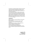
2.
SBC8163 Socket370 All-in-One CPU Card Series User’s Manual
'*'
+
,
*
/
;/*
"#$
,&
<63=
4
@
Start
↓
Un-Lock WDT
:
OUT 120H 0AH ; enter WDT function
OUT 120H 0BH ; enable WDT function
↓
Set multiple (1~4)
:
OUT 120 0NH ; N=1,2,3 or 4
↓
Set base timer (0~F)
:
OUT 121 0MH ; M=0,1,2,…F
↓
re-set timer
:
OUT 121 0MH ; M=0,1,2,…F
↓
IF No re-set timer
:
WDT time-out, generate RESET or NMI
↓
IF to disable WDT
:
OUT 120 00H ; Can be disable at any time
↓
WDT counting
Watchdog Timer
21
SBC8163 Socket370 All-in-One CPU Card Series User’s Manual
M
0
1
2
3
4
5
6
7
8
9
A
B
C
D
E
F
27
N
1
0.5 sec.
1 sec.
1.5 secs.
2 secs.
2.5 secs.
3 secs.
3.5 secs.
4 secs.
4.5 secs.
5 secs.
5.5 secs.
6 secs.
6.5 secs.
7 secs.
7.5 secs.
8 secs.
5
10
15
20
25
30
35
40
45
50
55
60
65
70
75
80
2
secs.
secs.
secs.
secs.
secs.
secs.
secs.
secs.
secs.
secs.
secs.
secs.
secs.
secs.
secs.
secs.
50
100
150
200
250
300
350
400
450
500
550
600
650
700
750
800
3
secs.
secs.
secs.
secs.
secs.
secs.
secs.
secs.
secs.
secs.
secs.
secs.
secs.
secs.
secs.
secs.
100
200
300
400
500
600
700
800
900
1000
1100
1200
1300
1400
1500
1600
4
secs.
secs.
secs.
secs.
secs.
secs.
secs.
secs.
secs.
secs.
secs.
secs.
secs.
secs.
secs.
secs.
Watchdog Timer
SBC8163 Socket370 All-in-One CPU Card Series User’s Manual
'*
-',
40-pin IDE Interface Connector: CN6
Pin
1
4
7
10
13
16
19
22
25
28
31
34
37
40
Description
Reset #
Data 8
Data 5
Data 11
Data 2
Data 14
GND
GND
IOR #
No connector
Interrupt
No connector
HDC CS0 #
GND
Pin
2
5
8
11
14
17
20
23
26
29
32
35
38
Description
Pin
GND
Data 6
Data 10
Data 3
Data 13
Data 0
No connector
IOW #
GND
No connector
No connector
SA0
HDC CSI #
Description
3
6
9
12
15
18
21
24
27
30
33
36
39
Data 7
Data 9
Data 4
Data 12
Data 1
Data 16
No connector
GND
IOCHRDY
GND-Default
SA1
SA2
HDD Active #
Floppy Disk Connector: CN2
Pin
1
4
7
10
13
16
19
22
25
28
31
34
Description
GND
No connector
GND
Motor enable A#
GND
Motor enable B#
GND
Write data#
GND
Write protect#
GND
Disk change#
Pin
2
5
8
11
14
17
20
23
26
29
32
Connector Pin Assignments
Description
Reduce write current
GND
Index#
GND
Drive select A#
GND
STEP#
GND
Track 0 #
GND
Side 1 select#
Pin
3
6
9
12
15
18
21
24
27
30
33
Description
GND
No connector
GND
Drive select B#
GND
Direction#
GND
Write gate#
GND
Read data#
GND
28
SBC8163 Socket370 All-in-One CPU Card Series User’s Manual
Parallel Port Connector: CN3
Pin
1
2
3
4
5
6
7
8
9
10
11
12
13
Description
Strobe#
Data 0
Data 1
Data 2
Data 3
Data 4
Data 5
Data 6
Data 7
Acknowledge#
Busy
Paper Empty#
Printer Select
Pin
14
15
16
17
18
19
20
21
22
23
24
25
26
Description
Auto Form Feed#
Error#
Initialize#
Printer Select In#
GND
GND
GND
GND
GND
GND
GND
GND
Serial Ports Pin Assignment
CN16 Pin CN4/7 Pin
.&
2
Data Set Ready (DSR)
2
3
Receive Data (RXD)
7
4
Request to Send (RTS)
3
5
Transmit Data (TXD)
8
6
Clear to Send (CTS)
4
7
Data Terminal Ready (DTR)
9
8
Ring Indicator (RI)/5V/12V
5
9
Ground (GND)
X
10
1
6
0
Data Carrier Detect (DCD)/5V/12V
1
Description
1
CN4 / CN7
CN16
GND
Connector Pin Assignments
SBC8163 Socket370 All-in-One CPU Card Series User’s Manual
USB Connector: CN10
Pin
1
3
5
7
9
Description
USB Vcc
USB P0USB P0+
GND
No connector
Pin
2
4
6
8
10
Description
USB Vcc
USB P1USB P1+
GND
No connector
Case Fan Connector: CN23
Pin
1
2
3
Description
Speed Sensor
+12V
GND
CPU Fan Connector: CN24
Pin
1
2
3
Description
Speed Sensor
+12V
GND
WAKE ON LAN Connector: CN4
Pin
1
2
3
Connector Pin Assignments
Description
5VSB
GND
WOL
.!
SBC8163 Socket370 All-in-One CPU Card Series User’s Manual
.,