1
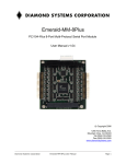
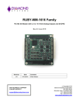
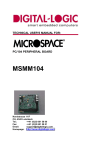
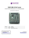
Janus-MM-4LP User Manual
PC/104-Plus Dual or Quad CAN Port Module
Revision
Date
A.00
10/28/2015
Comment
Initial release
Copyright 2015
Diamond Systems Corporation
555 Ellis Street
Mountain View, CA 94043 USA
Tel 1-650-810-2500
Fax 1-650-810-2525
www.diamondsystems.com
FOR TECHNICAL SUPPORT
PLEASE CONTACT:
[email protected]
Janus-MM-4LP User Manual Rev A.00
www.diamondsystems.com
Page 1
CONTENTS
1.
2.
Important Safe Handling Information .............................................................................................................3
Introduction .......................................................................................................................................................4
2.1 Description .....................................................................................................................................................4
2.2 Features .........................................................................................................................................................4
2.3 Operating System Support ............................................................................................................................4
2.4 Mechanical, Electrical, Environmental ...........................................................................................................4
3. Functional Overview .........................................................................................................................................5
3.1 Functional Block Diagram ..............................................................................................................................5
3.2 Mechanical Board Drawing ............................................................................................................................6
3.3 Key Subsystems ............................................................................................................................................7
3.3.1
CAN Controllers ....................................................................................................................................7
3.3.2
CAN Transceivers .................................................................................................................................7
3.3.3
Isolation .................................................................................................................................................7
3.3.4
Digital I/O ..............................................................................................................................................8
3.3.5
Power Supply ........................................................................................................................................8
3.3.6
Multi Host Interface ...............................................................................................................................8
3.3.7
PCI Bus Interface ..................................................................................................................................9
3.3.8
PCI Configuration Space ......................................................................................................................9
3.3.9
ISA host Interface .............................................................................................................................. 10
3.3.10 Programmable Chip Selects .............................................................................................................. 10
4. Board Layout .................................................................................................................................................. 11
4.1 Connector List............................................................................................................................................. 12
5. Connector Pinout and Pin Description ........................................................................................................ 13
5.1 CAN ............................................................................................................................................................ 13
5.2 Digital I/O .................................................................................................................................................... 13
5.3 ISA Connector ............................................................................................................................................ 14
5.4 PC-104 ........................................................................................................................................................ 15
6. Jumper Configuration ................................................................................................................................... 16
6.1 Termination Jumpers .................................................................................................................................. 16
7. Driver installation........................................................................................................................................... 20
7.1 Installing the Software ................................................................................................................................ 20
7.2 Setting the Baud Rate ................................................................................................................................ 21
7.3 Setting the CAN ID and Message Length .................................................................................................. 22
7.4 Writing a Message ...................................................................................................................................... 23
7.5 Viewing Messages ...................................................................................................................................... 24
8. Port Configuartion and Management........................................................................................................... 26
8.1 API to Configure and Manage CAN ports. ................................................................................................. 26
8.1.1
Baud rate configuration. ..................................................................................................................... 27
8.1.2
CAN Receive Prototype. .................................................................................................................... 28
9. DIgital I/O COnfiguration ............................................................................................................................... 30
10. Specifications................................................................................................................................................. 31
Janus-MM-4LP User Manual Rev 0.9
www.diamondsystems.com
Page 2
1. IMPORTANT SAFE HANDLING INFORMATION
WARNING!
ESD-Sensitive Electronic Equipment
Observe ESD-safe handling procedures when working with this product.
Always use this product in a properly grounded work area and wear appropriate
ESD-preventive clothing and/or accessories.
Always store this product in ESD-protective packaging when not in use.
Safe Handling Precautions
This board contains a high density connector with many connections to sensitive electronic components. This
creates many opportunities for accidental damage during handling, installation and connection to other
equipment. The list here describes common causes of failure found on boards returned to Diamond Systems for
repair. This information is provided as a source of advice to help you prevent damaging your Diamond (or any
vendor’s) embedded computer boards.
ESD damage – This type of damage is usually almost impossible to detect, because there is no visual sign of
failure or damage. The symptom is that the board eventually simply stops working, because some component
becomes defective. Usually the failure can be identified and the chip can be replaced. To prevent ESD damage,
always follow proper ESD-prevention practices when handling computer boards.
Damage during handling or storage – On some boards we have noticed physical damage from mishandling. A
common observation is that a screwdriver slipped while installing the board, causing a gouge in the PCB surface
and cutting signal traces or damaging components.
Another common observation is damaged board corners, indicating the board was dropped. This may or may not
cause damage to the circuitry, depending on what is near the corner. Most of our boards are designed with at
least 25 mils clearance between the board edge and any component pad, and ground / power planes are at least
20 mils from the edge to avoid possible shorting from this type of damage. However these design rules are not
sufficient to prevent damage in all situations.
A third cause of failure is when a metal screwdriver tip slips, or a screw drops onto the board while it is powered
on, causing a short between a power pin and a signal pin on a component. This can cause overvoltage / power
supply problems described below. To avoid this type of failure, only perform assembly operations when the
system is powered off.
Sometimes boards are stored in racks with slots that grip the edge of the board. This is a common practice for
board manufacturers. However our boards are generally very dense, and if the board has components very close
to the board edge, they can be damaged or even knocked off the board when the board tilts back in the rack.
Diamond recommends that all our boards be stored only in individual ESD-safe packaging. If multiple boards are
stored together, they should be contained in bins with dividers between boards. Do not pile boards on top of each
other or cram too many boards into a small location. This can cause damage to connector pins or fragile
components.
Power supply wired backwards – Our power supplies and boards are not designed to withstand a reverse
power supply connection. This will destroy each IC that is connected to the power supply (i.e. almost all ICs). In
this case the board will most likely will be unrepairable and must be replaced. A chip destroyed by reverse power
or by excessive power will often have a visible hole on the top or show some deformation on the top surface due
to vaporization inside the package. Check twice before applying power!
Overvoltage on digital I/O line – If a digital I/O signal is connected to a voltage above the maximum specified
voltage, the digital circuitry can be damaged. On most of our boards the acceptable range of voltages connected
to digital I/O signals is 0-5V, and they can withstand about 0.5V beyond that (-0.5 to 5.5V) before being damaged.
However logic signals at 12V and even 24V are common, and if one of these is connected to a 5V logic chip, the
chip will be damaged, and the damage could even extend past that chip to others in the circuit
Janus-MM-4LP User Manual Rev 0.9
www.diamondsystems.com
Page 3
2. INTRODUCTION
2.1
Description
The Janus-MM-4LP-XT family of I/O modules offers two or four opto-isolated CANbus 2.0B ports plus 16 digital
I/O lines. Models are available in both the PC/104-Plus and PC/104 form factors. Janus-MM-4LP is based on
Xilinx Artix-7 FPGA. This core houses the CAN controller logic and digital I/O logic providing data rates up to
1Mbps. Each CAN port supports standard and extended frames as well as expanded TX and RX message
queues for enhanced performance. Each port has its own combination isolator and transceiver chip. The 16
digital I/O lines have a selectable voltage level of +3.3V or +5V.
2.2
Features
2 or 4 CAN 2.0B compatible ports
Data rates up to 1Mbps
Supports standard 11-bit identifier and extended 29-bit identifier frames
Extended TX and RX message queues for enhanced performance
16 8-byte transmit message queues
31 8-byte receive message queues
16 receive filters
Galvanically isolated transceivers
500V port-to-host and port-to-port isolation
Jumper selectable biased split termination for improved noise reduction
16 digital I/O lines
Latching I/O connectors for increased ruggedness
PCI and ISA bus interfaces
2.3
Operating System Support
Windows Embedded 7 and Linux Ubuntu 12.04LTS
Basic CAN driver included with APIs and monitor program
2.4
Mechanical, Electrical, Environmental
PC/104-Plus form factor compliant, 3.55” x 3.775” (90mm x 96mm) without wings
-40°C to +85°C ambient operating temperature
Power input requirements: +5VDC +/- 5%
PCI (3.3V) and ISA (5V) host interfaces
MIL-STD-202G shock and vibration compatible
Janus-MM-4LP User Manual Rev 0.9
www.diamondsystems.com
Page 4
3. FUNCTIONAL OVERVIEW
3.1
Functional Block Diagram
Figure 1 shows the block diagram for Janus-MM-4LP.
Figure 1: Block Diagram
Janus-MM-4LP User Manual Rev A.00
www.diamondsystems.com
Page 5
3.2
Mechanical Board Drawing
Figure 2 shows the mechanical drawing for Janus-MM-4LP. The module adheres to the PC/104-Plus standard.
Figure 2: Mechanical Drawing
Janus-MM-4LP User Manual Rev 0.9
www.diamondsystems.com
Page 6
3.3
Key Subsystems
3.3.1
CAN Controllers
The module has two or four CANbus 2.0 controllers implemented as FPGA cores inside a Xilinx Artix-7 FPGA.
The FPGA core provides the following key features:
Conforms to the ISO 11898 -1, CAN 2.0A, and CAN 2.0B standards
Supports both standard (11-bit identifier) and extended (29-bit identifier) frames
Supports bit rates up to 1Mbps
Transmit message FIFO with a user-configurable depth of up to 64 messages
Transmit prioritization through one High-Priority Transmit buffer
Automatic re-transmission on errors or arbitration loss
Receive message FIFO with a user-configurable depth of up to 64 messages
Acceptance filtering with a user-configurable number of up to 16 acceptance filters
Sleep Mode with automatic wake-up
Loop Back Mode for diagnostic applications
Maskable Error and Status Interrupts
Readable Error Counters
3.3.2
CAN Transceivers
The CAN transceivers are Analog Devices ADM3053 with a combination of isolation and transceiver. The device
is powered by +5V. It generates isolated power to power the isolated side of the transceiver and the transceivers
feature programmable slope control with a resistor.
3.3.3
Isolation
Janus-MM-4LP supports 500V isolation between each CAN port and the host, and between each CAN port and
the other via the ADM3053 isolated transceiver. An insulating film has been added to the bottom of the PCB in
the isolated area for additional protection.
Janus-MM-4LP User Manual Rev 0.9
www.diamondsystems.com
Page 7
3.3.4
Digital I/O
Janus-MM-4LP offers 16 digital I/O lines organized in two 8-bit I/O ports which are buffered with external data
transceivers. The logic levels are jumper-selectable for 3.3V or 5V operation, and the DIO lines have jumperselectable pull-up / pull-down resistors. The entire circuit is enabled or disabled based on the settings of 3 I/O
configuration jumpers. When the circuit is enabled, the 8-bit ports are accessed at registers Base + 0 (Port A) and
Base + 1 (Port B), where Base is the base address selected with jumpers JA9-5.
The ports power-up and reset to 0 and input mode. When a port is in output mode, its I/O pins are in output mode
and reflect the value of the corresponding output registers, and these output values may also be read back during
a read cycle to the port’s address. When a port is in input mode, its I/O pins are in input mode, and their values
are read back during a read cycle to the port’s address.
Each port’s direction is controlled by a bit in a control register at Base + 3. When a control bit is 0, the port is in
input mode, and when it is 1, the port is in output mode. The control register powers up and resets to 0. The
control register may also be read back during a read cycle to Base + 3.
The FPGA has an output pin P_LED which can be used to drive an LED to indicate the FPGA is alive and
responding to commands. P_LED is controlled by the LED bit in the register at base + 2. The pin logic level is the
opposite of the register value. On power-up or reset the register bit is 1 and the pin is low, turning the LED on. A 0
turns the LED off.
Offset
7
6
5
4
3
2
1
0
0 (R/W)
DIOA7
DIOA6
DIOA5
DIOA4
DIOA3
DIOA2
DIOA1
DIOA0
1 (R/W)
DIOB7
DIOB6
DIOB5
DIOB4
DIOB3
DIOB2
DIOB1
DIOB0
2 (W)
LED
2 (R)
3 (R/W)
3.3.5
DIRB
DIRA
Power Supply
The module is powered by +5V from the PCI and ISA connectors. It provides all other required voltages on board,
including +3.3V for the CAN transceivers and the FPGA core voltages.
The digital I/O connector provides power for external circuitry. The voltage is selected between 3.3V and 5V with
a jumper which also controls the voltage of the digital I/O transceivers. The current is limited via a poly-switch
thermal resettable fuse with a hold current capacity of 350mA.
3.3.6
Multi Host Interface
The FPGA used on the board contains a PCI interface core and ISA interface core. Both the PCI and ISA
interfaces are available. Only one bus interface can be active at any time. The active interface is selected with a
bus power (+5V) signal from the PCI connector routed through a jumper to an input pin on the FPGA. If the FPGA
detects a high on the input pin, the PCI interface is used; otherwise the ISA interface is used.
If the PCI interface is not selected, it is inactive, and all FPGA PCI interface pins are tristated. Likewise, if the ISA
interface is not selected, it is inactive, and all FPGA ISA bus interface pins are tristated.
Janus-MM-4LP User Manual Rev 0.9
www.diamondsystems.com
Page 8
3.3.7
PCI Bus Interface
The FPGA includes a 32-bit 33MHz PCI core that interfaces to the PC/104-Plus PCI. The PCI host interface may
be selected by a combination of power pin detection and jumper enable. The PCI interface includes 5 memory
address ranges: four for the CAN controllers and one for the general purpose.
The PCI interface is active when the FPGA detects the presence of the PCI bus and a jumper option is selected.
Presence is detected by one +5V pin from the PCI connector connected to an input pin P_PCISEL on the FPGA
via a jumper. This FPGA pin has a pull-down resistor connected to it. If the pin is high, the PCI bus is selected;
otherwise the ISA interface is selected.
The PCI interface uses 3.3V logic levels. No level translators are required to interface the FPGA to the PCI-104
bus. The PCI-104 connector must be labeled as a 3.3V only interface, since it is not 5V tolerant.
3.3.8
PCI Configuration Space
The PCI configuration space requires the use of five base address registers or BARs with the following
parameters:
BAR no.
Function
Type
Size
0
CAN1
Memory
As required by CAN core
1
CAN2
Memory
As required by CAN core
2
CAN3
Memory
As required by CAN core
3
CAN4
Memory
As required by CAN core
4
I/O block
Memory
32 bytes (only the first 4 are currently used)
The PCI configuration space has the following ID information:
Vendor ID:
0x4453
Device ID:
0x1100
Janus-MM-4LP User Manual Rev 0.9
www.diamondsystems.com
Page 9
3.3.9
ISA host Interface
The FPGA includes an ISA host interface with 16-bit I/O addressing, 24-bit memory addressing, and 8-bit data.
The interface is compatible with PC/104 implementations on embedded computers. It uses IRQ but no DMA. The
ISA interface is 5V compliant. External level shifting transceivers are used between the FPGA and the PC/104
connector to provide this compatibility. All transceivers are one way except the data bus transceiver which is
bidirectional. The direction of this bidirectional transceiver is controlled with the FPGA signal P_RD. When P_RD
is low, the data direction is from the ISA connector to the FPGA (ISA write cycle addressing one of the active I/O
windows or idle), and when it is high the direction is from the FPGA to the ISA bus (ISA read cycle addressing
one of the active I/O windows).
The ISA interface offers two memory address ranges for the CAN controllers and one I/O address range for the
digital I/O interface described below.
3.3.10 Programmable Chip Selects
The FPGA includes four programmable chip selects that can be used to drive external logic. These chip selects
are enabled and the sizes of their I/O windows are controlled with the values of 3 configuration pins. When the
PCIe or PCI interface is active, the Base address is determined by the BAR2 configuration at boot-up. When the
ISA interface is active, the Base address is determined by the jumper inputs JA[9:5]. The state of these jumpers is
compared to the correspondingly numbered address lines SA[9:5] during an I/O cycle to determine a match, with
SA[15:10] = 000000.
CS Config pins
0b000
0b001
0b010
0b011
0b101
0b111
Window size
0 bytes
4 bytes
16 bytes
20 bytes
8 bytes
36 bytes
CS0
Inactive
Inactive
Base + 0-15
Base + 0-15
Base + 4
Base + 0-7
CS1
Inactive
Inactive
Inactive
Inactive
Base + 5
Base + 8-15
CS2
Inactive
Inactive
Inactive
Inactive
Base + 6
Base + 16-23
CS3
Inactive
Inactive
Inactive
Inactive
Base + 7
Base + 24-31
DIO circuit
Inactive
Base + 0-3
Inactive
Base + 0-3
Base + 0-3
Base + 32-35
Each chip select is activated by an I/O read or write cycle to an address within the selected address range. When
a chip select is active, it is low, and when it is inactive, it is high.
On this board, the CS config pins are hardwired to option 001 so that only the DIO circuit is active at Base + 0-3.
The JA[9:5] pins are connected to a jumper block with pull-down resistors. When a jumper is out, the pin is pulled
low for a logic 0 input to the FPGA. When a jumper is inserted, the pin is shorted to +3.3V to provide a logic 1 to
the FPGA.
Janus-MM-4LP User Manual Rev 0.9
www.diamondsystems.com
Page 10
4. BOARD LAYOUT
J3
J5
J15
J4
J6
J16
J7
J9
J13
J8
J14
J10
J1
J2
Figure 3: JNMM-4LP Board Layout
Janus-MM-4LP User Manual Rev A.00
www.diamondsystems.com
Page 11
4.1
Connector and Jumper List
Connector
Description
J1
PC/104 bus 8-bit ISA connector
J2
PC/104 bus 16-bit ISA connector
J3
PC/104-Plus PCI connector
J4
Digital I/O connector
J5
CAN1 connector
J6
CAN2 connector
J7
CAN3 connector
J8
CAN4 connector
J9
Termination jumper block for CAN3
J10
Termination jumper block for CAN4
J13
ISA IRQ jumper block
J14
Configuration jumper block
J15
Termination jumper block for CAN1
J16
Termination jumper block for CAN2
Janus-MM-4LP User Manual Rev 0.9
www.diamondsystems.com
Page 12
5. CONNECTOR PINOUT AND PIN DESCRIPTION
5.1 CAN (J5, J6, J7, J8)
Each of the four CAN ports has its own 4-pin latching connector with the same pinout as shown below. These
connectors are located on the right side of the board. CAN1 (J5) is the topmost connector and CAN4 (J8) is the
bottommost connector.
1
2
3
4
Ground Iso
CAN L
CAN H
Ground Iso
Connector Part Number / Description
JST SM04B-GHS-TB 4 pos, 1.25mm, right angle, latching, SMD
5.2 Digital I/O (J4)
The sixteen digital I/O lines are brought out on a 20-pin pin header, J4, with the pinout shown below.
J4
DIO A0
DIO A2
DIO A4
DIO A6
DIO B0
DIO B2
DIO B4
DIO B6
V fused
Ground
1
3
5
7
9
11
13
15
17
19
2
4
6
8
10
12
14
16
18
20
DIO A1
DIO A3
DIO A5
DIO A7
DIO B1
DIO B3
DIO B5
DIO B7
V fused
Ground
Connector Part Number / Description
OUPIIN 2112-2210G00R 2mm pitch dual row right angle pin header with ejector latches
Janus-MM-4LP User Manual Rev A.00
www.diamondsystems.com
Page 13
5.3
ISA Connector (J1 & J2)
The board contains the non-stack-through / short pin 8-bit and 16-bit PC/104 connectors on the top side in the
standard position as described by the PC/104-Plus specification.
J2: PC/104 16-bit bus connector
Ground
MEMCS16IOCS16IRQ10
IRQ11
IRQ12
IRQ15
IRQ14
DACK0DRQ0
DACK5DRQ5
DACK6DRQ6
DACK7DRQ7
+5V
MASTERGround
Ground
D0
D1
D2
D3
D4
D5
D6
D7
D8
D9
D10
D11
D12
D13
D14
D15
D16
D17
D18
D19
C0
C1
C2
C3
C4
C5
C6
C7
C8
C9
C10
C11
C12
C13
C14
C15
C16
C17
C18
C19
J1: PC/104 8-bit bus connector
Ground
SBHELA23
LA22
LA21
LA20
LA19
LA18
LA17
MEMRMEMWSD8
SD9
SD10
SD11
SD12
SD13
SD14
SD15
Key
IOCHCHKSD7
SD6
SD5
SD4
SD3
SD2
SD1
SD0
IOCHRDY
AEN
SA19
SA18
SA17
SA16
SA15
SA14
SA13
SA12
SA11
SA10
SA9
SA8
SA7
SA6
SA5
SA4
SA3
SA2
SA1
SA0
Ground
A1
A2
A3
A4
A5
A6
A7
A8
A9
A10
A11
A12
A13
A14
A15
A16
A17
A18
A19
A20
A21
A22
A23
A24
A25
A26
A27
A28
A29
A30
A31
A32
B1
B2
B3
B4
B5
B6
B7
B8
B9
B10
B11
B12
B13
B14
B15
B16
B17
B18
B19
B20
B21
B22
B23
B24
B25
B26
B27
B28
B29
B30
B31
B32
Ground
RESET
+5V
IRQ9
-5V
DRQ2
-12V
0WS+12V
Key
SMEMWSMEMRIOWIORDACK3DRQ3
DACK1DRQ1
RefreshSYSCLK
IRQ7
IRQ6
IRQ5
IRQ4
IRQ3
DACK2TC
BALE
+5V
OSC
Ground
Ground
Connector Part Number / Description
J1:
EPT Connectors 962-60323-12 64 pins .435” high solder tails
J2:
EPT Connectors 962-60203-12 40 pins .435” high solder tails
Janus-MM-4LP User Manual Rev 0.9
www.diamondsystems.com
Page 14
5.4
PC-104 (J3)
The board contains a non-stack through / short pin PC-104 connector, J3, on the top side in the standard position
as described by the PC/104-Plus specification.
J3
Pin
A
1
2
3
4
5
6
7
8
9
10
11
12
13
14
15
16
17
18
19
20
21
22
23
24
25
26
27
28
29
30
GND/5.0V KEY
VI/O
AD05
C/BE0*
GND
AD11
AD14
+3.3V
SERR*
GND
STOP*
+3.3V
FRAME*
GND
AD18
AD21
+3.3V
IDSEL0
AD24
GND
AD29
+5V
REQ0*
GND
GNT1*
+5V
CLK2
GND
+12V
-12V
2
B
C
D
Reserved
AD02
GND
AD07
AD09
VI/O
AD13
C/BE1*
GND
PERR*
+3.3V
TRDY*
GND
AD16
+3.3V
AD20
AD23
GND
C/BE3*
AD26
+5V
AD30
GND
REQ2*
VI/O
CLK0
+5V
INTD*
INTA*
Reserved
+5
AD01
AD04
GND
AD08
AD10
GND
AD15
SB0*
+3.3V
LOCK*
GND
IRDY*
+3.3V
AD17
GND
AD22
IDSEL1
VI/O
AD25
AD28
GND
REQ1*
+5V
GNT2*
GND
CLK3
+5V
INTB*
Reserved
AD00
+5V
AD03
AD06
GND
M66EN
AD12
+3.3V
PAR
SDONE
GND
DEVSEL*
+3.3V
C/BE2*
GND
AD19
+3.3V
IDSEL2
IDSEL3
GND
AD27
AD31
VI/O
GNT0*
GND
CLK1
GND
RST*
INTC*
2
GND/3.3V KEY
Connector Type: 30 x 4 pin 2mm pitch with solder tails
Janus-MM-4LP User Manual Rev 0.9
www.diamondsystems.com
Page 15
6. JUMPER CONFIGURATION
The module provides the following jumper configurations. All jumpers are implemented in 2mm pitch jumper
blocks. The following functionality can be selected by jumpers.
PCI or ISA bus interface
PCI slot selection
CAN circuit memory base addresses in ISA mode
DIO circuit I/O base address in ISA mode
VIO +3.3V / +5V selection for digital I/O lines and power output on digital I/O connector
ISA IRQ level and IRQ pulldown resistor configuration
120-ohm line termination and bias resistors for each CAN port
Each CAN port has its own jumper block for biased split termination. The ISA IRQ settings are contained on one
jumper block. All the other jumper options are combined into a single jumper block. All jumper positions are
labeled on the board for easy user comprehension.
Optionally, 0 ohm resistors can be used instead of jumpers for rugged applications where jumpers are not
desired. Contact Diamond Systems for more information.
6.1
Termination Jumpers (J9, J10, J15, J16)
The Janus-MM-4LP module has four biased split termination jumper blocks, one for each CAN port. Jumper block
J15 is for CAN1 (J5), jumper block J16 is for CAN2 (J7), jumper block J9 for CAN3 (J7) and jumper block J10 for
CAN4 (J8). Jumper blocks J15, J16, J9 and J10 are identical. The default is jumpers installed in all three
positions; B, H and L. To add termination for a port’s bias line, CAN-H line, or CAN-L line, add a jumper at the B,
H or L location respectively.
Figure 4 illustrates adding a jumper for a port’s bias line only.
Figure 4: Termination Jumper Block
Janus-MM-4LP User Manual Rev A.00
www.diamondsystems.com
Page 16
6.2
ISA IRQ Jumper (J13)
Jumper block J13 is used to change the status of the IRQ signals. One side of the jumper is connected to the IRQ
signal, the other side is connected to the pull-up or pull-down option which is selected by the jumper R and
controlled by the FPGA. All 5V/GND pins are shorted and connected to a 5V supply which is enabled by R. The
default is jumpers installed on positions IRQ7 and R which enables the pull-down resistors.
J13
Janus-MM-4LP User Manual Rev 0.9
Jumper Information
O
O
IRQ2
O
O
IRQ3
O
O
IRQ4
O
O
IRQ5
O
O
IRQ6
O
O
IRQ7
O
O
IRQ10
O
O
IRQ11
O
O
IRQ12
O
O
IRQ14
O
O
IRQ15
O
O
R
Jumper installed default
Jumper installed default
www.diamondsystems.com
Page 17
6.3
Configuration Jumper (J14)
Jumper block J14 has the following configuration options:
J14
O
O
O
O
O
O
O
O
O
O
O
O
O
O
O
O
O
O
O
O
O
O
O
O
O
O
O
O
O
O
O
O
O
O
O
O
Functional Description
+5V digital I/O logic level
+3.3V digital I/O logic level
Digital I/O lines pull-up
Digital I/O lines pull-down
PCI slot select A1
PCI slot select A0
ISA / PCI select
CAN base address M2
CAN base address M1
CAN base address M0
DIO base address IO9
DIO base address IO8
DIO base address IO7
DIO base address IO6
DIO base address IO5
Factory use only
Factory use only
Factory use only
5V
3V3
PU
PD
A1
A0
PCI
M2
M1
M0
IO9
IO8
IO7
IO6
IO5
C2
C1
C0
Jumper Information
One of 5V or 3V3 must be selected
One of 5V or 3V3 must be selected (default)
One of PU or PD must be selected
One of PU or PD must be selected (default)
See PCI Slot Select Table (default)
Install jumper for ISA
See CAN Base Address Table
(default)
(default)
See DIO Base Address Table
(default)
(default)
(default)
PCI Slot Select Table:
A0
A1
PCI Slot #
0
0
00
1
0
10
0
1
01 (default)
1
1
11
Janus-MM-4LP User Manual Rev 0.9
www.diamondsystems.com
Page 18
CAN Base Address Table:
M2
M1
M0
Base Address
0
0
0
0xE000
CAN0
CAN1
0
1
0x1000
0x10FF
0x2000 to
0
0
1
1
0
1
0x2000
0x20FF
0x3000
0x3000 to
(default)
0x30FF
0x4000 to
1
1
0
0
0
1
0x1100 to 0x1200 to 0x1300 to
0x11FF
0x12FF
0x13FF
0x2100 to 0x2200 to 0x2300 to
0x21FF
0x22FF
0x23FF
0x3100 to 0x3200 to 0x3300 to
0x31FF
0x32FF
0x33FF
0x4300 to
0x4100 to 0x4200 to
0x41FF
0x42FF
0x43FF
0x4000
0x40FF
0x5000
0x5100 to
0x5000 to
0x5200 to 0x5300 to
0x50FF
0x51FF
0x52FF
0x53FF
0x6000 to 0x6100 to
1
1
0
0x6000
0x60FF
0x61FF
0x7000 to 0x7100 to
1
1
1
CAN3
0xE000 to 0xE100 to 0xE200 to 0xE300 to
0xE0FF
0xE1FF
0xE2FF
0xE3FF
0x1000 to
0
CAN2
0x7000
0x70FF
0x71FF
0x6200 to 0x6300 to
0x62FF
0x63FF
0x7300 to
0x7200 to
0x72FF
0x73FF
Digital I/O Base Address Table:
IO9
IO8 IO7 IO6 IO5
Base Address
0
1
0
0
X
0x0100
0
1
0
1
X
0x0140
0
1
1
0
X
0x0180
0
1
1
1
X
0x01C0
1
0
0
0
X
0x0200
1
0
0
1
X
0x0240
1
1
0
0
X
0x0300 (default)
1
1
0
1
X
0x0340
Janus-MM-4LP User Manual Rev 0.9
www.diamondsystems.com
Page 19
7. DRIVER INSTALLATION
7.1
Installing the Software
The following steps are used to install the CAN interface utility software.
Step-1:
Unzip the PCI_CAN_Interface.zip file on the enclosed CD using the below commands.
Unzip PCI_CAN_Interface.zip
A pci_can directory will be created where the zip file is extracted. The pci_can directory contains the following
files.
ls –l
1.
2.
3.
4.
CANLib : CAN Library
pci_fpga.ko : PCI CAN Interface driver
CAN_Monitor : PCI CAN CAN_Monitor utility.
qt-opensource-linux-x86-5.2.1.run : Qt Installer which is required by the PCI CAN Interface utility.
Step-2:
Install the Qt shared libraries using the Qt Installer. Execute the command below and follow the Qt Installer
instructions. Use the command below to install the Qt shared libraries. Install Qt at the default locations.
cd pci_can
./qt-opensource-linux-x86-5.2.1.run
Note: The Qt shared libraries should be installed only once.
Step-3:
Load the PCI CAN interface driver using the command below from the pcifpga_driver directory where the zip file
is extracted.
cd pcifpga_driver
insmod pci_fpga.ko
Step-4:
PCI CAN Utility is based on the CANLib library. Linux expects the Library path to be exported before using it. Use
the below command to export the Library path before starting the PCI CAN utility in Step-5.
export LD_LIBRARY_PATH=$ LD_LIBRARY_PATH:/path-to-CANLib
Step-5:
Start the PCI CAN Utility using the command below from the CAN_Monitor directory where the zip file is
extracted.
cd CAN_monitor
./CAN
The above command will open the CAN interface utility.
Note: To start CAN utility in the future, follow Steps 3 to 5 only.
Janus-MM-4LP User Manual Rev A.00
www.diamondsystems.com
Page 20
7.2
Setting the Baud Rate
Using the CAN interface utility software, the baud rate for each port can be selected. On the desired CAN port,
select the baud rate from the Baud Rate drop-down menu. After selecting the desired baud rate, press “Connect”
to connect with specified baud rate as shown in Figure 5.
Figure 5: To select the Baud Rate
To change the baud rate, click on “Disconnect” and select a new baud rate.
Janus-MM-4LP User Manual Rev 0.9
www.diamondsystems.com
Page 21
7.3
Setting the CAN ID and Message Length
Set the CAN ID and CAN message length for each CAN port by entering the desired numbers into the ID and Len
fields respectively for that port.
Figure 6: To set the CAN ID
Janus-MM-4LP User Manual Rev 0.9
www.diamondsystems.com
Page 22
7.4
Writing a Message
To write a message on a CAN port, define the CAN message by entering the desired data into the Data (Hex)
fields. Then click on “Write Message” as shown in the Figure 7.
Figure 7: To Write a Message
To transmit to a different CAN ID, change the data in the CAN ID field, enter the desired data into the Data (Hex)
fields, and click on “Write Message”.
To change the message length, change the CAN message length to the new length, enter the desired data into
the Data (Hex) fields, and click on “Write Message”.
To transmit a different CAN message to the same CAN ID, change the CAN message to the desired data, and
click on “Write Message”.
Janus-MM-4LP User Manual Rev 0.9
www.diamondsystems.com
Page 23
7.5
Viewing Messages
Transmitted messages are listed in the CAN message box for the sending CAN port as shown in Figure 8.
Figure 8: To view the Message
Janus-MM-4LP User Manual Rev 0.9
www.diamondsystems.com
Page 24
Received CAN messages are listed in the CAN message box for the CAN port receiving the message as shown
in Figure 9.
Figure 9
Janus-MM-4LP User Manual Rev 0.9
www.diamondsystems.com
Page 25
8. PORT CONFIGUARTION AND MANAGEMENT
CANLib library provides the set of APIs to configure and manage the CAN ports. The CANLib library can be
used to build the CAN application. It is a shared library built on top of Linux platform. To compile the CANLib
shared library, use the below command
cd CANLib
make
All the CAN APIs prototypes are defined in the can.h file. This file is located in the CANLib directory. Include
the can.h file in the application to use all these APIs.
8.1
API to Configure and Manage CAN ports.
init_can0() & init_can1(): These function will initialize the CAN#0 & CAN#1 ports respectively.
Both these functions will return the CAN file descriptor (fd). The return value of these functions should be
retained for all subsequent operations. Its prototypes are defined in the can.h file. Declare two CAN file
descriptors and retains its return values.
#include “can.h”
…
int can0_fd;
int can1_fd;
…
can0_fd = init_can0() ;
if ( can0_fd < 0 )
{
printf("Error while initializing the CAN#0\n") ;
exit(0) ;
}
…
can1_fd = init_can1() ;
if ( can1_fd < 0 )
{
printf("Error while initializing the CAN#1\n") ;
exit(0) ;
}
Janus-MM-4LP User Manual Rev A.00
www.diamondsystems.com
Page 26
8.1.1
Baud rate configuration.
set_baudrate() : This function will configure the baud rate for the specified CAN port. By default it will not
configure any baud rate.
// Set 500k Baud rate for CAN#0
ret_val = set_baudrate(can0_fd, CAN_SPEED_500K ) ;
if ( ret_val < 0 )
{
printf("Error while setting the baud rate \n") ;
exit(0) ;
}
// Set 500k Baud rate for CAN#1
ret_val = set_baudrate(can1_fd, CAN_SPEED_500K ) ;
if ( ret_val < 0 )
{
printf("Error while setting the baud rate \n") ;
exit(0) ;
}
Use below macros for setting the different baud rates. These macros can also be found in can.h file.
CAN_SPEED_1M
CAN_SPEED_800K
CAN_SPEED_500K
CAN_SPEED_250K
CAN_SPEED_125K
CAN_SPEED_100K
CAN_SPEED_50K
CAN_SPEED_20K
CAN Transmit & Receive:
can_tx() & can_rx() : These function will be used to Transmit and Receive the CAN messages respectively.
CAN Transmit Prototype.
int can_tx( int can_fd, unsigned char msgType, unsigned int can_id, int len,unsigned char *data) ;
Assign the appropriate values, before calling the can_tx function.
can0_fd : CAN descriptor, return value from init_can0() function
msgType = MSG_STANDARD ; // or MSG_EXTENDED .
Janus-MM-4LP User Manual Rev 0.9
www.diamondsystems.com
Page 27
can_id = 0x12 ; // CAN ID, if the msgType is MSG_STANDARD then it should be 11-Bit CAN Message ID
// if the msgType is MSG_EXTENDED then it should be 29-Bit CAN Message ID
len = 4 ; // CAN Transmit Data Length
data : CAN message data.
data[0] = 0x1A ;
data[1] = 0xAB ;
data[2] = 0x22 ;
data[3] = 0x4D ;
ret_val = can_tx(can0_fd, msgType, can_id, dlc, data) ;
if ( ret_val < 0 )
{
printf("Error while transmitting the CAN message.\n") ;
close(can1_fd) ;
exit(0) ;
}
The above sample code will transmit the CAN Standard message with CAN ID=0x12 of data length=4
and message data = {0x1A, 0xAB, 0x22, 0x4D};
8.1.2
CAN Receive Prototype.
int can_rx(int can_fd, unsigned char *msgType, unsigned char *rx_data, unsigned int *can_id, unsigned
char *can_msg_len) ;
Pass the appropriate pointers for calling the can_rx function.
if ( can_rx(can0_fd, &msgType, data, &can_id, &dlc) )
{
If (msgType == MSG_STANDARD)
{
// received message is CAN Standard Message.
}
else if (msgType == MSG_EXTENDED)
{
// received message is CAN Extended Message.
}
// dlc : Received CAN Data Length
// can_id : Will contain the CAN Message ID
// Data of dlc length
printf("ID=%x DLC=%d Data : ", can_id, dlc) ;
for (i=0; i< dlc; i++ )
printf("%x ", data[i] ) ;
printf("\n") ;
}
Janus-MM-4LP User Manual Rev 0.9
www.diamondsystems.com
Page 28
The sample example programs for both transmit and receive can be found in the CANLib directory for the
reference.
Compiling CAN Application using CANLib Library
Export the Library path using below command.
export LD_LIBRARY_PATH=$ LD_LIBRARY_PATH:/path-to-CANLib
To compile the application, use the below command.
g++ can_app.c -lCAN –L/path-to-CANLib -o can_app
Janus-MM-4LP User Manual Rev 0.9
www.diamondsystems.com
Page 29
9. DIGITAL I/O CONFIGURATION
TBD
Janus-MM-4LP User Manual Rev A.00
www.diamondsystems.com
Page 30
10. SPECIFICATIONS
General
Number of ports
2 or 4 CAN 2.0B ports
Data rate
1Mbps
Controller
FPGA based
Transceiver
ADM3053 isolation + transceiver
Isolation
500V port-to-host and port-to-port
Frames
Standard 11-bit identifier
Extended 29-bit identifier
Expanded TX and RX message queues
Message queues
16 8-byte transmit message queues
31 8-byte receive message queues
Receive filters
16
Termination
Jumper selectable biased split termination
Digital I/O
16 programmable digital I/O lines arranged in 2 8-bit ports
Logic levels
3.3V or 5V, jumper selectable
Pull-up / pull-down
Jumper selectable
Direction control
Software programmable
Host interface
PCI or ISA, self selecting
OS support
Windows Embedded 7 and Linux Ubuntu 12.04LTS
APIs and monitor programs included
Mechanical / Environmental
Input power
+5VDC +/-5%
Power consumption
W at 5VDC
Operating temperature
-40°C to +85°C (-40°F to +185°F)
Operating humidity
5% to 95% non-condensing
Shock
MIL-STD-202G compatible
Vibration
MIL-STD-202G compatible
MTBF
Tbd hours at 20°C
Dimensions
3.55" x 3.775" (90mm x 96mm)
Weight
2.5oz (71g)
RoHS
Compliant
Janus-MM-4LP User Manual Rev A.00
www.diamondsystems.com
Page 31