1
APPLICATION NOTE
VR4000/VR4400 Reset and Initialization Sequence
Revision 1.0
Shabbir Latif and George Hsieh
MIPS Technologies, Inc.
2011 N. Shoreline Blvd.
Mountain View, CA 94039
Ashraf Dawood
NEC Electronics, Inc.
401 Ellis St.,
Mountain View, CA 94039
Publication No.: AP005
Publication Date: August 1993
MIPS Technologies, Inc. reserves the right to make changes to any products herein at any time without notice in order
to improve function or design. MIPS does not assume any liability arising out of the application or use of any product
or circuit described herein; neither does it convey any license under patent rights nor imply the rights of others.
Copyright 1992 by MIPS Technologies, Inc. No part of this document may be reproduced in any form or by any
means without the prior written consent of MIPS Technologies, Inc.
R4000 and R4400 are registered trademarks of MIPS Technologies, Inc.
The R4000 /R4400 is available from the following manufacturers:
Integrated Device Technology, Inc. (Attention - RISC Microprocessor Marketing)
2975 Stender Way
Santa Clara, CA 95052-8015
Tel: (408) 727 6116
LSI Logic Corporation (Attention - MIPS Division)
1551 McCarthy Blvd.
Milpitas, CA 95035
Tel: (408) 433 8000
NEC Corporation (Attention - Microcomputer Division)
401 Ellis St.
Mountain View, CA 94039
Tel: (415) 960-6000
Performance Semiconductor Corporation (Attention - Microprocessor Marketing)
610 E. Weddell Drive
Sunnyvale, CA 94089
Tel: (408) 734 9000
Siemens Components Inc. (Attention - Integrated Circuit Division)
10950 Tantau Ave.
Cupertino, CA 95014
Tel: (408) 777-4500
Toshiba Corporation
9740 Irvine Blvd.
Irvine, CA 92713
(714) 583-3000
Table of Contents
Table of Contents ...................................................................i
Overview.................................................................................1
Reset and Boot Mode Initialization Sequences ..................2
Resets .............................................................................................................. 2
Power-on Reset ................................................................................................. 2
Cold Reset 4
Warm Reset 5
Boot-Mode Settings ...................................................................................... 6
Initialization ..........................................................................11
Pseudo code for Reset Exception Handler.............................................. 11
Cache Initialization..................................................................................... 13
Cache state during boot-up...........................................................................
Configuration and Invalidation...................................................................
Cache Initialization Pseudo Codes ..............................................................
Cache Error handling....................................................................................
13
13
14
16
TLB Initialization ........................................................................................ 17
Procedure to write into the TLB .................................................................. 17
ITLB Initialization.......................................................................................... 18
Pseudo Code exemplifying TLB and ITLB initialization ......................... 18
Other system level initialization............................................................... 20
Summary ..............................................................................21
References ...........................................................................22
Reader’s Comments ...........................................................23
VR4000/VR4400 Reset and Initialization Sequence
i
ii
VR4000/VR4400 Reset and Initialization Sequence
Overview
1
This application note contains a general introduction of the VR40001,2
microprocessor initialization and reset sequences. There are three reset
sequences - they are Power_on Reset, Cold Reset, and Warm Reset. One of the
three reset sequences is executed depending on the extent to which the
processor needs to be reset. In addition to high performance, theVR4000 also
provides flexibility in system design through a number of programmable
modes and operating parameters. These modes and parameters are
programmed in a serial PROM and fed to the VR4000 during the initialization
sequence as part of the Power_on Reset or Cold Reset sequence. Overall
initialization of the chip also includes the initialization of the on-chip
(primary) and off-chip (secondary) Data and Instruction caches, on-chip TLB
and System Control registers (CP0 registers). This part of the initialization
routine is done by software via the reset exception handler. The three reset
sequences including the initialization of the mode bits is discussed in Chapter
2 and the process of initializing the caches and TLB is exemplified, in Chapter
3, using a pseudo code.
1. VR4000/VR4000 is the name of NEC’s MIPS R4000/R4400 RISC processor.
2. VR4000, in this document is used in general terms to also include VR4400.
VR4000/VR4400 Reset and Initialization Sequence
1
Reset and Boot Mode Initialization Sequences
2
2.1 Resets
There are three types of reset sequences in VR4000: Power-on Reset, Cold Reset,
and Warm Reset. They are executed depending the extent to which the chip has
to be reset. Warm Reset is a subset of the Cold Reset, and the Cold Reset is in turn
the subset of the Power-on Reset. At the end of each of the sequences, the
VR4000 takes an exception. The Power-on Reset and the Cold Reset, takes Reset
Exception and Warm Reset takes the Soft Reset Exception; although, the
exception vector is the same, 0xBFC0 0000, (or 0xFFFF FFFF BFC0 0000 in 64
bit mode), in each of the cases (see ref# 2 for further detail on the exceptions).
More detail on all the reset sequences is provided in the following sections.
2.1.1 Power-on Reset
As the name implies, this reset is executed every time the VR4000 is powered
up. There are a couple of conditions for the power-on reset to commence.
•
a stable VCC supply
•
a stable MasterClock
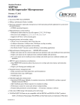
Once the supply voltage is stable and the system clock (MasterClock) has been
cycling for more than 100 msecs, an input signal, VCCOk should be supplied
to the VR4000 (see Figure 2.1). Three points worth noting:
• It is not necessary to have VCC to the chip stable before starting the
MasterClock. Although, it is highly recommended to turn on the
MasterClock before the chip supply is turned on; so that, the internal
dynamic nodes are at rails and thus avoid large initial power
consumption.
• It is also recommended to ramp the power supply slowly to avoid
part from getting “latched up”.
• ColdReset* must be asserted when VCCOk is asserted. The
behavior of the processor is undefined if VCCOk asserts while
ColdReset* is de-asserted.
Once the VCCOk is asserted, the VR4000 begins to drive the ModeClock. This
is an output clock which runs at the frequency of 1/256 of the MasterClock.
and a 50% duty cycle. The ModeClock will be at a high level prior to the
2
VR4000/VR4400 Reset and Initialization Sequence
5.25V
4.75V
VCC
MasterClock
(MClk)
VCCOk
TDS
> 100ms
256
MClk
cycles
256 MClk cycles
ModeClock
TMDS
ModeIn
TMDH
Bit
Bit 0 Bit 1
255
> 100ms
> 64K MClk cycles
TDS
ColdReset*
TDS
> 64 MClk cycles
TDS
TDS
Reset*
MasterOut
Undefined
SyncOut
Undefined
TClock
Undefined
RClock
Undefined
TClock &RClock
stable after
64 MClk cycles
Figure 2.1: Reset Timing diagram.
assertion of VCCOk. The VCCOk signal also remain asserted during this time.
Once VCCOk and ColdReset* are asserted, the ModeClock will be initiated
with the first rising edge occurring 256 MasterClock cycles later. At the rising
edge of every ModeClock a mode bit will be latched in the processor. The serial
PROM which stores the programmed mode bits will have to drive the ModeIn
pin prior to the rising edge of the ModeClock, as per required data setup
(TMDS) and hold time (TMDH).
There are a total of 256 mode bits (see Table 2-1). The values of all the reserved
bits must be set to a logic low or else the operation of the VR4000 is undefined.
After the VCCOk is asserted, the ColdReset* must be held for at least 100msecs
or 64K MasterClock cycle. This conservative number is deliberately chosen in
anticipation of changes in the future and to allow the VR4000, fabricated with
the variety of present and future processes, to function properly. ColdReset*
needs to be de-asserted synchronously with the MasterClock as per specified
data setup and hold time. The de-assertion of the ColdReset* signifies the end
VR4000/VR4400 Reset and Initialization Sequence
Rev1.0
3
of the mode bits initialization, and the beginning of the stable internal clocking
of the VR4000. The ModeClock signal will continue to toggle after reading in
the mode bits until ColdReset* is reasserted.
The bit# 63 of the mode bits allows the user to select the VR4000 to run with
the PLL enabled or disabled (see Table 2-1). The normal operation of the
processor with the PLL disabled is not supported and this mode is used for
debugging of the silicon only. If the PLL is enabled, it will begin locking the
PClock, SClock, RClock, & TClock, to the MasterClock, after the VCCOk is
asserted. The MasterOut and SyncOut will be stable when the ColdReset* is
de-asserted; but the SClock, RClock & TClock will stablize 64 MasterClock
cycles after the ColdReset* is de-asserted1. Although, it could be assumed that,
regardless of which SysCkRatio (mode bits 15:17 in Table 2-1) the system
interface is operating, the rising edge of PClock, SClock, RClock & TClock will
be synchronized to the first rising edge of the MasterClock after the deassertion of the ColdReset* signal.
After the de-assertion of the ColdReset* signal, the Reset* signal needs to be
asserted for at least 64 MasterClock cycles before the VR4000 is completely
reset. However, for the simplicity of design, the Reset* signal can be asserted
at the same time as ColdReset* is asserted and held asserted for at least 64
MasterClock cycles after the ColdReset* is de-asserted. Similar to the
ColdReset*, the Reset* signal must be de-asserted synchronously with the
rising edge of the MasterClock. At the de-assertion of the Reset* signal, the
power-on reset is completed. At this point the VR4000 internal state machines
are reset, and the VR4000 fetches the next instruction from Reset Exception
Vector. All the outputs and the I/Os of the processors are in an undefined state
during all the three reset sequences and there is valid data only when
ValidOut* signal is asserted.
2.1.1.1 Cold Reset
The Cold Reset is same as the power-on reset sequence with two exceptions.
• Power is presumed to be stable before the assertion of the reset
inputs.
• The VCCOk signal needs to be de-asserted.
To initiate the Cold reset sequence, it is necessary to de-assert the VCCOk signal
for at least 100msecs, besides asserting the ColdReset*. All the timings after the
VCCOk signal is re-asserted are same as that shown in the Figure 2.1. The
VCCOk signal is to be pulsed synchronous to the rising edge of the
1. PClock and SClock are internal clocks. For description on the clocks please see ref #2.
4
Rev1.0
VR4000/VR4400 Reset and Initialization Sequence
MasterClock. The sequence of events and the signals involved are the same as
the power-on reset. This reset could be used, for example, to re-synchronize the
clocks in fault tolerant applications.
2.1.1.2 Warm Reset
Warm Reset is executed by asserting the Reset* signal synchronous with the
rising edge of the MasterClock, for at least 64 MasterClock cycles. The
ColdReset* should not be asserted and the VCCOk signal remains asserted.
The supply and the clocks are assumed to be stable and mode bits are not read.
This reset is typically used to reset the state machines after encountering a fatal
error. All processor’s internal state machines are reset and all the registers are
preserved except the Error Exception Program Counter (ErrorEPC) register
and the Status register. Since the processor takes the SoftReset Exception, the
ErrorEPC register contains the restart address from the Program Counter(PC);
also the ERL and the SR bits in the Status register are set to 1. Although the
precise states of the cache and the memory are undefined because their states
depends on whether or not a cache miss sequence was interrupted due to the
reset of the processor’s state machines.
VR4000/VR4400 Reset and Initialization Sequence
5
2.2 Boot-Mode Settings
Table 2-1 lists the processor boot-mode settings and the timing is shown
in figure 2.1. The following rules apply to the boot-mode settings listed in
this table:
•
Bit 0 of the stream is presented to the processor when VCCOk
is first asserted.
•
Selecting a reserved value results in undefined processor
behavior.
•
Bits 65 to 255 are reserved bits.
•
Zeros must be scanned in for all reserved bits.
Table 2-1: Boot-Mode Settings
Serial Bit
0
1
2
3
4
5:6
7
8
6
Value
Mode Setting
BlkOrder: Secondary Cache Mode block read response ordering
0
Sequential ordering
1
Subblock ordering
EIBParMode: Specifies nature of System interface check bus
Single error correcting, double error detecting (SECDED) error
0
checking and correcting mode
1
Byte parity
EndBIt: Specifies byte ordering
0
Little-endian ordering
1
Big-endian ordering
DShMdDis: Dirty shared mode; enables the transition to dirty shared
state on a successful processor update
0
Dirty shared mode enabled
1
Dirty shared mode disabled
NoSCMode: Specifies presence of secondary cache
0
Secondary cache present
1
No secondary cache present
SysPort: System Interface port width, bit 6 most significant
0
64 bits
1-3
Reserved
SC64BitMd: Secondary cache interface port width
0
128 bits
1
Reserved
EISpltMd: Specifies secondary cache organization
0
Secondary cache unified
1
Reserved
VR4000/VR4400 Reset and Initialization Sequence
Table 2-1 (cont.) Boot-Mode Settings
Serial Bit
9:10
11:14
15:17
18
19
20
Value
Mode Setting
SCBlkSz: Secondary cache line length, bit 10 most significant
0
4 words
1
8 words
2
16 words
3
32 words
XmitDatPat: System interface data rate, bit 14 most significant
0
D
1
DDx
2
DDxx
3
DxDx
4
DDxxx
5
DDxxxx
6
DxxDxx
7
DDxxxxxx
8
DxxxDxxx
9-15
Reserved
SysCkRatio: PClock to SClock divisor, frequency relationship between
SClock, RClock, and TClock and PClock, bit 17 most significant
0
Divide by 2
1
Divide by 3
2
Divide by 4
3
Divide by 6 (R4400 processor only)
4
Divide by 8 (R4400 processor only)
5-7
Reserved
SIMasterMd : Master/Checker Mode (see mode bit 42); used in R4400
only.
TimIntDis: Timer Interrupt enable allows timer interrupts, otherwise the
interrupt used by the timer becomes a general purpose interrupt
0
Timer Interrupt enabled
1
Timer Interrupt disabled
PotUpdDis: Potential update enable allows potential updates to be issued.
Otherwise, only compulsory updates are issued
0
Potential updates enabled
1
Potential updates disabled
VR4000/VR4400 Reset and Initialization Sequence
7
Serial Bit
21:24
Value
Mode Setting
TWrSUp: Secondary cache write de-assertion de-assertion delay, TWrSup
in PCycles, bit 24 most significant
0-2
Undefined
3-15
Number of PClock cycles: Min 3, Max 15
Table 2-1 (cont.) Boot-Mode Settings
Serial Bit
25:26
27:28
29
30:32
33:36
37:40
41
8
Value
Mode Setting
TWr2Dly : Secondary cache write assertion delay 2, TWr2Dly in PCycles, bit
26 most significant
Undefined
0
1-3
Number of PClock cycles: Min 1, Max 3
TWr1Dly: Secondary cache write assertion delay 1, TWr1Dly in PCycles, bit
28 most significant
Undefined
0
1-3
Number of PClock cycles; Min 1, Max 3
TWrRc: Secondary cache write recovery time, TWrRc in PCycles, either 0 or
1 cycle
0 cycle
0
1
1 cycle
TDis: Secondary cache disable time, TDis in PCycles, bit 32 most significant
Undefined
0-1
2-7
Number of PClock cycles: Min 2, Max 7
TRd2Cyc: Secondary cache read cycle time 2, TRdCyc2 in PCycles, bit 36
most significant
Undefined
0-2
3-15
Number of PClock cycles: Min 3, Max 15
TRd1Cyc: Secondary cache read cycle time 1, TRdCyc1 in PCycles, bit 40
most significant
Undefined
0-3
4-15
Number of PClock cycles: Min 4, Max 15
0
Reserved
VR4000/VR4400 Reset and Initialization Sequence
Serial Bit
Value
Mode Setting
SCMasterMd : selects the type of Master/Checker mode (also see
description of mode bit 18). Used in R4400 only.
SCMaster
Md
(Bit 42)
42
43:45
0
SIMasterM
d
(Bit 18)
0
0
1
1
1
0
0
1
Mode
Complete Master
(required for single-chip operation)
Complete Listener
(paired with Complete Master)
System Interface Master
(SIMaster)
Secondary Cache Master
(SCMaster, paired with SIMaster)
Reserved
Table 2-1 (cont.) Boot-Mode Settings
Serial Bit
46
47:49
50:52
53:56
Value
Mode Setting
Pkg179: R4000 Processor Package type
Large (447 pin)
0
1
Small (179 pin)
CycDivisor: This mode determines the clock divisor for the reduced
power mode. When the RP bit in the Status register is set to 1, the pipeline
clock is divided by one of the following values. Bit 49 is the most
significant.
Divide by 2
0
Divide by 4
1
2
Divide by 8
3
Divide by 16
4-7
Reserved
Drv0_50, Drv0_75, Drv1_00:
Drive the outputs out in n x MasterClock
period. Bit 52 is the most significant. Combinations not defined below are
reserved.
1
Drive at 0.50 x MasterClock period
2
Drive at 0.75 x MasterClock period
4
Drive at 1.00 x MasterClock period
InitP: Initial values for the state bits that determine the pull-down ∆i/∆t
and switching speed of the output buffers. Bit 53 is the most significant.
0
Fastest pull-down rate
1-14
Intermediate pull-down rates
15
Slowest pull-down rate
VR4000/VR4400 Reset and Initialization Sequence
9
Serial Bit
57:60
61
62
10
Value
Mode Setting
InitN: Initial values for the state bits that determine the pull-up ∆i/∆t and
switching speed of the output buffers. Bit 57 is the most significant.
0
Slowest pull-up rate
1-14
Intermediate pull-up rates
15
Fastest pull-up rate
EnblDPLLR: Enables the negative feedback loop that determines the
∆i/∆t and switching speed of the output buffers during ColdReset.
0
Disable ∆i/∆t mechanism
1
Enable ∆i/∆t mechanism
EnblDPLL: Enables the negative feedback loop that determines the ∆i/∆t
and switching speed of the output buffers during ColdReset and during
normal operation.
0
Disable ∆i/∆t control mechanism
1
Enable ∆i/∆t control mechanism
VR4000/VR4400 Reset and Initialization Sequence
Table 2-1 (cont.) Boot-Mode Settings
Serial Bit
63
64
65:255
Value
Mode Setting
DsblPLL: Disables the phase-locked loops (PLLs) that match
MasterClock and produce RClock , TClock, SClock , and the internal
clocks.
Enable PLLs
0
1
Disable PLLs
SRTristate: Controls when output-only pins are tristated
0
Only when ColdReset* is asserted
1
When Reset* or ColdReset* are asserted
Reserved. Scan in zeros.
VR4000/VR4400 Reset and Initialization Sequence
11
Initialization
3
When the power is turned on to a system, it goes through a boot sequence. This
power up boot sequence includes resetting the CPU and other external chips and
initializing registers, caches and memory both inside and outside the CPU.
Details of the initialization of components external to the VR4000, except the
secondary cache, is outside the scope of this application note and so the topic
is not included.
In a VR4000 system, when the power is turned on, the external hardware
asserts VCCOk, ColdReset* and Reset* and holds them for the required
period, as described in the previous section. This initiates the sequence which
loads the mode bits, enables the PLL to lock all the internal clocks to the
MasterClock and resets internal registers and state machines. After the Reset*
is de-asserted by the external logic, the VR4000 will take an exception and will
fetch the next instruction from a Reset Exception handler, residing in a PROM.
The code in the handler will initialize all the internal and external registers,
caches and memory. The following section gives a guideline, using pseudo
code, on the sequence of tasks that the code in the handler would perform.
Note that this pseudo code is intended to show how the VR4000 reset and
initialization fits in the system booting procedure and it is not intended to
cover all the aspects of system initialization. The topics of cache initialization
and TLB initialization are covered in detail, in section 3.2 & 3.4, respectively,
to allow the programmer to write proper routines to perform the tasks.
3.1 Pseudo code for Reset Exception Handler
Initialization() {
If {Warm Reset}
/* Start at address 0xbfc0 0000 */
{
Save the Important registers and Status;
}
Initialize all the General Purpose registers
Initialize the Status register;
/* The 32 or 64 bit mode, BEV mode, Interrupts disabled or masked, Reverse-endianness,
CPU operating mode, Coprocessor enabled, etc. are set in the Status register */
11
VR4000/VR4400 Reset and Initialization Sequence
Initialize the Config register;
/* Primary I & D cache line sizes,
kseg0 cache coherency attributes, etc.) */
Initialize the Cause register;
/* Disable software interrupts */
Initialize FPU control register;
Initialize the various components external to the CPU;
/* Physical memory banks, Video RAM,
refresh rate, interrupts, security */
Initialize and Configure the Primary, Instruction and Data caches and
Secondary caches if any;
/* See section 3.2 on page 13 for detail */
Initialize the ITLB & JTLB;
/* See section 3.4 on page 17 for detail */
Initialize other ports like Interrupt Controller, Serial I/O, keyboard, EISA, graphic device, etc.
/* The following code does not need to be part of the initialization process */
Configure Memory and Setup Exception handling in normal mode;
if (DIAG Flag is ON & (Power On Reset or Cold Reset)) {
Run Power On Diagnostics();
if (Fatal Error)
{
Display error and Halt;
/* Can’t proceed*/
Store the diagnostics status in NVRAM;
}
}
Give the control to Stand-alone shell or PROM based monitor;
}
12
VR4000/VR4400 Reset and Initialization Sequence
3.2 Cache Initialization
3.2.1 Cache state during boot-up
The contents of the caches are undefined at the end of any of the three reset
sequences, described in section3.1. Since the reset exception is located in the
unmapped and uncached address space, kseg1, it is not necessary to initialize
the cache and TLB to handle Reset Exceptions. Typically, most or all of the
initialization routines, “Diagnostic Firmware” and “Firmware Monitor”
should run from the unmapped address space.
3.2.2 Configuration and Invalidation
The caches are undefined when the reset sequence takes place, they have to be
configured, which means that the size and state of the cache lines for both
primary and secondary caches (if present) must be defined, before using them.
Some parameters need to be fed via the Serial Boot PROM and hence the
parameters cannot be changed and others are defined by writing into the
config and status registers. Also whether the contents of the ECC register are
used to set or modify the check bits of the caches and whether the cache parity
or ECC errors can cause exceptions is determined by the bits CE and DE of the
Status register respectively (for detail see ref# 2).
The Configuration parameters can be summarized as
• Split or Unified Secondary cache for Data and Instruction
• Secondary cache size
• Secondary cache present or absent
• Primary I cache size
• Primary D cache size
• Primary I cache line size
• Primary D cache line size
• System Interface ECC or parity mode selection
• Using contents of ECC register to set or modify check bits of caches
• Whether cache parity or ECC error can cause exceptions
VR4000/VR4400 Reset and Initialization Sequence
13
The caches in an undefined state can have random values for all the fields
including the check-bits and the state-bits. So, it is not enough to just invalidate
the line; but, data and tag fields need to be loaded. As the data and the Tags
are written, the processor will also write the correct corresponding check bits
in the cache. Thus, it is necessary that the error checking be turned off before
the initialization process is started or the processor might keep taking the
Cache Error Exception. It is also critical that all the secondary cache tag bits(17
to 35) be loaded with a correct physical tag, regardless of the size of the
secondary cache; because the processor always compares all the tag bits. The
caches are written using the TagLo and TagHi registers with a combination of
various “CACHE OP” instructions. The following pseudo code shows an
example of the cache initialization sequence. This code needs to be in the
Unmapped, Uncached address space (kseg1). This code may reside in a PROM.
3.3.3 Cache Initialization Pseudo Codes
/* The cache implementation in VR4000 requires that to initialize all the tags, the PCache line size
must be minimum (4 words); so before the initialization, if the line size is greater than four words,
one might need to save the Config register in CP0, change the PCache line size to minimum and
then restore the Config register after the initialization is completed. */
Status[DE]= 1
/* Turn the Cache Error detection off */
Config -> GPR[Orig]
/* Use MFC0 to save the Config register */
Config[IB,DB] <- 4 words
/* Use MTC0 instruction to program minimum PCache line size.*/
InitializeCache()
#define
BaseAdd
0x80000000
(0xFFFF FFFF 8000 0000 for 64 bit mode)
#define
SJ_CASIZE
(Joint SCache size in the system)
/ * The following cache & line sizes should have been set in the Config register during boot
*/
/ * PD_CACSIZE & PI_CACSIZE are sizes of the two primary Caches */
/ * PD_LINESIZE & PI_LINESIZE are line sizes of the two primary Caches (modified to minimum - 4 words - for the initialization process) */
/ * SJ_LINESIZE is the secondary cache line size */
/ *Macro definitions */
/ * This macro performs the Cache Operation on primary D/I caches. */
#define
PCACHE (Cache_op, CacheAdd, P_CACSIZE, P_LINESIZE)
CurrAdd = CacheAdd;
VR4000/VR4400 Reset and Initialization Sequence
14
EndAdd = BaseAdd + P_CACSIZE;
while (CurrAdd < EndAdd)
{Do Cache_op on CurrAdd;
CurrAdd += P_LINESIZE;}
/* This macro performs the Cache Operation for the tags of the joint secondary cache. Load
tag fields with suitable values.*/
#define
SCACHE (Cache_op, CacheAdd, P_CACSIZE, SJ_LINESIZE)
CurrAdd = CacheAdd;
EndAdd = CacheAdd + P_CACSIZE;
TagLo[SState] = Dirty Exclusive;
while (CurrAdd < EndAdd)
{
TagLo[Vindex] = CurrAdd[14...12]; /* Set TagLo register with the data to be
*/
TagLo[STagLo] = CurrAdd[35...17]; /* To transfer into the SCache Tag, independent of the SCache size */
Do Cache_op on CurrAdd;
CurrAdd += SJ_LINESIZE;
}
Initialize SJCache()
/* Also initialize PDCache in the pro-
cess */
{Vir_Add = BaseAdd
while (Vir_Add < BaseAdd + SJ_CASIZE)
{/*
Load8K bytes (16K for R4400) of SCache with valid SCTag address */
SCACHE (Index_StoreTag_SJ, Vir_Add, PD_CACSIZE, SJ_LINESIZE)
/* Next set up the PD Cache tag */
TagLo[PState] = Dirty Exclusive;
/* Set TagLo register with the data to be
TagLo[PTagLo] = Vir_Add[35...12];
/* transferred into the SCache Tag */
*/
PCACHE (Index_StoreTag_PD, Vir_Add, PD_CACSIZE, PD_LINESIZE)
/* Next deposit zeros into Data field of PD cache (with correctly generated check bits) in 8
Bytes chunks */
PCACHE (SD r0 Vir_Add, Vir_Add, PD_CACSIZE, 0x8)
/* Next writeback the PD cache line into the joint SCache (ECC generated) and invalidate
the line in the PDCache */
PCACHE (Index_WriteBack_Inv, Vir_Add, PD_CACSIZE, PD_LINESIZE)
VR4000/VR4400 Reset and Initialization Sequence
15
Vir_Add += PD_CACSIZE;
}
/* Repeat the steps to initialize the next 8K (16K for R4400) of SCache */
}
16
VR4000/VR4400 Reset and Initialization Sequence
Initialize PICache()
{
Vir_Add = BaseAdd;
/* 0x80000000*/
/* Next load TagLo register with suitable values for initializing PI_cache*/
TagLo[PState field] = Invalid;
TagLo[PTag field] = 0
/* Next call the macro for storing the TagLo info into the PI cache*/
PCACHE (Index_StoreTag_PI, Vir_Add, PI_CACSIZE, PI_LINESIZE)
/* Next fill the data field of the PICache with zeros and invalidate the line */
while (Vir_Add < BaseAdd + PI_CACSIZE)
{FILL CacheAdd
Hit_Inv_PI
/* Fill zeros in the PICache data fields from the SCache*/
/* Invalidate the PI cache line*/
CacheAdd += PI_LINESIZE }
}
GPR[Orig] -> Config
/* Restore the original line sizes of the primary caches*/
3.3.4 Cache Error handling
The DE bit in the Status register determines whether the processor will take
exception due to any cache error. The Cache Error Exception handler must be
set up prior to clearing the DE bit. The Cache Error exception vector is located
in the uncached address space (see ref# 2 for more information).
VR4000/VR4400 Reset and Initialization Sequence
17
3.4 TLB Initialization
The VR4000 has an on-chip Memory Management Unit (MMU) that includes
the Translation-Look-Aside Buffer(TLB) and CP0 registers. Besides the
mapping of virtual page number(VPN) to physical frame number(PFN), every
TLB entry can be programmed with the corresponding virtual page size and a
page attribute to define the cache coherency mechanism. Depending upon the
version of VR4000 (PC, SC or MC), five different page attributes can be used.
They are as follows:
• Uncached
(PC,SC,MC)
• Cacheable noncoherent
(PC,SC,MC)
• Cacheable coherent exclusive
(MC)
• Cacheable coherent exclusive on write
(MC)
• Cacheable coherent update on write
(MC)
Please refer to the VR4000 Microprocessor User’s Manual or MIPS R4000
Microprocessor User’s Manual for a detail description of the TLB.
Like the caches, the TLB is in an undefined state after any of the three reset
sequences is completed. Since the Reset Exception Vector is in an unmapped,
uncached space, the TLB can be initialized by the code from the handler,
without using the TLB. There are various TLB instructions and CP0 registers
as part of the on-chip MMU to provide software support to the TLB. In the
sections that follow the guidelines and the pseudo code on how TLB is to be
initialized are presented.
3.4.1 Procedure to write into the TLB
Writing into a specific entry of the TLB is supported by the TLBWI instruction
and the following CP0 registers: Index, ENHI, ENLO0, ENLO1 and PageMask
(see ref#2 for detail). The index register allows access to any of the 48 TLB
entries (0 to 47) by pointing to the entry specified by the lower six bits of the
register. The TLBWI instruction transfers to the entry selected by the Index
register, the contents of ENHI register (VPN & ASID) to the tag field of the TLB
and the contents of ENLO0 and ENLO1(even and odd PFN and page
attributes) to the data field of the TLB, respectively. During the write, the value
from the PageMask register is also used to encode the virtual page size into the
tag part of the TLB. The basic technique to write into a TLB entry is to move
the appropriate values into these CP0 registers using mtc0 instruction; and
then invoke the TLBWI command to transfer the values into the TLB entry,
selected by the content of the TLB Index register. This procedure is to be
repeated 48 time to fully initialize the whole TLB. A note of caution, if the VPN
is in mapped address space, the value of this field has to be different for the
different TLB entries. The same VPN in more than one TLB entry will cause
18
VR4000/VR4400 Reset and Initialization Sequence
undefined TLB mapping operations and possibly cause a TLB shutdown. The
virtual address from unmapped space disables the TLB mapping operation.
The only way to recover from the TLB shutdown is to assert the Reset* signal.
Codes written to initialize the TLB can be included as part of the reset handler.
This will allow the processor to initialize the TLB every time a reset is issued.
3.4.2 ITLB Initialization
The VR4000 has a separate Instruction TLB (ITLB) which contains a copy of
two instruction entries of the TLB. Although the ITLB is transparent to the
user, it is recommended to initialize it during boot time. Not initializing the
ITLB will not cause any functional problem; however, it might cause the
processor’s behavior to be indeterministic1. The method to initialize the ITLB
is indirect but relatively simple. Since the ITLB cannot be accessed like the
TLB, executing a jump instruction from an uncached, unmapped space at the
end of the initialization sequence to an address in an uncached, mapped space;
and, subsequently, executing several NOP’s effectively initializes the ITLB. A
jump is required from two different TLB entries, with different VPN so that
both ITLB entries would get initialized. The pseudo code below shows an
example of how the TLB and the ITLB can be initialized.
3.4.3 Pseudo Code exemplifying TLB and ITLB initialization
/* VR4000 TLB/ITLB Initialization Pseudo code in the unmapped region */
TLBInit()
{
Entry = 0;
/* TLB Entry number */
ENHI, ENLO0/1, INDEX, PGMASK & WIRED = 0’s;/*Use mtc0 instruction and r0 register*/
while (Entry < 48)
{TLBWI
/* Write into the TLB entry pointed by
INDEX register */
ENHI += 1
/* Each entry must have a different VPN or ASID regardless of whether the entry is valid
or not. More than one TLB entry with the same TAG field will cause R4000 to enter into an undefined state or even a TLB shutdown. Since the G Bit is 0, incrementing ASID (8 LSBs of ENHI) is sufficient; but one can also provide unique TAG in each entry by incrementing VPN2 (ENHI += 0x2000)
*/
Entry += 1
INDEX <- Entry;
/* Use mtco instruction */
1. This might be a problem only if more than one processor are operated in lock step; for
example, in fault tolerant systems.
VR4000/VR4400 Reset and Initialization Sequence
19
}
/* Following pseudo code is to initialize the two ITLB entry */
ENHI = VA1, ENLO0/1 = (PA1, uncached, Valid)/* VA1 & PA1 in mapped region*/
INDEX = X1
/* Any entry */
TLBWI;
/* Map a TLB entry X1 with mapped
uncached address */
r1 = VA1;
/* In any mapped region */
JR r1;
/* Jump to the uncached, mapped address stored
in r1 to initialize one of the ITLB entries */
PA1: ENHI = VA2, ENLO0/1 = (PA2, uncached, valid)/* VA2 & PA2 in mapped region */
INDEX = X2
/* Any entry other than X1 */
TLBWI;
/* Map entry X2 with mapped uncached address */
r1 = VA2;
JR r1;
PA2:
NOP;
NOP;
NOP;
}
/* Now the program can jump to mapped, cached address space if the caches are initialized.
*/
20
VR4000/VR4400 Reset and Initialization Sequence
3.5 Other system level initialization
Once the TLB and the caches are initialized, the VR4000’s initialization is
complete and other system level initialization for components like memory,
ASIC chipset, etc. can begin using the TLB and caches.
VR4000/VR4400 Reset and Initialization Sequence
21
Summary
4
Two major aspects of the boot sequence for the VR4000 were described in this
document. The three reset sequences - Power_on Reset, Cold Reset, and Warm
Reset were described in chapter 2 and the procedures for initializing both
primary and secondary caches and the two TLBs were described in chapter 3.
The reset sequences are controlled by the hardware (internal and external to
the chip) and the initialization of the caches, TLBs and CP0 registers are
controlled by the software residing in the Reset Exception handler. Power_on
Reset sequence is a super set of the three sequences. It is initiated when poweron is indicated by the VCCOk signal and begins by resetting the PLL and thus
starting all the clocks; then, starting the ModeClock and in turn feeding the
mode bits into the processor and finally, resetting all the internal state
machines and key registers. The Cold Reset sequence is initiated by asserting
the ColdReset* signal. The power is stable when this sequence begins; but, the
PLL is reset so the clocks are restarted, the mode bits are read into the
processor again and the processor’s internal state machines are also reset. The
Warm Reset is initiated by the assertion of the Reset* signal. This sequence does
not affect the clocks or the mode bits but only reset the internal state machines.
All the three sequences end with taking exceptions. The first two sequences
takes Reset Exception and the third one takes the SoftReset Exception; but the
processor, in all the three cases, jumps to the same exception vector (ref# 2).
The initialization of the mode bits, during the boot time, provides a great
amount of flexibility to users in terms of processor configuration and
operating parameters. These mode bits were described in chapter 2 (Table 2-1).
The initialization of caches and TLBs is done from the exception handler and
the procedure was described via a pseudo code. The cache initialization
description included the procedure to initialize the instruction and data
caches, both for the on chip (primary) and off the chip (secondary) caches.
There is also a separate instruction TLB (ITLB) on the chip, besides the regular
TLB (JTLB), that needs to be initialized. This ITLB is not directly accessible to
the user; and thus, it is initialized by causing an internal ITLB fill with
instructions in the mapped, uncached region, before jumping to the mapped,
cached region.
VR4000 Reset and Initialization Sequence
21
References
5
Reference 1: MIPS R4000 Processor Interface Specification
Reference 2: MIPS R4000 Microprocessor User’s Manual
22
R4000 Reset and Initialization Sequence
VR4000 Reset and Initialization Sequence
23
Reader’s Comments
Please FAX your comments about this document to:
Anjaneya Thakar: Fax: (415) 390-6170
Address: P.O. Box 7311, MS 952, Mountain View, CA 94039-7311
Areas of Improvement:
Errors:
Reader Information:
Name:
Company:
Address:
Phone:
FAX:
Thank you for your feedback.
24
VR4000/VR4400 Reset and Initialization Sequence