1
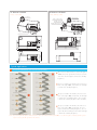
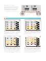
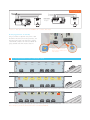
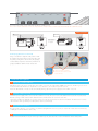
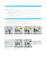
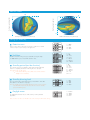
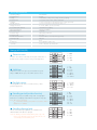
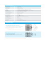
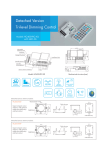
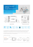
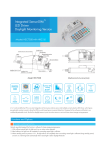
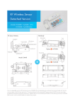
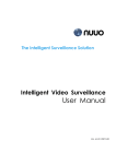
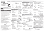
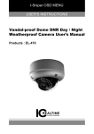
Sensors with RF Wireless Transmission Control Model: HC028V/RF, HC018V/RF HC023RF, HC024RF This is a combination of motion sensor and RF radio wave wireless transmission, which is perfect solution for retrofit projects. The motion detected by 1 sensor (the master unit) can pass onto other pre-defined individuals (the slave units) though RF transmission. The master can trigger unlimited number of slaves as long as within the transmission range (30 meters indoor and 100 meters in the open area). With fixed address code technology, it’s easy to set up transmission groups. Up to 16 different groups can be created. Optional transmission frequency of 433/868 MHz, thanks to FSK technology. Easy installation and free of wiring! -PPQJO 5. -PPQPVU %BZMJHIU .POJUPSJOH .)[ "NCJFOUEBZMJHIU UISFTIPME 3PUBSZ4XJUDI (SPVQJOH %FUFDUJPO1BUUFSO Master ter Mas IPVST NBOVBMPO RF Transceiver HC028V/RF _-VY $POEPNJOJVN DPOUSPM RF Transmitter HC018V/RF *can serve as both master and slave Detection area )PMEUJNF T_NJO RF antenna Hold-time *master only RF Antenna Antenna module Detection area LED indication Daylight sensor Hold-time Rotary coding switch(TX) Daylight threshold Daylight sensor Stand-by period Stand-by period Stand-by dimming level Rotary coding switch(RX) Stand-by dimming level Brightness on RF signal LED indication Push Daylight sensor Rotary coding switch 86.5 93.2 102 28 27.5 99 105.7 114.5 4.2 4.2 45 45 1-10V 54 10% or 100% Mas ter RF Receiver HC023RF RF Receiver HC024RF *slave, on-off control *slave, dimming control RF antenna RF antenna Rotary coding switch Stand-by period Stand-by dimming level 4.2 4.1 38 37.5 Rotary coding switch 71.5 78.2 87 38.3 25 38.3 25 66.5 73 82 Typical Applications 1 For staircase (HC028V/RF serves as both master and slave) 1 The 1st sensor detects motion, it turns the light on 100% and sends signal to the 2nd sensors at the same time. The 2nd light is switched to stand-by brightness. 2 The person walks to the 2nd floor, the 2nd sensor turns on the light 100%, meanwhile, the 3rd light is switched to stand-by brightness. 3 The person walks to the 3rd floor, the 3rd sensor turns on the light 100%, meanwhile, the 4th light is switched to stand-by brightness. The 1st light is dimmed to stand-by brightness after hold-time. 4 The person walks to the 4th floor, the 4th sensor turns on the light 100%, meanwhile, the next light is switched to stand-by brightness. The 1st light is off after stand-by period and the 2nd light is dimmed to stand-by brightness. Note: by selecting the brightness DIP switch, the slave can either turn the light 100% on or dim the light to stand-by dimming level upon receiving the RF signal from the master. RF Grouping (Maximum 16 channels) Using a screwdriver to adjust the rotary switch on both the tranmiter unit (master) and receiving unit (slave), and keep them pointing at the same channel, the grouping is automatically completed. 16 channels (maximum 16 groups) available for both the master & slave unit. master slave Note: RX1 and RX2 receive two different RF signals from two different masters. Using a screwdriver to point the arrow to the same channel on both master and slave. 2 For staircase and corridor (HC028V/RF as both master and slave, HC024RF as slave) HC024RF (slave) HC028V/RF 1 HC024RF (slave) HC028V/RF Off Off Off Off Off Off Off Off Off Off Off 10% Off Off 10% 100% 100% 100% 100% 100% 100% 100% 100% Corridor 2 Corridor While the 1st sensor detects motion on the 1st floor, it The person walks to the 2nd floor, the 2nd HC028V/RF switches the light on 100% and sends signal to all slave switches the light on 100%. All HC024RF on the 2nd floor units. All HC024RF on the 1st floor turn on 100% and the turn the light on 100% and the HC028V/RF on the 3rd HC028V/RF on the 2nd floor goes to stand-by level. floor goes to stand-by level. HC024RF (slave) HC028V/RF 3 HC024RF (slave) HC028V/RF Off Off 10% 100% 100% 100% 100% 100% 100% 100% 100% 100% 10% 10% 10% 10% 10% Off Off Off 10% Corridor 4 100% Corridor When walks to the 3rd floor, the 3rd HC028V/RF The person walks to the 4th floor, the 4th HC028V/RF switches the light on 100%. All HC024RF on the 3rd floor switches the light on 100%. All HC024RF on the 4th floor turn the light on 100% and the HC028V/RF on the 4th turn the ligh on 100% and the next HC028V/RF goes to floor goes to stand-by level. Meanwhile, the lights on the stand-by level. Meanwhile, all sensors on the 1st floor turn 1st floor are dimmed to stand-by level after hold-time. the light off after stand-by period, and all lights on the 2nd Note: the lights in the corridor go off directly after hold-time when controlled by HC023RF. floor dim to stand-by level after hold-time. Wiring Diagram 220~240VDC 220~240VDC ))))))))))))))))) LED driver LED driver RF Signal HC024RF HC028V/RF LED LED Note: this 1-10V output on the master unit HC028V /RF is isolated, SELV output. RF Grouping (Maximum 16 channels) Using a screwdriver to adjust the rotary switch on both the tranmiter unit (master) and receiving unit (slave), and keep them pointing at the same channel, the grouping is automatically completed. 16 channels (maximum 16 groups) available for both the master & slave unit. slave master Using a screwdriver to point the arrow to the same channel on both master and slave. 3 For carpark (HC018V/RF as master and HC024RF as slave) master slave slave slave slave slave master slave slave master With sufficient natural light, the sensor is not triggered by motion. master slave slave slave With insufficient natural light, the sensor is triggered by motion, the master switches on the light and send RF signal to all salves. master slave slave slave slave slave master After the hold-time, the whole group of lamps dim to pre-defined dimming level when no movement detected. Note: the lights go off directly after hold-time when controlled by HC023RF. slave slave slave slave slave master master The whole group of lamps switch off automatically after the stand-by period. Note: even in case the slave fails to receive the off signal from the master, it will also switch the light off automatically after a 30min time delay. Wiring Diagram 220~240VDC 220~240VDC ))))))))))))))))) LED Driver HC018V/RF RF Signal HC024RF LED LED Driver LED RF Grouping (Maximum 16 channels) Using a screwdriver to adjust the rotary switch on both the tranmiter unit (master) and receiving unit (slave), and keep them pointing at the same channel, the grouping is automatically completed. 16 channels (maximum 16 groups) available for both the master & slave unit. slave master Using a screwdriver to point the arrow to the same channel on both master and slave. Functions and Options 1 8H manual on mode for LED lamp Rapidly turn off/on the power supply three times within 3 seconds, the light will be 100% on for 8 hours, and then goes to sensor mode automatically after 8 hours. Useful when sensor function is not needed in special occasion. Note: this 8H manual on mode can be cancelled by turning off/on the power supply one time within 1second. 2 Ambient daylight threshold Switch the power supply to the sensor two times within 2 seconds, the sensor can set the ambient lux level as the new threshold. Both the settings on DIP switch and the ambient lux threshold learned can over write each other. This feature enables the daylight sensor to be commissioned to the environment in which it is installed. The latest action controls. (More details of the operation procedure please refer to user manual). 3 Zero-cross relay operation Designed in the software, sensor switches on/off the load right at the zero-cross point, to ensure the in-rush current is minimised, enabling the maximum lifetime of the relay. 4 Loop-in and loop-out terminal Double L N terminal makes it easy for wire loop-in and loop out, and saves the cost of terminal block and assembly time. 5 Manual override (for HC028V/RF only) This sensor reserves the access of manual override function for end-user to switch on/off, or adjust the brightness by push-switch, which makes the product more user-friendly and offers more options to fit for some extra-ordinary demands: * Short push (<1s): on/off function; On → off: the light turns off immediately and can not be lighten for a certain time (equals to hold-time preset) even movement is detected. After this period, the sensor goes to sensor mode. Off → on: the light turns on and goes to sensor mode, no matter if ambient Lux level exceeds the daylight threshold or not. Meanwhile, it will send RF signal to all slaves. * Long push (>1s): dim up/down the hold-time brightness between 10% and 100%. Both the settings on DIP switch and manual override can overwrite each other, the latest action controls. Note: if end-user do not want this manual override function, just leave the “push” terminal alone and don’t connect it to any wire. 6 Daylight monitoring function (for HC028V/RF and HC018V/RF) Hytronik specially designed this function in software for deep energy-saving purpose: 1. With sufficient natural light, the light won’t turn on when motion detected. However, the master still sends out RF signals to slave unit(s). 2. After hold-time, the light turns off completely if surrounding natural light is sufficient. 8 3. When stand-by period is preset at “+ ”, the light will turn off completely when surrounding natural light is sufficient during stand-by period, and turn on at dimming level automatically when natural light is below daylight threshold. 1 2 15:00 17:30 3 17:35 With sufficient natural light, the light does not switch on even At dusk,as the natural light drops below threshold value, The light switches on at 100% when there is movement there is movement detected. the sensor turns on the light at detected. 4 17:50 Light dims to stand-by level after the hold-time. the dimmed level. 5 08:00 3 4 6 09:30 goes in cycle during the night ... Settings on this demonstration: Hold-time 10min Daylight threshold Stand-by period Stand-by dimming 50lux +∞ level 100% on when movement detected, and dims to10% in At dawn, light turns off completely when natural light Light does not switch on even when movement detected long absence. reaches above daylight threshold. during the daytime. 10% Detection Pattern 50% 75% 10% 30% Wall mounted height (m) 10% 30% 50% 75% Ceiling mounted detection pattern (m) Wall mounted detection pattern (m) Settings (HC028V/RF) 1 Detection area 100% Detection area can be reduced by selecting the combination on the DIP switches to fit precisely for each specific application. 75% 50% 10% 2 5s 30s 1min 5min 10min 20min 30min Hold-time Hold-time means the time period you would like to keep the lamp on 100% after the person has left the detection area. 3 Stand-by (corridor function) Functions andperiod Options This is the time period you would like to keep at the low light output level before it is completely switched off in the long absence of people. Note: “0s” means on/off control; “+ ”means bi-level dimming control, fixture never switches off when daylight sensor is disabled. 8 Ceiling mounted height(m) 4 Stand-by dimming level This is the dimmed low light output level you would like to have after the hold-time in the absence of people. Note: the stand-by period and stand-by dimming level set up on the master is only valid for the master unit; the slave unit can set its own stand-by period and dimming level. 5 I II III IV V VI VII VIII Daylight sensor The daylight threshold can be set on DIP switches, to fit for particular application. Note: end-user can also scan the QR code on the housing for DIP switch settings. I II III IV I II III IV 1 2 3 1 2 1 2 0s 10s 1min 5min 10min 30min 1h + 10% 20% 30% 50% Disable 50Lux 10Lux 2Lux I – 100% II – 75% III – 50% IV – 10% I – 5s II – 30s III – 1 min IV – 5 min V – 10 min VI – 20 min VII – 30 min I – 0s II – 10s III – 1min IV – 5 min V – 10 min VI – 30 min VII – 1H VIII – +∞ I – 10% II – 20% III – 30% IV – 50% I – Disable II – 50Lux III – 10Lux IV – 2Lux Technical Data (HC028V/RF) Operating voltage 220-240VAC Switched power 400W Coding Fixed address coding (rotar y coding switch for grouping) Detection area 10% /50% /75% /100%, can be customized Hold-time 5s/30s/1min/5min/10min/20min/30min, can be customized Stand-by period 0s/10s/1min/5min/10min/30min/1hour / +∞ Daylight threshold 2~50 lux, disable, can be customized RF. Communicatin Channels 16 channels for grouping Microwave frequency 5.8GHz+/-75MHz Microwave power <0.2mW Detection range Max. (DxH ): 12m x 6m O Detection angle 30~150 RF. Transmission distance 30 meters indoor, 100 meters in the open area Mounting height Max. 6m Tc 80 C RF frequency 433/ 868 MHz (FSK mode) Certificate Semko, CB, EMC, CE, R&TTE, SAA o Settings (HC018V/RF) 1 1 Detection area Detection area can be reduced by selecting the combination on the DIP switches to fit precisely for each specific application. 100% II 75% III 50% IV 10% 1 2 Hold-time Hold-time means the time period you would like to keep the lamp on 100% after the person has left the detection area. 3 4 Stand-by period (corridor function) This is the time period you would like to keep at the low light output level before it is completely switched off in the long absence of people. 8 Note: the stand-by period and stand-by dimming level set up on the master is only valid for the master unit; the slave unit can set its own stand-by period and dimming level. III – 50% IV – 10% 5S 30S 1min 5min 10min 20min 30min I – 5S II – 30S III – 1 min IV – 5 min V – 10 min VI – 20 min VII – 30 min I Disable II 50 lux III 10 lux IV 2 lux I – Disable II – 50 lux III – 10 lux IV – 2 lux III IV V VI Ⅶ 1 1 2 2 3 0S 10S 1min 5min 10min 30min 1h + I II III IV V VI VII VIII Stand-by dimming level This is the dimmed low light output level you would like to have after the hold-time in the absence of people. II – 75% 1 I – 0S II – 10S III – 1 min IV – 5 min V – 10 min VI – 30 min VII – 1 h VIII – 8 5 I – 100% + Note: “0s” means on/off control; “+ ” means bi-level dimming control, fixture never switches off when daylight sensor is disabled. 2 3 I II Daylight sensor The daylight threshold can be set on DIP switches, to fit for particular application. 2 I 2 I 10% II 20% III 30% IV 50% I – 10% II – 20% III – 30% IV – 50% Technical Data (HC018V/RF) Operating voltage 220~240VAC Switched power Capacitive:400W Stand-by power < 0.5W (HC018V/RF) Coding Fixed address coding (rotar y coding switch for grouping) Detection area 10/50/75/100%, can be customized Hold-time 5s/30s/1min/5min/10min/20min/30min, can be customized Daylight threshold 2~50Lux, disable, can be customized RF. Communicatin Channels 16 channels for grouping Microwave frequency 5.8GHz +/-75MHz Microwave power < 0.2mW Detection range Max. ( Detection angle 30~150 RF. Transmission distance 30 meters indoor, 100 meters in the open area. Mounting height Max. 6m Operating temperature -35 C ~ +70 C RF frequency 433 MHz (FSK mode) Certificate Semko, CB, EMC, CE, R&TTE, SAA o x H ): 12m x 6m o o Settings (HC024RF) Stand-by period (corridor function) This is the time period you would like to keep at the low light output level beforeit is completely switched off in the longabsence of people. Note: “0s” means on/off control; “+∞”means bi-level dimming control, fixture never switches off. Stand-by dimming level This is the dimmed low light output level you would like to have after the hold-time in the absence of people. 1 2 3 I II III IV V VI VII VIII 1 0s 10s 1min 5min 10min 30min 1h + 2 I 10% II 20% III 30% IV 50% Note: end-user can also scan the QR code on the housing for DIP switch settings. I – 0s II – 10s III – 1 minute IV – 5 minutes V – 10 minutes VI– 30 minutes VII– 1 hour VIII– +∞ I – 10% II – 20% III – 30% IV – 50%