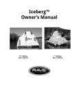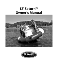
1
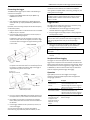
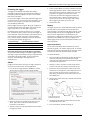
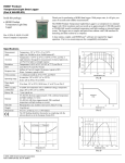
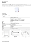
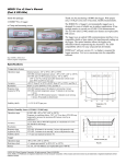
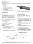
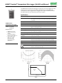
HOBO® Pendant® Temperature Data Logger (UA-001-xx) Manual
The HOBO Pendant Temperature Data Logger is a waterproof, one-channel logger with 10-bit
resolution and can record up to approximately 6,500 (8K model) or 52,000 (64K model)
measurements or internal logger events. The logger uses a coupler and optical base station
with USB interface for launching and data readout by a computer.
Specifications
Measurement Range
-20° to 70°C (-4° to 158°F)
Alarms
High and low alarms can be configured for total amount of contiguous or
non-contiguous time outside of user-defined limits between -20° and 70°C
(-4° to 158°F)
Accuracy
±0.53°C from 0° to 50°C (±0.95°F from 32° to 122°F), see Plot A
HOBO Pendant
Temperature Data Logger
Resolution
0.14°C at 25°C (0.25°F at 77°F), see Plot A
Drift
Less than 0.1°C/year (0.2°F/year)
Models: UA-001-08
UA-001-64
Response Time
Airflow of 2 m/s (4.4 mph): 10 minutes, typical to 90%
Water: 5 minutes, typical to 90%
Time Accuracy
±1 minute per month at 25°C (77°F), see Plot B
Operating Range
In water/ice: -20° to 50°C (-4° to 122°F)
In air: -20° to 70°C (-4° to 158°F)
Water Depth Rating
30 m from -20° to 20°C (100 ft from -4° to 68°F), see Plot C
NIST Traceable
Certification
Available for temperature only at additional charge; temperature range
-20° to 70°C (-4° to 158°F)
Battery Life
1 year typical use
Memory
UA-001-08: 8K bytes (approximately 6.5K sample and event readings)
UA-001-64: 64K bytes (approximately 52K sample and event readings)
Materials
Polypropylene case; stainless steel screws; Buna-N o-ring
Weight
15.0 g (5.3 oz)
Dimensions
58 x 33 x 23 mm (2.3 x 1.3 x 0.9 inches)
Required Items:
• HOBOware 2.x or later
• USB cable (included with
software)
• Pendant Optic USB Base
Station & Coupler (BASE-U-1)
• Optic USB Base Station
(BASE-U-4) or HOBO
Waterproof Shuttle
(U-DTW-1) & Coupler
(COUPLER2-A)
The CE Marking identifies this product as complying with all relevant
directives in the European Union (EU).
Plot A
Plot B
40
Depth (m)
30
20
Waterproof
range
10
0
-20
0
20
Temperature (°C)
Plot C
9531-K MAN-UA-001
40
60
HOBO Pendant Temperature Data Logger (UA-001-xx) Manual
record data until the memory is full. Refer to the software
user’s guide for complete details on launching, reading out, and
viewing data from the logger.
Connecting the Logger
The HOBO Pendant logger requires either of the following to
connect to the computer:
•
Important: Do not cover the optical communication window in
the logger (shown in diagram above) with a label or sticker as
that may interfere with the communications with the base
station or shuttle.
Pendant Optic USB Base Station & Coupler (BASE-U-1);
HOBOware 2.1 or later
OR
•
Optic USB Base Station (BASE-U-4) or HOBO Waterproof
Shuttle (U-DTW-1); coupler (COUPLER2-A); HOBOware 2.2
or later
Triggered Start
This logger can be configured to start at your command, using
the magnet in the coupler to trigger a start.
If possible, avoid connecting at temperatures below 0°C (32°F)
or above 50°C (122°F).
1. Use HOBOware to launch the logger with Using Coupler
selected. Remove the logger from the coupler.
1. Plug the USB connector on the base station into an available
USB port on your computer.
2. Bring the logger and an empty coupler or strong magnet to
the deployment location.
2. Insert the logger and the base station into the coupler, as
shown in the following diagrams.
Important: Any magnet can trigger a start. This can be helpful,
but it can also cause a premature start. Keep the logger away
from strong magnetic fields until you are ready to begin
logging.
For BASE-U-1, make sure that the logger is inserted in the
end of the coupler that has the magnet, and that the ridges
on the base station and logger are aligned with the grooves
in the coupler.
3. When you are ready for the logger to start logging, insert
the logger into the empty coupler (or place it next to a
strong magnet) and remove it after three seconds.
BASE-U-1 & COUPLER
Important: The logger will not launch if the base station is in
the coupler.
Ridge
4. Verify that the logger’s light is blinking at least every four
seconds.
Sample and Event Logging
Magnet
The logger can record two types of data: samples and internal
logger events. Samples are the measurements recorded at each
logging interval (for example, temperature every minute). Events
are independent occurrences triggered by a logger activity, such
as Bad Battery or Host Connected. Events help you determine
what was happening while the logger was logging.
LOGGER
For BASE-U-4 or the HOBO Waterproof Shuttle, firmly insert
the optical end of the base station into the D-shaped end of
the coupler, and make sure that the ridge on the logger is
aligned with the groove in the coupler.
To BASE-U-4 or
HOBO Waterproof Shuttle
Operation
Optical
communication
window
Lights (LEDs) on the front of the logger confirm logger
operation. The following table explains when the lights blink
during logger operation.
LOGGER
Ridge side down
COUPLER2-A
Coupler lever (for use with
HOBO Waterproof Shuttle)
3. If you are using the HOBO Waterproof Shuttle, briefly press
the coupler lever to put the shuttle into base station mode.
4. If the logger has never been connected to the computer
before, it may take a few seconds for the new hardware to
be detected.
When:
The Lights:
The logger is logging
faster than four
seconds
Blink at the logging interval:
• Green LED if temperature is OK
• Red LED if high alarm has been triggered
• Blue LED if low alarm has been triggered
The logger is logging at
four seconds or slower
Blink every four seconds:
• Green LED if temperature is OK
• Red LED if high alarm has been triggered
• Blue LED if low alarm has been triggered
The logger is awaiting
a start because it was
configured to start
logging At Interval, On
Date/Time, or Using
Coupler
Green light blinks once every eight seconds
until launch begins
5. Use the logger software to set up the alarms, launch, and
read out the logger.
You can read out the logger or check its status while it
continues to log, stop it manually with the software, or let it
1-800-LOGGERS
2
www.onsetcomp.com
HOBO Pendant Temperature Data Logger (UA-001-xx) Manual
4. Choose an Alarm Mode. If you select Cumulative, the alarm
will be triggered after a specific number of samples have
been logged above or below an allowed value, even if the
samples are not logged consecutively. If you select
Consecutive, the alarm will be triggered only when the
value has been above or below an allowed value for a
specific amount of time. If the value goes back in range
before triggering the alarm, the count is reset.
Protecting the Logger
The logger can be damaged if the water depth rating is
exceeded. The depth rating is approximately 30 m (100 ft) at
temperatures below 20°C (68°F), but is less in warmer water.
Refer to Plot C for details.
Do not store the logger in the coupler. Remove the logger from
the coupler when you are not using it. When the logger is in the
coupler or near a magnet, it consumes more power and will
drain the battery prematurely.
5. Click OK when done.
Battery
Keep the logger away from magnets. Being near a magnet can
cause false coupler events to be logged. It can also launch the
logger prematurely if it was waiting for a trigger start.
The logger requires one 3-Volt CR-2032 lithium battery. Battery
life varies based on the temperature and the frequency at
which the logger is recording data (the logging interval). A new
battery typically lasts one year with logging intervals greater
than one minute. Deployments in extremely cold or hot
temperatures, or logging intervals faster than one minute, may
significantly reduce battery life. Continuous logging at the
fastest logging rate of one second will deplete the battery in as
little as two weeks.
Periodically inspect the desiccant and dry it if it is not bright
blue. The desiccant pack is located in the cap of the logger. To
dry the desiccant, remove the desiccant pack from the cap and
leave the pack in a warm, dry location until the bright blue
color is restored. (Refer to the Battery section for instructions
on removing and replacing the logger cap.)
Temperature Range
Desiccant Maintenance Schedule
Less than 30°C (86°F)
Approximately once per year
30° to 40°C (86° to 104°F)
Approximately every six months
Over 40°C (104°F)
Approximately every three months
Replacing the Battery
You will need a small Philips head screwdriver and siliconebased O-ring grease, such as Parker Super-O-Lube, to complete
these steps (no petroleum-based lubricants). The logger should
be wiped clean and dried completely before opening it.
Note! Static electricity may cause the logger to stop logging.
To avoid electrostatic discharge, transport the logger in an antistatic bag, and ground yourself by touching an unpainted metal
surface before handling the logger. For more information,
search for “static discharge” in the FAQ section on
onsetcomp.com.
To replace the battery:
Alarms
1. Avoid electrostatic discharge while handling the logger and
internal circuit board; ground yourself by touching an
unpainted metal surface. Hold the circuit board by its edges
and avoid touching electronics.
Configure alarms to flash a warning on the high or low LEDs if
monitored sensor falls outside user-selectable limits.
2. Working on a clean, dry surface, remove the two screws
that secure the end cap to the case and remove the cap.
1. From the Launch Logger window in HOBOware, click the
Alarms button to open the Configure Alarms window.
3. Examine the desiccant pack that is tucked into the cap. If
the desiccant is not bright blue, put the desiccant pack in a
warm, dry place until the blue color is restored. Or, for
faster drying, the desiccant can be dried for two hours in a
70°C (160°F) oven.
4. Gently tap the case to loosen the circuit board and remove
it from the case.
Battery
O-ring on end cap, with
desiccant tucked inside
Circuit board
Logger case
5. Carefully push the battery out of the holder with a small,
nonmetallic blunt instrument.
2. Select the check box for the High Alarm and/or the Low
Alarm. Type a value in each box to define the alarm
threshold or use the sliders.
6. Insert a new battery, positive side facing up.
3. Type the number of out-of-range samples that are needed
to trigger each alarm.
1-800-LOGGERS
3
www.onsetcomp.com
HOBO Pendant Temperature Data Logger (UA-001-xx) Manual
7. Return the circuit board and label to the case, carefully
aligning the circuit board with the grooves in the case so
that the battery faces the ridged side of the case.
8. Remove the O-ring from the end cap. Use the thumb and
finger of one hand to hold the cap from the top and
bottom, and use the thumb and fingers on your other hand
to slide the O-ring to form a loop as shown. Use this loop to
roll the O-ring off the cap.
WARNING: Do not cut open, incinerate, heat above
85°C (185°F), or recharge the lithium battery. The battery
may explode if the logger is exposed to extreme heat or
conditions that could damage or destroy the battery case. Do
not dispose of the logger or battery in fire. Do not expose the
contents of the battery to water. Dispose of the battery
according to local regulations for lithium batteries.
9. Inspect the O-ring for cracks or cuts and replace it if any are
detected (the O-ring is included in the Pendant replacement
parts kit, UA-PARTSKIT).
10. Using your fingers (not cloth or paper), spread a small dot of
silicone-based grease on the O-ring, just enough to moisten
it all the way around and making sure that the entire O-ring
surface is completely coated with grease. As you work the
grease into the O-ring, make sure there is no grit or debris
on the O-ring.
11. Place the O-ring back on the end cap, making sure it is fully
seated and level in the groove. Make sure the O-ring is not
pinched or twisted and that no dirt, lint, hair, or any debris
is trapped on the O-ring. This is necessary to maintain a
waterproof seal.
12. Very slightly grease the inside rim of the case, especially
around the screw holes with the silicone grease, just
enough to moisten the inside edges without touching any
circuitry. Make sure that there is no excess lubricant that
could get onto the logger electronics or label. Make sure
there is no debris on this surface.
13. Check that the desiccant pack is tucked into the cap.
14. Carefully push the end cap into the lubricated case until the
screw holes are aligned. Visually check that the O-ring forms
a uniform seal all around.
15. Re-fasten the screws. Tighten the screws until you feel
them hit the bottom of the screw holes, but not so tight
that they distort the clear housing.
1-800-LOGGERS (564-4377) • 508-759-9500
www.onsetcomp.com • [email protected]
© 2011–2014 Onset Computer Corporation. All rights reserved. Onset, HOBO, Pendant, and
HOBOware are trademarks or registered trademarks of Onset Computer Corporation. All other
trademarks are the property of their respective companies.
Patent # 6,826,664
9531-K MAN-UA-001