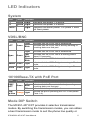
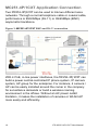
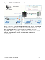
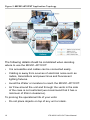
1
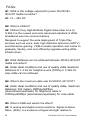
IFS MC251-4P/1CXT User Manual P/N 1072578 • REV 00.05 • ISS 30JAN13 Copyright Trademarks and patents Intended use Manufacturer © 2013 UTC Fire & Security Americas Corporation, Inc. Interlogix is part of UTC Climate Controls & Security, a unit of United Technologies Corporation. All rights reserved. The IFS MC251-4P/1CXT and logo are trademarks of United Technologies. Other trade names used in this document may be trademarks or registered trademarks of the manufacturers or vendors of the respective products. Use this product only for the purpose it was designed for; refer to the data sheet and user documentation for details. For the latest product information, contact your local supplier or visit us online at www.interlogix.com. UTC Fire & Security Americas Corporation, Inc. 2955 Red Hill Avenue Costa Mesa, CA 92626-5923, USA EU authorized manufacturing representative: UTC Fire & Security B.V., Kelvinstraat 7, 6003 DH Weert, The Netherlands Certification FCC compliance ACMA compliance Canada European Union directives Contact information Contact support N4131 This equipment has been tested and found to comply with the limits for a Class A digital device, pursuant to part 15 of the FCC Rules. These limits are designed to provide reasonable protection against harmful interference when the equipment is operated in a commercial environment. This equipment generates, uses, and can radiate radio frequency energy and, if not installed and used in accordance with the instruction manual, may cause harmful interference to radio communications. You are cautioned that any changes or modifications not expressly approved by the party responsible for compliance could void the user's authority to operate the equipment. Notice! This is a Class A product. In a domestic environment this product may cause radio interference in which case the user may be required to take adequate measures. This Class A digital apparatus complies with Canadian ICES003. Cet appareil numérique de la classe A est conforme á la norme NMB-003du Canada. 2004/108/EC (EMC Directive): Hereby, UTC Fire & Security Americas Corporation, Inc. declares that this device is in compliance with the essential requirements and other relevant provisions of Directive 2004/108/EC. 2002/96/EC (WEEE directive): Products marked with this symbol cannot be disposed of as unsorted municipal waste in the European Union. For proper recycling, return this product to your local supplier upon the purchase of equivalent new equipment, or dispose of it at designated collection points. For more information see: www.recyclethis.info. For contact information see our Web site: www.interlogix.com. www.interlogix.com/customer support Contents Overview 1 Package Contents 1 Ethernet over VDSL2 Bridge Description 1 Key Features 3 Hardware Overview 4 LED Indicators 5 System 5 VDSL/BNC 5 10/100Base-TX with PoE Port 5 Mode DIP Switch 5 Top Panel 7 Installation 8 Installing the MC251-4P/1CXT 8 MC251-4P/1CXT BNC/RJ-11 Connection 9 MC251-4P/1CXT Application Connection 10 Wiring the Power Inputs 13 Wiring the Fault Alarm Contact 14 Mounting Installation 15 Troubleshooting 19 FAQs 20 Specifications 22 Contacting Technical Support 24 IFS MC251-4P/1CXT User Manual i Overview Package Contents Before installing the IFS MC251-4P/1CXT Industrial Ethernet Converter, verify that the package contains the following parts: • MC251-4P/1CXT x1 • DIN Rail Kit x1 • Wall Mount Kit x1 • User’s Manual x1 If any of the items in the package are damaged or missing, please contact your distributor or IFS sales rep. If possible, retain the original carton and packaging material in case of need to return the product for repair/replacement. Ethernet over VDSL2 Bridge Description IFS’s state-of-the-art Ethernet-over-VDSL2 products are based on two core networking technologies: Ethernet and VDSL2 (Very-high-data-rate Digital Subscriber Line 2). This technology offers the absolute fastest possible data transmission speeds over existing copper telephone lines or coaxial cables without the need for rewiring. The IFS MC251-4P/1CXT PoE Industrial Ethernet Converter has a switching architecture with 4 PoE RJ-45 10/100Mbps Ethernet ports and one asymmetric or symmetric Ethernet over VDSL port (Asymmetric means upstream and downstream rate are not the same and Symmetric means upstream and downstream rate are similar) – the VDSL port can be RJ-11or BNC Connector. The MC251-4P/1CXT can be set to Master or Slave mode via a DIP switch. The MC251-4P/1CXT (RJ-11) is connected with IFS MC251-4P/1CXT User Manual 1 another MC251-4P/1CXT device, the performance is up to 99/63Mbps for asymmetric data rate within 200m and up to 28/2Mbps at 1.4km. The MC251-4P/1CXT (BNC) performance is up to 99/65Mbps for asymmetric data rate within 200m and up to 31/4Mbps at 2.4km. This capability is ideal for use as an Ethernet extender for your existing Ethernet network. With 4 PoE interfaces, the MC251-4P/1CXT is the ideal for small business and workgroups requiring to deploy PoE for the wireless access points, IP-based surveillance camera or IP phones in any places easily, efficiently and cost effective. The IFS MC251-4P/1CXT Industrial Ethernet Converter is engineered in a slim metal enclosure that conforms to IP30 standards for deployment in demanding industrial environments. The IFS MC251-4P/1CXT provides a lower cost replacement and smooth migration for existing Long Reach Ethernet (LRE) networks. The cable specifications of the connection are listed as following: • 10Base-T, Category 3, 4 or 5 UTP • 100Base-TX, Category 5, 5e or 6 UTP • Ethernet over VDSL2, Twisted-pair Telephone Wires • Ethernet over VDSL2 Coaxial Cable Note: Slave devices (CPE) must connect to the Master device (CO) through the telephone wire or coaxial cable. To define the MC251-4P/1CXT as a Master or Slave, please refer to the Mode DIP Switch section for more detail. 2 IFS MC251-4P/1CXT User Manual Key Features The MC251-4P/1CXT provides the following key features: • • • • • 4 x Ports IEEE 802.3af Power over Ethernet Standard Each of PoE port provides 15.4 Watts Cost-effective VDSL2 Master / Slave bridge solution via DIP Switch Selectable BNC and RJ-11 mode for the data transmission -40 to 75 Degree C operating temperature Redundant Power Design: 24V or 48V DC, redundant power with polarity reverse protect function IP30 Aluminum metal case Protection Defines Asymmetric (Band Plan 998) and Symmetric band plans for the transmission of Upstream and Downstream signals Complies with IEEE 802.3, IEEE 802.3u and IEEE 802.3x standards DMT (Discrete Multi-Tone) line coding Half Duplex Back Pressure and IEEE 802.3x Full Duplex Pause Frame Flow Control Support up to 1536 bytes packet size, 802.1Q VLAN tag transparent Integrated address look-up engine, support 2K absolute MAC addresses VDSL2 Stand-Alone transceiver for simple bridge modem application Selectable Target Band Plan and Target SNR Margin LED indicators for network diagnostics • DIN Rail and Wall Mount Design • • • • • • • • • • • IFS MC251-4P/1CXT User Manual 3 Hardware Overview The MC251-4P/1CXT provides 4 RJ-45 with PoE, 1 RJ-11 and 1 BNC port for network line connection. The 4 RJ-45 ports with two different data rates – 10Mbps and 100Mbps. The MC251-4P/1CXT will distinguish the speed of the incoming data automatically. This section describes the hardware features of the PoE Industrial Media Converter. For easier control of the MC2514P/1CXT, familiarity with its display indicators and ports. Front panel illustrations in this chapter display the unit LED indicators is important. Before connecting any network device to the MC251-4P/1CXT, read this chapter carefully. Figure 1: Front Panel 4 IFS MC251-4P/1CXT User Manual LED Indicators System LED P1 P2 FAULT Color Function Green Light Green Light Green Light Indicates that power 1 is active. indicates that power 2 is active. indicates that either power 1 or power 2 does not have power. VDSL/BNC LED Color ACT Green Sync Green Function Light Indicates that the VDSL link is established. Indicates that the VDSL link is actively sending or Blink receiving data over that port. Light Indicates that the VDSL link is established. Fast Blink Slow Blink Indicates that the VDSL link is at training status (about 10 seconds). Indicates that the VDSL link is at idle status. Master Green Light Slave Light Green Indicates that the VDSL Bridge is running in Master mode. Indicates that the VDSL Bridge is running in Slave mode. 10/100Base-TX with PoE Port LED Color Function Light Indicates that the port is link up. LNK/ Indicates that the Converter is actively sending or Green Blink receiving data over that port. ACT Off Indicates that the port is link down. PoE Indicate the port is providing 48V DC in-line power. Orange Light (Ports 1-4). in-Use Mode DIP Switch The MC251-4P/1CXT provides 4 selective transmission modes. By switching the transmission modes, you can obtain a best transmission mode to suit the phone line quality or IFS MC251-4P/1CXT User Manual 5 distance of connectivity. The following is a summary table of transmission settings, bandwidth and distance extensibility tested for AWG 24 (0.5mm) twisted-pair without noise and cross talk. DIP-1 DIP-2 DIP-3 DIP-4 Mode Channel Band Plan SNR OFF Master Interleave Symm 9dB ON (default) Slave Fast Asymm 6dB Master / Slave • Master (Central Office) – in Master device mode, usually the Master device will be located at the data center of the ISP or enterprise to link to the backbone. For IP video applications, the Master (CO) setting should be used at the IP camera for maximum bandwidth availability over distance. • Slave (Customer Premises Equipment) – the Slave device mode, usually the Slave device will be located at thre branch office, home or remote side as the long reach data receiver. The Slave can also be connected to the network devices such as a PC, VoIP, Wireless Access Point, etc. When the MC251-4P/1CXT is operating in Slave mode, the DIP switch 2, 3, and 4 are disabled. Link Type • BNC mode allows the MC251-4P/1CXT to connect and data transfer by using BNC cable 6 IFS MC251-4P/1CXT User Manual • RJ-11 mode allows the MC251-4P/1CXT to connect and data transfer by using Telephone Wire Band Plan • User can switch the Band Plan to either Symmetric or Asymmetric based on the application. Symmetric band plan provides better upstream performance while Asymmetric band plan provides a better downstream performance. Target SNR (Signal Noise Ratio) Margin • When fixed SNR margin is selected, the system will maintain the SNR margin at 9 dB across all usable loop length. Note: The default for the DIP switch settings is "ON" for all four switches, that sets the media converter to CPE mode. For selecting "CO" mode, please adjust the DIP 1 switch to "OFF". Please power off the MC251-4P/1CXT before making any transmission mode adjustments. Top Panel The top panel of the MC251-4P/1CXT consists of a terminal block connector with two DC power inputs. Figure 2 shows the top panel of the MC251-4P/1CXT. IFS MC251-4P/1CXT User Manual 7 Figure 2: Top Panel Installation Installing the MC251-4P/1CXT The MC251-4P/1CXT does not require any software configuration. Users can immediately use any features of this product simply by attaching the cables and power plug. There are some key limitations on the MC251-4P/1CXT. Please check the following items: MC251-4P/1CXT: The device is used for Point-to-Point connection only (Master device to Slave device) and is equipped with one RJ-11 and one BNC connectors for VDSL2 port for network link connection. Phone wire: Depending on the quality of the telephone line being used, the maximum distance of one VDSL segment is 1.6km (5249ft) with AWG 24 telephone wires. Coaxial: Depending on the quality of the coaxial cable being used, the maximum distance of one VDSL segment is 3.0km (9842ft) with 50 or 75 ohm coaxial cable. The distance achieved will vary according to the quality of telephone wires and coaxial cables. 8 IFS MC251-4P/1CXT User Manual MC251-4P/1CXT BNC/RJ-11 Connection The IFS MC251-4P/1CXT has a DIP switch which can adjust the unit to be in Master or Slave mode. Connection of two IFS MC251-4P/1CXT units, one must be set to Master (CO) mode and the other must be set to Slave (CPE) mode. Please refer to the following figure. IFS MC251-4P/1CXT User Manual 9 MC251-4P/1CXT Application Connection Two MC251-4P/1CXT can be used to link two different area networks. Through a normal telephone cable or coaxial cable, performance is 99/63Mbps (RJ-11) or 99/65Mbps (BNC) asymmetric backbone. Figure 3: MC251-4P/1CXT BNC and RJ-11 connection With 4 PoE, in-line power interfaces, the MC251-4P/1CXT can build a power central-controlled IP phone system, IP camera system, AP group for the enterprise. For instance, 4 camera / AP can be easily installed around the corner in the company for surveillance demands or build a wireless roaming environment in the offices. Without an AC power outlet limitation, it makes the installation of cameras or WLAN AP more easily and efficiently. 10 IFS MC251-4P/1CXT User Manual Figure 4: MC251-4P/1CXT PoE connection MC251-4P/1CXT temperature range is from -40 to 75 Degree C which can handle any harsh environment and places. It is also compatible with IFS MCR200-1T/1CX and MC2504T/1CXT. Without spending extra cost to deploy a new local Internet in apartment, hotel, campus and hospitality environment. IFS MC251-4P/1CXT User Manual 11 Figure 5: MC251-4P/1CXT Application Topology The following details should be considered when deciding where to use the MC251-4P/1CXT: • It is accessible and cables can be connected easily. • Cabling is away from sources of electrical noise such as radios, transmitters and power lines and fluorescent lighting fixtures. • Avoid the Water or moisture to reach the MC251-4P/1CXT. • Air Flow around the unit and through the vents in the side of the case is not restricted (we recommend that it has a minimum of 25mm clearance). To prolong the operational life of your units: • 12 Do not place objects on top of any unit or stack. IFS MC251-4P/1CXT User Manual Wiring the Power Inputs The 6-contact terminal block connector on the top panel of the MC251-4P/1CXT is used for two DC redundant power inputs. Please follow the steps below to insert the power wires. 1. Insert positive / negative DC power wires into the contacts 1 and 2 for POWER 1, or 5 and 6 for POWER 2. V1- V1+ V2- V2+ 2. Tighten the wire-clamp screws to prevent the wires from disconnecting. 1 - 2 Power 1 + IFS MC251-4P/1CXT User Manual 3 4 5 Fault 6 Power 2 - + 13 Wiring the Fault Alarm Contact The fault alarm contacts are in the middle of the terminal block connector as the picture shows below. Inserting the wires, the MC251-4P/1CXT will detect the fault status of the power failure and then forms an open circuit. The following illustration shows an application example for wiring the fault alarm contacts. 1 2 3 4 5 6 Insert the wires into the fault alarm contacts Note: The wire gauge for the terminal block should be in the range between 12 ~ 24 AWG. The alarm relay circuit accepts up to 30V, max. 3A currents. 14 IFS MC251-4P/1CXT User Manual Mounting Installation This section describes how to mount the MC251-4P/1CXT and make connections to it. Please read the following sections and perform the procedures in the order presented. Note: In the installation steps below, this Manual uses the IFS GE-DSGH-8 8 Port Industrial Gigabit Switch as an example. However, the steps for any IFS Industrial Switch & Industrial Media Converters are similar. Mounting to a DIN-Rail The DIN-Rail kit comes assembled on the MC251-4P/1CXT out of the box. Please refer to following figures to hang the MC251-4P/1CXT on a DIN-Rail. 1. Lightly press down and push the bottom of the DIN-Rail connector mount into the track. IFS MC251-4P/1CXT User Manual 15 2. Check that the DIN-Rail connector mount is tightly mounted on the track. 3. Please refer to following procedures to remove the MC2514P/1CXT from the track. 16 IFS MC251-4P/1CXT User Manual 4. Lightly press down and pull the bottom of the DIN-Rail connector mount to remove it from the track. Mounting to a Wall To install the MC251-4P/1CXT on the wall, please follows the instructions described below. 1. Loosen the screws to remove the DIN Rail from the Media Converter. 2. Place the wall mount plate on the rear panel of the MC2514P/1CXT. IFS MC251-4P/1CXT User Manual 17 3. Assemble the wall mount plate on the MC251-4P/1CXT. 4. Use the hook holes at the corners of the wall mount plate to hang the MC251-4P/1CXT on the wall. 18 IFS MC251-4P/1CXT User Manual Troubleshooting SYMPTOM: VDSL LNK LED does not light after wire is connected to the VDSL port. CHECKPOINT: • Verify that the length of the wire connected between two MC251-4P/1CXT is not more than 2.4km. Please also try to adjust the DIP switch of the MC251-4P/1CXT to other SNR mode. • Please note you must use one MC251-4P/1CXT with Master mode and the other MC251-4P/1CXT with Slave mode. SYMPTOM: TP LED does not illuminate after the cable is connected to the port. CHECKPOINT: • Verify that you are using the Cat. 5, 5e or 6 cables with an RJ-45 connector to connect to the port. • If your device (i.e. LAN card) supports Auto-Negotiation, try to set it to a fixed speed manually. • Make sure that both converter and the connected devices are turned on. • Make sure that all cables are properly plugged into the correct ports. • Make sure that the cable is not bad. • Make sure that the power adapters are functional for each device. IFS MC251-4P/1CXT User Manual 19 FAQs Q1: What is the voltage required to power the MC2514P/1CXT media converter? A1: 12 ~ 48V DC Q2: What is VDSL2? A2: VDSL2 (Very High-Bit-Rate Digital Subscriber Line 2), G.993.2 is the newest and most advanced standard of xDSL broadband wire line communications. Designed to support the wide deployment of Triple Play services such as voice, data, high definition television (HDTV) and interactive gaming, VDSL2 enable operators and carrier to gradually, flexibly, and cost efficiently upgrade exiting xDSLinfrastructure. Q3: What distances can be achieved between MC251-4P/1CXT media converters? A3: Under ideal conditions and use of quality cable maximum distances of 1.4 km for telephone wire (POTS) or 2.4km for coax cable can be achieved. Q4: What is the maximum date rate for MC251-4P/1CXT? A4: Under ideal conditions and use of quality cable, maximum distances: 200 meters, 99Mbps/63Mbps (downstream/upstream) for telephone cable or 100Mbps/65Mbps (downstream/upstream) for coax cable. Q5: What is SNR and what’s the effect? A5: In analog and digital communications, Signal-to-Noise Ratio, (SNR), is a measure of signal strength relative to 20 IFS MC251-4P/1CXT User Manual background noise. The ratio is usually measured in decibels (dB). In digital communications, the SNR will probably cause a reduction in data speed because of frequent errors that require the source (transmitting) computer or terminal to resend some packets of data. SNR measures the quality of a transmission channel over a network channel. The greater the ratio, the easier it is to identify and subsequently isolate and eliminate the source of noise. Generally speaking, the higher SNR value gets better line quality, but lower performance. Q6: What is band plan and what’s the effect? A6: VDSL2 defines multiple band plans and configuration modes (profiles) to allow asymmetric and symmetric services in the same binder (by designated frequency bands) for the transmission of upstream and downstream signals. User has the ability to select fixed band plan. Symmetric band plan provides better downstream performance while Asymmetric band plan provides better upstream performance. IFS MC251-4P/1CXT User Manual 21 Specifications Product MC251-4P/1CXT Hardware Specification 10/100 Base-TX Ports PoE VDSL DIP Switch 4 x RJ-45, Auto-Negotiation and Auto-MDI/MDI-X 4 x PoE (Port1 ~ Port4) 1 x RJ-11, female Phone Jack 1 x BNC, female connector 4 position DIP switch Master / Slave mode select Selectable BNC and RJ-11 mode Functionality*1 Selectable target Band Plan Selectable target SNR mode VDSL-DMT - ITU-T G.997.1 - ITU-T G.993.1 VDSL - ITU-T G.993.2 VDSL2 (Profile 17a Support) Encoding P1 (Green) P2 (Green) Fault (Green) LED Indicators Master (Green) and Slave (Green) ACT (Green) Sync. (Green) PoE ( Orange) Power Over Ethernet PoE Standard IEEE 802.3af Power over Ethernet / PSE PoE Type End-Span PoE Power Input 24V or 48V DC power input source PoE Power Output 48V DC Per Port, 350mA . Max. 15.4 Watts PoE Pin Assignment Cabling 1/2(+), 3/6(-) Ethernet VDSL(RJ-11) Twisted-pair telephone wires (AWG24 or better) up to 1.4km BNC 50 ohm: RG58A/U, RG58C/U, RG58/U and 75 ohm: RG6 (Distance 2.4km) 10Base-T: 2-pair UTP Cat.3,4,5 up to 100m (328ft) 100Base-TX: 2-pair UTP Cat.5, 5e, 6 up to 100m (328ft) Asymmetric Mode VDSL (RJ-11) 22 BNC IFS MC251-4P/1CXT User Manual Performance*2 (Down Stream / Up Stream) 200m -> 99/65Mbps 400m -> 99/64Mbps 600m -> 97/59Mbps 800m -> 94/51Mbps 1000m -> 84/45Mbps 1200m -> 73/37Mbps 1400m -> 61/28Mbps 1600m -> 54/20Mbps 1800m -> 48/13Mbps 2000m -> 39/9Mbps 2200m -> 35/6Mbps 2400m -> 31/4Mbps 200m -> 99/63Mbps 400m -> 91/48Mbps 600m -> 71/32Mbps 800m -> 53/18Mbps 1000m -> 38/8Mbps 1200m -> 33/5Mbps 1400m -> 28/2Mbps Symmetric Mode VDSL (RJ-11) 200m -> 91/99Mbps 400m -> 74/79Mbps 600m -> 54/51Mbps 800m -> 38/34Mbps 1000m -> 27/21Mbps 1200m -> 24/15Mbps 1400m -> 21/10Mbps BNC 200m -> 95/99Mbps 400m -> 92/97Mbps 600m -> 81/82Mbps 800m -> 71/70Mbps 1000m -> 60/57Mbps 1200m -> 50/44Mbps 1400m -> 42/33Mbps 1600m -> 37/27Mbps 1800m -> 29/22Mbps 2000m -> 23/21Mbps 2200m -> 19/17Mbps 2400m -> 19/13Mbps Dimensions (H x W x D) 135mm x 87.8mm x50mm Weight 631g 24V or 48V DC for PoE Devices Redundant power with polarity reverse protection function Power Requirement Power Consumption / Dissipation 66.4 Watts / 226BTU Max. (PoE) 5.64 Watts / 19.24BTU (Non-PoE) Installation Standard Conformance DIN Rail Kit and Wall Mount Ear Operating Temperature IEC60068-2-32(Free Fall) IEC60068-2-27(Shock) IEC60068-2-6(Vibration) -40 ~ 75ºC Storage Temperature -40 ~ 85ºC Operating Humidity 10% to 90%, relative humidity, non-condensing Storage Humidity 10% to 90%, relative humidity, non-condensing Regulation Compliance FCC Part 15 Class A, CE Stability testing IEEE 802.3 10Base-T IEEE 802.3u 100Base-TX IEEE 802.3af Power over Ethernet IEEE 802.3x Full Duplex Pause frame Flow Control Standards Compliance ITU-T 。 G.997.1 。 G.993.1 VDSL 。 G.993.2 VDSL2 (Profile 17a) *1 BNC and RJ-11 mode must be switched to the same position for Master and Slave. Otherwise, it may cause instability. *2. The actual data rate will vary on the quality of the copper wire and environment factors. IFS MC251-4P/1CXT User Manual 23 Contacting Technical Support Contact technical support if you encounter any difficulties during this installation. Please make sure you have the requested diagnostic or log files ready before you contact us by phone or go to www.interlogix.com/customer-support. Technical Support Europe, Middle East and Africa W Select Contact Us at www.utcfssecurityproducts.eu North America T +1 855.286.8889 E [email protected] Australia E 24 [email protected] IFS MC251-4P/1CXT User Manual