1
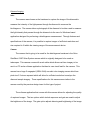
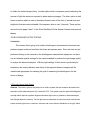
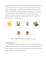
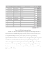
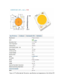
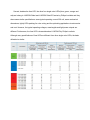
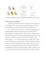
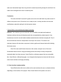
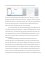
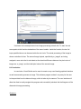
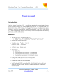
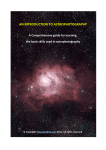
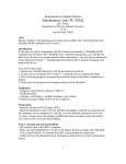
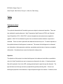
ECE 480 | Design Team 12 Adam Tayloe, Dan Schulz, Chunyu Li, Allen Lin, Dan Kuang Abstract Content Birefringence Physics Intro The synthetic diamonds that Fraunhofer grows are subject to stress and impurities. There are two methods for growing diamond. High Temperature High Pressure (HTHP) and Chemical Vapor Deposition (CVD). With HTHP, extreme temperatures and pressures are applied to graphite. With CVD, the diamond is grown from a chemical reaction between a vapor and a substrate. There is a seed crystal with new diamond formed on top of it. To detect impurities in the synthetic diamond, birefringence is measured. The causes for birefringence in a diamond are: dislocations, lattice parameter variations, precipitates and inclusions, fractures, and plastic deformation. Sometimes these cause the diamond to change color. Objective The objective of this project is to detect birefringence in the diamond, and define a quantitative value for it that Fruanhofer can use to compare one diamond to the other. A linearly polarized filter will be placed in front of an LED, causing polarized light to pass through the diamond. The light will then travel through a second, perpendicularly placed polarizing filter. If there is no birefringent properties in the diamond, no light will pass through to the camera. If however, there are impurities due to one of the properties described in the introduction, light will pass through the second polarizing filter and into the camera. Issues Many issues arise when dealing with such precise measurements. The alignment of the diamond and polarizers must be perfect. If there is any slant or misalignment, the birefringence calculations will be useless. The LED must also produce light with a surface area at least the size of the diamond, or there will be areas that lack a measurement. Ambient light from outside of the system must also be kept to a minimum, insured by the outer shell. Results TO BE CONTINUED AFTER MEASUREMENTS Conclusion There are various reasons that a diamond may express birefringent properties. Fraunhofer is interested in finding a quantitative measure for the birefringence, and being able to identify exactly where in the diamond the stresses and impurities are located. Predicted issues that may arise include proper alignment of the system, and keeping out ambient light from the measurements. References Lang, A. R. "Causes of Birefringence in Diamond." Nature.com. Nature Publishing Group, n.d. Web. 27 Mar. 2014. Diamond Imaging Intro The camera was chosen as the hardware to capture the image of the diamond to measure the intensity of the light passes through the diamond to measure the birefringence. The camera takes a photograph of the diamond to be later used to measure the light intensity that passes through the diamond via the use of a Windows based application designed for performing a birefringence measurement. Through features and specifications of the camera, it is possible to capture images of sufficient resolution and size required to fit within the viewing range of the measurement device. Camera The camera that is going to be used for the birefringence hardware is the Orion StarShoot 5 MP Solar System camera which is originally designed to be used on telescopes. This camera comes with a usb cable which allows real time imagery to be sent to a PC and a software application that has its own visual feed for the camera. This camera has a huge 5 megapixel (2592x1944) oneshot color imaging sensor which has pixel size 2.2 micron squared which will allow for sufficient resolution to analyze the diamond sample imagery. These specifications for this camera were similar to the camera used by the previous design team for this type of project. The software application that comes with this camera allows for adjusting the quality of captured images. The two options which include exposure and gain are used to adjust the brightness of the image. The gain option adjusts dimming and brightening of the image to obtain the desired image clarity. Another option which is exposure permits adjusting the amount of light the camera is exposed to when capturing images. The other option is dark frame correction which is used to eliminate inherent noise in the form of vertical lines and bright dots that becomes noticeable if the exposure time is over 3 seconds. These options can be found in page 6 and 7 of the Orion StarShoot 5 Solar System Camera user manual. Issues TO BE CONTINUED AFTER TESTING Conclusion The camera that is going to be used in birefringence measurement instrument can produce images in desired resolution that team and sponsor want. Since we have not yet performed testing on the camera for the birefringence measurement equipment, we have not yet obtained optimal settings for the camera needed to produce the right image quality to analyze the diamond samples. With the right settings for this camera, particularly for brightness, the viewing distance and clarity of the captured diamond samples will be useable and appropriate for reaching the goal of measuring the birefringence for this choice of design. 4 The Light Source SubSystem Abstract: The team’s goal for this project is to build a system that can measure and detect the impurities of the diamonds grown by Fraunhofer CCL. The system uses the optical birefringence concept which requires a perfect alignment between light source, polarizers, diamond sample, and the light detector (camera). For the light source subsystem, the previous team used a laser pointer as their light source. However, the laser had a nonuniform distribution of its light, which created spots on the diamond. The current team chose Light Emitting Diodes (LED) as new light source. Compared to the laser, LEDs can generate the same amount of power, but with more uniform and crisp light beams. To obtain and calculate multiple measurements, the team chose six different colors of LEDs, each emitting light at different wavelengths (white, blue, lime, green, orange and red). Finally, to integrate these LEDs into one light source system, a voltage regulator is required that provides different voltages for each LED. Eventually, a knob switch might be needed to turn on a single output LED. Figure 41 Multiple LEDs that were utilized in light source system 4.1 LEDs Implementation The LEDs can be categorized into two types, one is high power white LED and the other is high power single color LED. All the LEDs are manufactured by Philips Lumileds and sold by Mouser. Additionally, each LED is characterized as high power LED which can generate enough power for researching in some scientific experiments. Figure 42 LEDs Part Numbers and Costs First, the white LED has notable difference comparing to the other single color LEDs. It was characterized as LUXEON CoB by Philips Lumileds, which are available in 3Step as well as 5Step MacAdam Ellipse, enabling uniform optical performance in general lighting applications. The benefits of this white LED are various; it has higher efficiency that can generate over 130 lumens per watts at 35.5 volts, takes less space (refer to the figure below), more uniform and crisp light beams that the typical total included angle (Total angle at which 90% of total luminous flux is captured) is 125 degree and the typical viewing angle (the off axis angle from lamp centerline where the luminous intensity is half of the peak value) is around 100 degree (High Power LEDs White). Figure 43 The Mechanical Dimension, specifications and appearance of the White LED Second, besides the lime LED, the other four single color LEDs (blue, green, orange and red) are belong to LUXEON Rebel and LUXEON Rebel ES series by Philips Lumileds and they share some similar specifications: same typical operating current 350 mA, same mechanical dimensions, tightly LEDs packing for color mixing and the optimizing applications to reduce size and cost. However, the typical operating voltages, wavelengths and light power outputs are different. Furthermore, the lime LED is characterized as LUXEON Z by Philips Lumileds. Although many specifications of lime LED are different from other single color LEDs, the basic utilization is similar. Figure 44 The Mechanical Dimension, specifications and appearance of the Color LEDs 4.2 Voltage Regulator Implementation Corresponding to the two types of LEDs, the voltage regulator can be designed by two plans. First design is for the single color LEDs, which provides the voltage from 2.1 volts to 3 volts. The other design is for the white LED, which offers the voltage around 36 volts. First, for the single color LED, a Wall Wart (9 V, 300 mA) and voltage regulators such as LM2940 and LM3940 are selected to build the power supply for single color LEDs. The schematic diagram is in the bottom of this page. The spot 4 is the output voltage of the power supply. However, the voltage is higher than the typical voltages of single color LEDs, so a simple resistors circuit in series can solve this problem. Using red LED for example, the typical operating voltage is 2.1 volts. To obtain this particular voltage, connecting a 10 ohms (actual value is 10.296 ohms) and an 18 ohms (actual value is 18.334 ohms) resistor in series that one side connect to the 3.3volts (measuring the actual output voltage is 3.282 volts). Eventually, connecting the red LED parallel with the 18 ohms resistor. The voltage of the LED would be 3.282*[18.334/(18.334+10.296)] = 2.1003 volts. By changing the resistor combinations, the other single color LEDs can be operated by this voltage regulator system. The theory to operate the White LED is similar to operate single color LEDs but might need a different wall wart (36 volts) and LM voltage regulators. Figure 45 Voltage Regulator Circuit Schematic Diagram for Single Color LEDs 4.3 Conclusion Above all, after measuring all the spectrum of the LEDs and testing all the LEDs with the camera, the team would select the best LED for the final birefringence detection system. The White LED has the greatest potential because of its largest optical power output. Then, the corresponding final voltage regulator design would also be determined. References "High Power LEDs White Cool White, 5000K 80CRI." Mouser Electronics. Mouser, n.d. Web. 26 Mar. 2014. "High Power LEDs – Single Color." Philips Lumileds. Philips, n.d. Web. 26 Mar. 2014. Stephen A. Zajac & Gregory M. Wierzba. “ECE 480L: SENIOR DESIGN SCHEDULED LAB”. Lab handbook. Michigan State University. East Lansing. Spring 2014. Outer Shell Intro The outer shell is a very important part of this project because it functions as a shield for the inner circuitry and shields ambient light from getting into the system. If too much ambient light gets into the system then the measurements become inaccurate. Also it is desirable for the outer shell to be robust, this way in case any unforeseen accident happens the measurement system will not break. Design The way this was done was through a 3dimensional printing software known as NX. The measurements for the outer shell were in part done to try and make the shell as large as possible so that it would leave extra room for the LED light and the voltage regulator. At the top of the shell is a hole which is designed so that the camera could be placed to take pictures. Below that are three slots for slides. The middle slide is for the diamond sample and the other two slides are for the polarizers. There is also a sliding door which is designed so that it could be removed. That ability to remove the door is important because it is the only way to place slides in the measurement system itself. The outer shell was designed so large that it must be turned sideways on the 3dimensional printing machine (makerbot) in order to fit. Another design consideration is the distance between the polarizers, diamond sample to the camera. It is desirable to place the polarizers and diamond samples as close to the camera as possible because this way less light gets in between the polarizers producing inaccurate results. For the same reason that light could get in between the two filters, it is also important to consider the distance between the polarizers and the sliding door. Minimizing the distance between the polarizers and the sliding door reduces the amount of ambient and LED light that would get in between the polarizers. Another concern regarding the light is whether or not ambient light would get into the system. Therefore it is important that the entire system is surrounded by the outer shell as much as possible even though there is an opening with the sliding door. To mitigate this problem, the sliding door is designed such that the edges of shell and door are angled non perpendicularly. This way it is harder for ambient light to slip through the cracks. Figure 51 shows the design of the outer shell in the NX file and Figure 52 shows the design of the sliding door. Figure 51 Outer Shell Design in NX Figure 51 Outer Shell Sliding Door Design in NX 3D Printing The 3dimensional printing is used to create the outer shell. This printing is done in the DECS lab located in the engineering building on Michigan State University’s campus. In order to do the printing, the files done in NX must be saved as an STL file. At first when the file is opened up, the software on the DECS computer which is responsible for the printing says that physical object itself is too large. This happens because the outer shell is so large that it does not fit in the 3dimensional printing machine when it is sitting upright. In order to make the outer shell fit it must be placed sideways onto the printing platform. 3dimension printing gives the option of choosing which color to use when printing. The color black was chosen for a few reasons. First, black absorbs light more so than other colors. This is important because this way less light gets reflected so less light gets in between the polarizers making the results less accurate. The second reason is that it is harder for light to get through the shell since black is the best color for blocking out the light. This way a greater percentage of the ambient light will be a shielded from the camera. This method of 3dimensional printing uses a type of inexpensive plastic to print. This means that the material is not very robust not very high quality. To ensure robustness and to make sure that ambient light does not get into the camera by traveling through the shell itself, the walls must be designed such that it is relatively thick Conclusion The outer shell itself is around 10 grams and so the outer shell itself only costs around 10 dollars at this point in time. Given that it is so cheap to print, it is likely that there will be some modifications made after testing for the final product starts. 6 Visual Studio: User Interface and Image Processing Abstract: User interfaces give nontechnical users the ability to navigate and implement hardware solutions that would otherwise need to be accomplished by subject experts. User interfaces are crucial in a world where hardware and electronics dominate everyday life. One of the most dominant electronic components nowadays is the sensor. The sensor is so dominant, because this electronic component is able to gather and interpret data while imitating the human sense. One of the most useful kinds of sensors is the camera, as sight is one of the most fundamental human senses. Image processing provides the ability to trivially interpret and manipulate data from these sensors. Visual Studio is a software program that can accomplish this. Visual Studio, a Microsoft program, is an integrated development environment that focuses around user interface and image processing. 6.1 User Interface Implementation Visual Studio allows the user to either build a user interface with one or multiple windows, depending on the intention of the project. When Visual Studio is first opened, the user is prompted to select the programming language that will be used in the development settings. Once the language is selected, the user is brought to the main menu. In order to start a new project; select ‘File’>’New’>’Project’. A new screen will popup and ask what kind of project is to be created. Select ‘MFC Application’ and click ‘Ok’. Once again, a new dialog box will be displayed. Select ‘Application Type’ in the left column of menu options, select the ‘MFC standard’ radio button under ‘Project Style’ and then click ‘Finish’. A new project with multiple windows will be created with precreated classes as shown below. In the next section, I will explain how the user interface can be modified and how to implement the functionality in the code. 6.2 User Interface Modification and Functionality In order to modify the user interface, the user must be in the ‘Resource View’. In order to accomplish this, select ‘View’>’Resource View’ from the main menu. Next, singleclick on the ‘MFCApplication1’ arrow in the left column ‘Resource View’ tab. Repeat this step for ‘MFCApplication1.rc’ and ‘Menu’. Finally, doubleclick on the option ‘IDR_MFCApplication1TYPE’. The menu that will be displayed when the program is run is shown as seen below. As seen above, new menu options can be added by typing in the “Type Here…” box. Other functionality can be added, such as buttons text boxes, etc., through the ‘Toolbox’ tab, which is specified by the red arrow. To use the tools contained in the ‘Toolbox’ tab, simply draganddrop the tool to be used onto the screen. The left column options, as specified by the blue circle, allows for the creation of dialogue boxes, tables, icons, and toolbars. In order to implement the menu option functionality as part of the code, right click on the menu option to add, select ‘Add Event Handler…’ and select ‘CMFCApplication1Doc’ under the class list and click ‘Ok’. This process will create a function for the selected menu option, which can be manipulated in the code, under the ‘MFCApplication1Doc.cpp’ class option. In order to return to the list of available classes, simply click the ‘Class View’ tab in the lower lefthand corner of the screen. In order to implement dialog boxes, an important aspect when it comes to user interfacing, rightclick on the main ‘MFCApplication1’ tab up at the top of the ‘Resource View’. Next, select ‘Add’>’Resource’. When a new box is displayed, select ‘Dialog’ and click ‘New’. To add functionality to the newlycreated dialog box, draganddrop the appropriate tools from the toolbox. When the dialog box is up to user standard, rightclick on the dialog options that takes user input and select ‘Add Variable’. This creates a variable that is associated with the input of the user. In order to connect the actual dialog box to the code, rightclick on the dialog box and select ‘Add Class’. Give the dialog a class name such as ‘CDialog’. The functionality of the dialog box will be associated with the newlycreated class and the menu handlers. 6.3 Image Processing In Visual Studio, only .bmp and .jpeg formats are acceptable for processing. In addition the program and file format only support RGB color images. All processing is done internally on 8 bit per pixel RGB data. However, in Visual Studio, the actual data order is BGR (blue, green, and then red). To implement image processing in Visual Studio, there is a special class in the library called ‘CGrImage.h’ and ‘CGrImage.cpp’. These files must be included by placing ‘#include graphics/GrImage.h’ at the top of the appropriate classes. This header and source file contain certain functions that help with image processing. These functions include GetWidth() and GetHeight(), which return the number of pixels in the width and height of the picture, respectively. Another useful function is LoadFile(), which loads an acceptable file into the specified variable. Finally, the function SetSameSize(variable) function allows the calling variable to be set as the same pixel size as the variable in the parameters. In order to properly use these functions, a variable of type ‘CGrImage’ must be created and then call these functions as methods. To perform image processing, the user must load in an acceptable image and save it to a variable of type CGrImage, using the LoadFile() function. Two ‘for’ loops, one to iterate the width of the picture and one to iterate the height of the picture, need to be created in order to traverse every pixel of the image. This image processing must be implemented in the menu handler function that was created during the modification of the user interface. See the figure below in order to have a better understanding of the implementation of image processing in code. It’s shown in the example above how image processing is dealt with. To start, the red arrow points to the function declaration of the menu handler. Inside the function, the two ‘for’ loops specified above can be seen inside the red circle. The actual processing of the image is shown underlined in blue. The second image’s pixels, specified by m_image2, are being assigned a new value that is calculated as the absolute difference between the pixel value of image one, m_imag1, and the initial pixel value of the second image. 6.4 Conclusion In conclusion, Visual Studio can be used to create a very userfriendly graphical interface as well as accurately process an image. This software program makes it very easy for the user to interpret data from the diamond image, which is taken by the camera. The user interface will allow the client to easily navigate the program and successfully calculate the birefringence of the diamond via image processing. Summary Content Bibliography Content