1
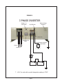
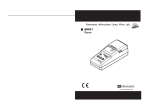
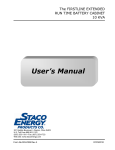
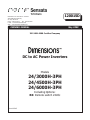
120015D
Manufacturer of DimensionsTM Inverters
4467 White Bear Parkway
St. Paul, MN 55110
Phone: 651-653-7000
Fax: 651-653-7600
E-mail: [email protected]
Web: www.dimensions.sensata.com
OWNERS MANUAL
May 2009
ISO 9001:2000 Certified Company
DC to AC Power Inverters
Models
24/3000H-3PH
24/4500H-3PH
24/6000H-3PH
Including Options:
R6: Remote switch 24Vdc
Form 120015
CAUTION: The inverter contains a circuit
breaker and capacitor that may produce a
spark. Do not mount in a confined battery
or gas compartment.
CAUTION: Working in the vicinity of leadacid battries is dangerous. Batteries generate explosive gases during operation. There
is a risk of acid exposure. There is also a
risk of high current discharge from shorting
the battery that can cause fire and explosion.
CAUTION: Be sure the inverter is turned
"OFF" during installation.
OWNERS MANUAL
FOR SENSATA TECHNOLOGIES
INVERTER MODELS
24/3000H-3PH
24/4500H-3PH
24/6000H-3PH
Table of Contents
1.
2.
3.
4.
5.
6.
7.
Page
General . . . . . . . . . . . 2
Description . . . . . . . . 2
Installation . . . . . . . . 2
Start Up/Operation. . . 4
Troubleshooting. . . . . 4
Installation Figure 1. .
5
Limited Warranty . . . . 6
1. GENERAL
1.01 Dimensions inverters have been
designed and manufactured for many user
applications and long life. They utilize patented construction methods and high
technology electronic parts and circuitry.
1.02 The inverter is powered by a 24 volt
auxilary battery. The remote On/Off control
circuitry requires + 12 volts to operate.
1.03 CAUTION: Inverters produce hazardous voltages, to avoid risk of harm or
fire the unit must be properly installed.
There are no user serviceable parts inside,
do not remove the cover.
CAUTION: The inverter should not be
mounted in a location that may be exposed
to rain or spray.
CAUTION: The inverter should not be
installed in a zero clearance enclosure.
CAUTION: Damage to the inverter will
occur if correct polarity is not observed
when installing the DC input cables.
CAUTION: Damage to the inverter will
occur if an external AC power source is
applied to the inverter’s AC output or it’s
hardwire output.
TM
2. DESCRIPTION
2.01 The inverters converts 24VDC to 220
VAC, 3 phase; or 220 VAC single phase; or
120 VAC, single phase; all at 60 HZ, having
a quasi-sine wave form.
2.02 The inverters have internal protection
against output short circuit, output overload
and high temperature conditions. Also,
there are thermally controlled cooling fans.
2.03 The inverters are designed to operate
almost any 60 HZ appliance, equipment or
tool within their voltage, phase and power
ratings that does not require a pure sine
waveform.
3. INSTALLATION
3.01 The following instructions should be
thoroughly read and understood before
installation.
3.02 CAUTION: Inverters produce hazardous voltage, and to avoid risk of harm or
fire the unit must be properly installed.
CAUTION: The inverter should not be
mounted in a location that may be exposed
to rain or spray.
CAUTION: The inverter should not be
installed in a zero clearance enclosure.
CAUTION: When working near batteries,
safety goggles should be worn.
CAUTION: Be sure the inverter is turned
"OFF" during installation.
Page 2
NOTE: All wiring must follow the National
Electric Code, provincial or other codes in
effect at the time of installation, regardless
of suggestions in this manual. All wires
should be copper conductors.
3.03 Mounting
3.03.1 Locate a suitable, secure flat
mounting surface as close to the 24 volt auxilary
batteries as possible without being in the same
air tight compartment. The maximum
recommended distance between the mounting
location and the battery is 10 feet.
3.03.2 The location should provide
adequate ventilation and clearance to
maintain room temperature while the unit is
operating. At least 1/2 inch of clearance is
required on all sides.
3.03.3 Secure the unit with 1/4" screws
or bolts in the mounting holes on the legs of
the unit.
3.04 Chassis Bonding Lug - FIG.1
3.04.1 Connect a #8 gauge or greater
wire between the bonding lug on the inverter and the system ground or vehicle
chassis.
3.05 DC Wiring - FIG. 1
3.05.1 CAUTION: Assure that hydrogen
gas does not accumulate near the battery
by keeping the area well ventilated. A spark
may result when connecting the final battery wiring due to initial charging of the
internal input capacitor.
3.05.2 Use stranded copper cable
between the battery and the inverter as
indicated. Keep the distance to less than 10
feet. A line fuse must be installed between
the battery and the inverter. UL requires
that the fuse be within 18 inches of the
battery.
Cable gauge Line fuse
24/3000H-3PH
2/0
400 amp
24/4500H-3PH
3/0
500 amp
24/6000H-3PH
4/0
600 amp
Page 3
3.05.3 Use only an approved fuse holder
with a U.L. listed fuse as indicated above.
3.05.4 Using smaller input cable or longer
length will greatly degrade the inverter peak
performance.
IMPORTANT NOTE FOR VEHICLE
INSTALLATION: Do not use the vehicle
chassis as the negative return in place of a
return cable. Use the same size cable as
the positive connection and run directly to
the battery.
3.05.5 Install the cables at the battery,
inverter and then fuse holder. Make sure
that clean, tight connections are made. Use
care not to touch the positive and negative
cables together. A violent spark will result
and could result in exploding batteries and
fire.
3.05.6 The battery input terminals are
located in the wiring compartment. A
mounting spark may result when connecting
the battery wire, due to an initial charging of
the internal input capacitor.
3.05.7 CAUTION: Connecting the
inverter to the wrong polarity of the battery
will cause damage that is not covered under
warranty.
3.06 Remote ON/OFF Switch - FIG. 1
NOTE: The inverter will not switch on
unless the violet wire has +12 VDC applied
to it.
3.06.1 All material used for the remote
switch should be U.L. listed and installed per
low voltage, Class 2, wiring code. The
remote switch hookup can not provide
additional current to operate a indicating
lamp.
3.06.2 The remote switch should be
single pole and have at. least a 5 amp
rating, such as Leviton No. 1330-2. The
wire used should be at least 18 gauge.
3.06.3 The switch should be mounted at
a convenient location in a listed outlet box
with approved strain relief.
3.06.4 The remote switch should be
connected to the violet wire marked “Remote Switch Hookup” in the wiring compartment. Positive (+)12 battery voltage must
be connected to the other side of the
switch. Cable clamp strain relief should be
used to secure the field wires.
3.06.5 Units with a model designation
ending in "R6" have the remote On/Off
switch circuit modified to accept +24 VDC
instead of +12 VDC. The remote switch
must be connected to the violet wire
marked "Remote Switch Hookup".
3.07 220Y/120 VAC Output
3.07.1 CAUTION: Do not connect
another source of AC power directly to the
output of the inverter. This will result in
damage to the inverter that is not covered
under warranty!
3.07.2 The A.C. output is presented at
the A.C. wiring compartment. The 3 phase
outputs are labeled “L1”, “L2”, “L3”. There
is also an A.C. neutral labeled “N” and a
chassis ground labeled “G”.
3.07.3 To obtain 220 VAC, 3 phase
output, a connection must be made to
L1,L2, and L3.
3.07.4 To obtain 220 VAC, single phase
output, a connection should be made to
any two of the hot leads, as L1 and L2, or
L1 and L3, or L2 and L3.
3.07.5 To obtain 120 VAC, single phase
output a connection. should be made to
any one hot lead and to AC neutral “N”; as
L1 and N, or L2 and N, or L3 and N.
3.07.6 Remote AC outlets should be
mounted at a convenient location in a listed
outlet box with approved strain relief, if
used.
4. OPERATION
4.01 To operate the inverter, switch the
output circuit breaker switch to “ON”. Also
switch “ON” the inverter on/off switch and
the remote on/off switch (if used).
5. TROUBLESHOOTING
5.01 Sensata offers free phone consultation concerning installation or troubleshooting. Call the Customer Service Department
at 800-553-6418 or 651-653-7000;
fax: 651-653-7600.
e-mail: [email protected]
NOTE: Since the inverter has a quasi-sine
waveform, a TRUE RMS volt meter is
required for an accuarte reading. Other volt
meters that use averaging circuitry will give
incorrect readings.
5.02 If the inverter fails to operate, use
the following trouble-shooting procedure.
5.02.1 Connect a 100 watt light bulb to
each 120 VAC phase and disconnect all
other output wiring.
5.02.2 Make sure the inverter is “ON”
and the output circuit breaker is also “ON”.
5.03.3 Observe the fault indicating lights
on the front of the inverter.
a) If the low input voltage light is lit, turn
inverter “Off” for 5 seconds, then turn “On”
again. If the light again turns on, check
wiring, DC source voltage, battery condition
and line fuse.
b) If the overload light is lit, check output
wiring for short circuit. Otherwise, the load is
too large for the power rating of the inverter.
c) If the high temperature light is lit, the
o
o
inverter must be left cool to 40 C (104 F).
Check to see that the inverter is not in a
closed compartment and that the fans are
not blocked.
5.03.4 If the above steps are completed
and the inverter still will not operate satisfactorily call Sensata for a return authorization
number.
Page 4
FIGURE 1
3 PHASE INVERTER
Output Circuit Breaker
Battery Voltage
Indicators
On/Off Switch
Violet wire
Running Time
Meter
Ground
L1
Customer supplied
On/Off Switch
L3
Neutral L2
+ 12 VDC*
Fuse
+
+
24 Volt Auxiliary Battery Pack
* +24 V for units with a model designation ending in "R24".
Page 5
Limited Warranty Terms & Conditions
SHIPPING TERMS: F.O.B. St. Paul Minnesota. Freight prepaid and billed, subject to prior credit approval.
MINIMUM ORDER: $50.00 Net Price
LOSS OR DAMAGE: Loss or damage in transit are the responsibility of the carrier. Any claim should be filed with the delivering transport
company. Invoice, Bill of Lading and Delivery receipt with damage noted therein must accompany any claims for freight damage. Claims for
shortage and lost shipments must be made in writing to Sensata Technologies, Power Controls White Bear, St. Paul, MN within 10 days of
date of shipment. Claims not reported within this time frame will not be honored.
PRICES: Prices are subject to change without notice. All orders are subject to acceptance at the factory. We reserve the right to invoice
prices in effect at time of shipment.
TERMS: Net 30 days with approved credit, credit card or C.O.D.
RETURN GOODS POLICY:
• No returned materials will be accepted without an accompanying Returned Materials Authorization Number (RMA) from the factory.
The RMA number must be clearly printed outside the inverter box.
• Credit will be issued for returned goods to the original purchaser within 60 days of purchase, provided the inverter is returned to
Sensata unused and not mounted. The amount of credit will be issued at Sensata's discretion based on the condition of the product.
• Customer must be in good standing with Sensata Technologies.
• Inverters that are discontinued, high-voltage (over 24vdc), special-order or used are excluded and will not be eligible for credit. Noninverter items such as cable assemblies, fuses and fuse holders, will not be eligible for credit.
• Support components supplied by Sensata vendors will be covered under that manufacturer's credit return policy.
• Customer pays return freight.
PLEASE SHIP AUTHORIZED RETURNS TO:
Sensata Technologies / Power Controls White Bear / 4467 White Bear Parkway / St. Paul, MN 55110
Return Freight Prepaid
LIMITED WARRANTY:
Sensata Technologies extends the following warranty to the original purchaser of those goods subject to the qualifications indicated.
Sensata warrants to the original purchaser for use that the goods or any component thereof manufactured by Sensata will be free from
defects in workmanship from the date of purchase for the period listed on the product label, provided such goods are installed, maintained
and used in accordance with Sensata and the original manufacturer's written instructions. Damages caused by the misuse, undue care or
obvious wear through use will not be covered by this warranty.
Components not manufactured by Sensata, but used within the assembly provided by Sensata, are subject to the warranty period as
specified by the individual manufacturer of said component, provided such goods are installed, maintained and used in accordance with
Sensata and the manufacturer's written instructions.
Sensata's sole liability and the Purchaser's sole remedy for a failure of goods under this limited warranty and for any and all claims arising
out of the purchase and use of the goods, shall be limited to the repair or replacement of the goods that do not conform to this warranty.
To obtain repair or replacement service under the limited warranty, the purchaser must contact the factory for a Return Material Authorization (RMA). Once obtained, send the Return Material Authorization Number along with the defective part or goods to: Sensata
Technologies, Power Controls White Bear, 4467 White Bear Parkway, St. Paul, MN 55110, Return Freight Prepaid.
THERE ARE NO EXPRESS WARRANTIES COVERING THESE GOODS OTHER THAN AS SET FORTH ABOVE. THE IMPLIED WARRANTIES OF
MERCHANTABILITY AND FITNESS FOR A PARTICULAR PURPOSE ARE LIMITED IN DURATION TO ONE YEAR FROM DATE OF PURCHASE.
SENSATA TECHNOLOGIES ASSUMES NO LIABILITY IN CONNECTION WITH THE INSTALLATION OR USE OF THE PRODUCT, EXCEPT AS
STATED IN THIS LIMITED WARRANTY. SENSATA TECHNOLOGIES WILL IN NO EVENT BE LIABLE FOR INCIDENTAL OR CONSEQUENTIAL
DAMAGES.
R
WARNING: LIMITAIONS ON USE: DIMENSIONS brand products are not intended for use in connection with Life Support Systems and
for Avionic use. Sensata Technologies makes no warranty or representation in connection with their products for such uses.
Page 6