1
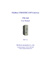
BYD COMPANY LIMITED
Rev. Aug. 24th 2012
IEC Installation Manual and User Manual for
BYD Photovoltaic Module
BYD(Shanghai) Industrial Co.Ltd
ADD:No.999 Xiangjing Road,Songjiang
Shanghai, 201611, P.R.China
TEL:+86-21-5777 8888
FAX:+86-21-5777 5086
www.byd.com.cn
BYD COMPANY LIMITED
Rev. Aug. 24th 2012
CONTENT
Foreword .................................................................................................................................................................................................................................................... 3
1. Product identification .......................................................................................................................................................................................................................... 3
1.1 Label .............................................................................................................................................................................................................................................................. 3
1.2 Barcode ......................................................................................................................................................................................................................................................... 3
2. Transportation and storage manual ................................................................................................................................................................................................. 4
3. Installation ............................................................................................................................................................................................................................................. 4
3.1 Warning ......................................................................................................................................................................................................................................................... 4
3.2 Mechanical installation ............................................................................................................................................................................................................................... 5
3.2.1 Mounting system ..................................................................................................................................................................................................................................... 5
3.2.2 Clamping .................................................................................................................................................................................................................................................. 6
3.3 Electric installation....................................................................................................................................................................................................................................... 8
3.3.1 Grounding ................................................................................................................................................................................................................................................ 8
3.3.2 General Installation ................................................................................................................................................................................................................................. 9
4. Maintenance and Care ....................................................................................................................................................................................................................... 10
4.1General ........................................................................................................................................................................................................................................................ 10
4.2 Module Cleaning ........................................................................................................................................................................................................................................ 10
5.Claim ................................................................................................................................................................................................................................................... 11
www.byd.com.cn
BYD COMPANY LIMITED
Rev. Aug. 24th 2012
1.2 Barcode
Foreword
Each module has only one bar code as follow:
This manual includes the transportation, installation and
maintenance of PV modules (hereafter referred to as “module”). Please
read this manual carefully before installing and using the modules.
Please get in touch with provider if you have any questions.
This manual is applied to all the standard modules of BYD
Company Limited.
Keep this guide in a safe place for future reference (care and
maintenance) and in case of sale or disposal of the modules.
NOTE: All the items in this manual also suit our 3 bus-bar
polycrystalline cell PV modules as well as monocrystalline cell
modules, and the pictures in the manual, which are 2 bus-bar
cell PV modules are just used for examples.
1. Product identification
1.1 Label
The label describes the product type, rated power, rated current,
rated voltage, open circuit voltage, short circuit current, weight,
dimensions etc.;
Typical label-A
Typical label-B
SH 120220 P630 AS68- 001
SH 120820 P630 AS68C001
SH——Manufacturer location, Shanghai;
120220——Date(YYMMDD);
P——P for Poly –Si, M for Mono-Si, L for Mono-Like Si;
6——6 for the cell dimension of 156*156,5 for the cell dimension
of 125*125mm;
30——the voltage of the modules;
AS68- or AS68C — — Engineering Code ,for different shifts,
materials etc;
001——Number of product components,3 digit sequence 0 to 999
for sequential production starting on each new day of production at 001.
BYD COMPANY LIMITED
2. Transportation and storage manual
Please observe the follow criterion after packing.
(1) Don’t lean ≥15° when transit packing boxes.
(2)Box up according to the sign of packing box.
(3)Be careful of transit, and don’t strike violence.
(4)The packing boxes should be protected from rain.
(5)Transportation condition should satisfy the packing boxes’
requirement and modules’ requirement of environment.
3. Installation
3.1 Warning
(1) Do not use mirrors or other magnifiers to artificially concentrate
sunlight on the modules.
(2) Do not touch live terminals with bare hands. Use insulated tools
for electrical.
(3) Although modules are quite durable, the glass can be broken
(and the module will no longer work properly) if it is dropped or hit by
tools or other objects.
(4) Under normal conditions, a photovoltaic module is likely to
experience conditions that produce more current and/or voltage than
reported at standard test conditions. Accordingly, the value of Isc and
Voc marked on this module should be multiplied by of 1.25 when
Rev. Aug. 24th 2012
determining component voltage ratings, conductor current ratings, fuse
sizes, and size of controls connected to the PV output.
(5) The installation work of the PV array can only be done under
the protection of sun-sheltering covers or sunshades and only qualified
person can install or perform maintenance work on this module.
(6) Systems should be installed by qualified personnel only and at
least two persons. The system involves electricity, and can be
dangerous if the personnel are not familiar with the appropriate safety
procedures.
(7) Follow the battery manufacture’s recommendations if batteries
are used with modules. Please observe the native rule and law when
install modules. You must obtain the architecture license.
(8) Please unpack carefully.
(9) Optical check before installation, to make sure there is no bug
in the packing and junction box as well as the surface of module.
(10)The users should design and build metallic bracket for
installing and bearing the weight of the PV modules. The brackets are
specially designed for users’ installation places such as the open land
or on the roof of houses.
(11)In most applications, PV modules should be installed in a
location where they will receive maximum sunlight throughout the year.
In the Northern Hemisphere, the modules should typically face south,
and in the Southern Hemisphere, the modules should typically face
north. When choosing a site, avoid trees, buildings or obstructions,
which could cast shadows on the solar. When choosing clamping or
insertion system, according to PV’s specification choosing appropriate
www.byd.com.cn
BYD COMPANY LIMITED
bracket, bracket should occur corrosion.
(12) Put the modules on the frame and put on the screws and then
combine them firmly after put on all the washers. All the screw caps
should be finished on the frame together firmly. The module frame is
made of anodized aluminum, and therefore corrosion can occur if the
module is subject to a salt-water environment with contact to a rack of
another type of metal. (Electrolysis Corrosion) if required. Stainless
steel washers can be placed between the solar module frame and
support structure to prevent this corrosion.
(13)Don't envelop the drain holes with other components when
install modules. Junction box should at the top of the module.
(14)Don’t grasp the junction box or cable when install modules.
(15) For roof application, the PV system must be mounted, over fire
resistant roof covering rated for the application. Do not use modules
near equipment or in places where flammable gases may be generated.
(16)The obliquity of PV array should follow the fire test request in
IEC 61730-2 when modules are installed in rooftop.
(17)The ambient temperature range of install location is
-40~+85°C.
Rev. Aug. 24th 2012
CAUTION: Please unpack in appropriate environment, and
use special tool. The modules should be water proof and
damp proof.
NOTE: BYD does not limit the materials of the installation if
the materials can be used outdoor for 25 years.
3.2 Mechanical installation
3.2.1 Mounting system
Use mounting holes to fix up as the follow figure ,and users must
tighten screws with the fastening torque. For a 5400Pa load, use eight
mounting holes.
Mounting holes introduction:
DANGER: One single module may generate more than 30V
DC when exposed to direct sunlight. If modules are in
series, voltage is equal to the sum of every module’s
voltage. If modules are in parallel, current is equal to the
sum of every module’s current. If many modules have been installed in series
or in parallel, please don’t touch by hand without any insulated equipment.
www.byd.com.cn
BYD COMPANY LIMITED
Model
measure
P6-18/
P6-24/
P6-27/
P6-30/
P6-36/
M6-18
M6-24
M6-27
M6-30
M6-36
L
1482
1325
1482
1640
1956
W
676
992
992
992
992
T
50/40
50/40
50/40
50/40
50/40
A
626
942
942
942
942
B
802
476
500
860
800
C
/
1076
1100
1360
1300
Rev. Aug. 24th 2012
clamps must have enough intensity to fix up modules
(recommending using stainless steel), and their structure couldn’t
shelter the cells.
Module installed with clamps on a long frame, “B’” is the
clamping range:
The detail of installation:
For a 5400Pa load, use four clamps on a long frame
model
P6-18/
P6-24/
P6-27/
P6-30/
P6-36/
M6-18
M6-24
M6-27
M6-30
M6-36
A
120
110
120
140
328
B
250
250
250
300
250
measure
For a 5400Pa load
NOTE: A is the distance form module edge to clamping range,
3.2.2 Clamping
B is the clamping range.
Modules could use the clamps as the follow picture, the
www.byd.com.cn
BYD COMPANY LIMITED
Installation:
Rev. Aug. 24th 2012
Installation:
CAUTION: This method just can be used less than 2400Pa
We advise users using the installation as the two pictures above.
Installation clamping methods on a short frame as below:
pressure and BYD does not take on the responsibility if the
module is broken with more than 2400Pa pressure.
(3) Insertion system
Modules could use insertion system as the follow picture to install,
and the insertion system must have enough intensity to fix up modules,
such as stainless steel and other appropriate metal to support PV
module. When insertion system install on a long frame, the insertion
system should not shelter the grounding holes.
For a 2400Pa load only, use four clamps on a short frame
For a 5400Pa load, use an insertion system on a long frame
www.byd.com.cn
BYD COMPANY LIMITED
We advise users using the installation method as the picture above
but not forcibly. This method can make modules have a good intensity.
Rev. Aug. 24th 2012
(2) For grounding and bonding requirements, please refer to
regional and national safety and electricity standards. If grounding is
required, use a recommended connector type, or an equivalent, for the
grounding wire. The grounding wire must be properly fastened to the
module frame to assure adequate electrical connection.
(3) The grounding has many methods . Only to assures safety is
OK, we recommend one method as below:
For a 2400Pa load only, use an insertion system on a short frame
CAUTION: This method just can be used less than 2400Pa
pressure and BYD does not take on the responsibility if the
module is broken with more than 2400Pa pressure.
3.3 Electric installation
3.3.1 Grounding
(1) Grounding: All module frames should be grounded for safety. It is
not recommended to use modules with different configurations
(grounding, wiring) in the same system. The combination of the material
of frame and the material of grounding would not result in galvanic
corrosion.
(4) All module frames should be grounded for safety. The
grounding connections between modules must be approved by a
qualified electrician, the grounding itself must be made by a qualified
electrician. The ground wire should be at least the same size as the
electrical conductors.
(5)In order to avoid the damage caused by PID, BYD suggests
that the negative of inverter should be grounded.
(6) The grounding system must be installed well.
www.byd.com.cn
BYD COMPANY LIMITED
CAUTION: BYD provide the mounting holes, drain holes
and grounding holes. These holes have passed the safety
testing. Installers can’t drill and block drain holes random.
Rev. Aug. 24th 2012
on system design, the type of inverter used and environmental
conditions. According to the system voltage (1000V) of IEC standard,
we recommend the maximum number of modules in series as below:
3.3.2 General Installation
Type
(1)When the system, the modules connect in series or parallel
generally, we recommend simple serial -connection and parallelconnection with the modes as below.
Serial –connection of modules:
The maximum number of
modules in series
BYD ***P6-18/M6-18
No more than forty
BYD ***P6-24/M6-24
No more than thirty-five
BYD ***P6-27/M6-27
No more than thirty
BYD ***P6-30/M6-30
No more than twenty-five
BYD ***P6-36/M6-36
No more than twenty
(5)There is no limitation on the number of modules that can be
connected in parallel, the number of modules is determined by system
design parameters such as current or power output. Every PV array in
parallel should install protection circuit.
(6) Please refer to local regulations to determine the system wires
size, type and temperature. To prevent the cables and the connectors
from overheating, the cross section of the cables and the capacity of the
connectors must be selected to suit the maximum system short circuit
current (The recommended cable cross section is 4mm2 for a single
module and if rated current of a connector is higher than 10A).
Parallel- connection of modules
(2) The bypass diode have a Rated Average Forward Current 10A
at least, and a Rated Repetitive Peak Reverse Voltage 40V at least.
(3) The maximum number of series connected modules depends
www.byd.com.cn
NOTE: Please note that the upper limit temperature of
cable is 90°C, and the upper limit temperature of the
connector is 100°C.
BYD COMPANY LIMITED
4. Maintenance and Care
Rev. Aug. 24th 2012
CAUTION: If the system goes wrong, please let the
professional engineers deal with it. Others should not
disassemble the system optionally.
4.1General
The inspection should confirm the following:
(1) Check the module’s setting of machine on time. Check the
support equipment (fastness, erosion, bolts and nuts, especially the
place where the wind or shake is hard. Ensure the fixing is fast. If not
fast, screw them down.) If the condition permits, the metal fittings that
fasten or support the modules should be protected from the eroded,
such as the bolts and nuts. A first check after 12 months and an
additional check after 120 months should be made.
(2)Check the module’s electric line (connection to the equipment
and earth) for a settled time. Check the grounded resistance satisfying
the designation request. If the connection is not fast, jointing it. After the
thunderstorm or before, check the junction box and other protectors for
the thunder. If invalidation, replace it according to the request.
(3)Check the lead connector for the leakage current and deal with
it. Be care for the rainy or snowy weather which affects the leakage
current. When checking the lead, People must take the insulated sets
(such as tools and gloves). Don’t touch the uncovered lead or the
connectors with uncovered hands. Check the connections of each part
to ensure them fast, if not, connect them. Wipe the dust up from the
equipment regularly to keep it clean.
(4) If the module needs repaired, covered with fabric or other
material. Or it may produce high voltage under the sun.
4.2 Module Cleaning
Over dirt and dust can accumulate on the glass surface of the
module, reducing its power output.BYD recommends periodic cleaning
of PV modules to ensure maximum power output especially when the
modules do not have the expected power output. Check the glass to
ensure the surface is good before cleaning. If it is broken, please do not
clean and inform to the purchaser and maintenance. Do not wear the
watch or jewellery when cleaning. Use the soft fabric clean out the dust.
If the dust is hard to wipe out, use the water to clean. Then use the
clean fabric wiping up the water carefully. Do not use hard tools or
mordant solution wiping the module for avoiding leaving scrape so as to
affect the light transmission efficiency. The power attenuation caused
by the scrape is beyond our guarantee range. Do not wipe on the day,
and you had better to clean on the night or morning without strong
sunshine. Do not use the cold water to clean the module so as to
avoiding broking the glass.
www.byd.com.cn
BYD COMPANY LIMITED
Rev. Aug. 24th 2012
5.Claim
NOTE: A note provides information about installation,
As the adherence to this manual and the conditions or methods of
installation, operation, use and maintenance of photovoltaic (PV)
products are beyond BYD’s control, BYD does not accept responsibility
and expressly disclaims liability for any loss, damage, or expense
arising out of or in any way connected with such installation, operation,
use or maintenance.
The information in this manual is based on BYD’s knowledge and
experience and is believed to be reliable. The manual provides
reference, and consumer could choose appropriate installation
according to place and environment.
BYD reserves the right to change the manual, the PV produce, the
specifications, or product information sheets without prior notice.
www.byd.com.cn
operation, or maintenance of the module that is important
to know, but it is not necessarily hazardous.
CAUTION: A caution message indicate a potential threat to
minor injury, or alerts against behavior that can lead to
property damage.
DANGER: A danger message indicates a hazard in the
immediate area which, if not avoided, can result in death or
serious injury.