1
KOC100 Series Vector Control User Manual
Preface
Preface
Thank you for purchasing the KOC100 series frequency inverter developed by KCLY.
The high-performance KOC100 series frequency inverter has the following features:
1) Voltage classes
It provides coverage of single-phase 220 V, three-phase 220 V, three-phase 380 V.
2) Motor types
It supports V/F and open-loop vector control of three-phase AC asynchronous motor.
3) Communication protocols
It supports communication via Modbus-RTU.
4) Super speed sensor-less vector control algorithm
It adopts high-speed response, enhanced low-frequency loading capacity and supports torque control of
SVC, which will bring you a new using experience.
KOC100 series frequency inverter is a continuable and vigorous product, and our company will offer
customized service to our customers!
Before unpacking, please check carefully:
•
Whether the nameplate model of frequency inverter are consistent with your order ratings. The box
contains the frequency inverter and user manual.
•
Whether the frequency inverter is damaged during transportation. If you find any omission or damage,
please contact us or your local supplier immediately.
First-time Use
For the users who use this product for the first time, read the manual carefully. If in doubt concerning some
functions or performances, contact the technical support personnel to ensure correct use.
Due to the continuous improvement of frequency inverter, this document will be updated without prior
notice.
KOC100 series frequency inverter complies with the following international standards. All products have
passed the CE certification.
IEC/EN61800-5-1: 2003 Variable speed electric drive system safety requirements;
IEC/EN61800-3: 2004 Variable speed electric drive system, Part 3: The Electro Magnetic Compatibility
(EMC) Standards of Product and its specific testing methods.
1
Contents
KOC100 Series Vector Control User Manual
Contents
Preface ______________________________________________________________________________ 1
Contents _____________________________________________________________________________ 2
Chapter 1 Safety Information and Precautions ____________________________________________ 5
1.1 Safety Information ___________________________________________________________________ 5
1.2 General Precautions __________________________________________________________________ 7
Chapter 2 Product Information ________________________________________________________ 10
2.1 Designation Rules ___________________________________________________________________ 10
2.2 Nameplate _________________________________________________________________________ 10
2.3 KOC100 Series Frequency Inverter _____________________________________________________ 10
2.4 Technical Specifications _______________________________________________________________ 11
2.5 Product appearance and installation dimension ____________________________________________ 14
2.6 Daily maintenance of frequency inverters ________________________________________________ 15
2.7 Warranty Items _____________________________________________________________________ 16
2.8 Selection Guide of braking component ___________________________________________________ 16
Chapter 3 Installation of Frequency Inverter ______________________________________________ 18
3.1 Installation environment ______________________________________________________________ 18
3.2 Installation direction and space _________________________________________________________ 18
3.3 Peripheral Devices Connection Diagram _________________________________________________ 19
3.4 Instructions of Main Circuit Peripheral Devices ____________________________________________ 20
3.5 Model Selection of Main Circuit Peripheral Devices ________________________________________ 21
3.6 Removal and mounting of operating panel and cover ________________________________________ 21
3.7 Connection Terminals Diagram Description _______________________________________________ 23
3.8 Sketch and Description of Main Circuit Terminals __________________________________________ 23
3.9 Cautions for Main Circuit Wiring _______________________________________________________ 24
3.10 Control Circuit and Main Circuit Terminals Description ____________________________________ 26
Chapter 4 Operation and display ________________________________________________________ 31
4.1 Instruction of operation and display _____________________________________________________ 31
4.2 Viewing and Modifying Function Codes _________________________________________________ 32
4.3 Parameter Display Mode______________________________________________________________ 33
4.4 Operation Mode of User-defined Parameters ______________________________________________ 34
2
KOC100 Series Vector Control User Manual
Contents
4.5 Monitoring Status Parameters __________________________________________________________ 35
4.6 Password Setting ____________________________________________________________________ 35
4.7 Motor Parameter Auto-tuning __________________________________________________________ 35
Chapter 5 Function Code Table _________________________________________________________ 37
Chapter 6 Description of Function Codes _________________________________________________ 73
6.1 Group b0: Basic Function Parameters____________________________________________________ 73
6.2 Group b1: Start/Stop Control Parameters _________________________________________________ 81
6.3 Group b2: Auxiliary Functions _________________________________________________________ 84
6.4 Group b3: Input Terminals ____________________________________________________________ 89
6.5 Group b4: Output Terminals ___________________________________________________________ 96
6.6 Group b5: Pulse/Analog input terminals _________________________________________________ 102
6.7 Group b6: Pulse/analog output terminals ________________________________________________ 104
6.8 Group b7: Virtual digital input (VDI)/digital output (VDO) terminals __________________________ 105
6.9 Group b8: AI/AO Correction _________________________________________________________ 108
6.10 Group b9: Operation Panel and Display ________________________________________________ 109
6.11 Group bA: Communication parameters _________________________________________________ 113
6.12 Group bb: Fault and Protection ________________________________________________________ 115
6.13 Group bC: Fault detection Parameters _________________________________________________ 122
6.14 Group C0: Process Control PID Function _______________________________________________ 123
6.15 Group C1:Multi-function ___________________________________________________________ 128
6.16 Group C2: Simple PLC _____________________________________________________________ 129
6.17 Group C3: Swing Frequency, Fixed Length and Count ____________________________________ 131
6.18 Group d0: Motor 1 Parameters _______________________________________________________ 133
6.19 Group d1: Motor 1 vector control parameters ____________________________________________ 136
6.20 Group d2: Motor 1 V/F Control Parameters _____________________________________________ 139
6.21 Group d3 to d5: Relevant parameters of motor 2 _________________________________________ 143
6.22 Group d6: Control Optimization Parameters ____________________________________________ 143
6.23 Group U0: Monitoring Parameters ____________________________________________________ 145
6.24 Group A0: System parameters _______________________________________________________ 150
6.25 Group A1: User-Defined Function Codes _______________________________________________ 152
Chapter 7 EMC (Electromagnetic compatibility) _________________________________________ 153
7.1 Definition ________________________________________________________________________ 153
3
Contents
KOC100 Series Vector Control User Manual
7.2 EMC Standard Description ___________________________________________________________ 153
7.3 EMC Guide _______________________________________________________________________ 153
Chapter 8 Fault Diagnosis and Solution ________________________________________________ 156
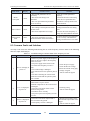
8.1 Fault Alarm and Countermeasures _____________________________________________________ 156
8.2 Common Faults and Solutions ________________________________________________________ 160
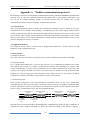
Appendix A Modbus communication protocol ___________________________________________ 162
4
KOC100 Series Vector Control User Manual
Chapter 1
Safety Information and Precautions
Safety Information and Precautions
In this manual, the notices are graded based on the degree of danger:
•
DANGER indicates that failure to comply with the notice will result in severe personal injury or
even death.
•
WARNING indicates that failure to comply with the notice will result in personal injury or
property damage.
Read this manual carefully so that you have a thorough understanding. Installation, commissioning or
maintenance may be performed in conjunction with this chapter. KCLY will assume no liability or
responsibility for any injury or loss caused by improper operation.
1.1 Safety Information
1.1.1 Before installation
DANGER
1. Do not use damaged or missing components frequency inverter. Failure to comply will result in personal
injury.
2. Please use the electric motor with upper B insulation class. Failure to comply will result in personal
injury.
1.1.2 During installation
DANGER
1. Install the frequency inverter on incombustible objects such as metal, and keep it away from combustible
materials. Failure to comply may result in a fire.
WARNING
2. When two frequency inverters are laid in the same cabinet, arrange the installation positions properly to
ensure the enough cooling effect.
3. Do not drop wire residue or screw into the frequency inverter. Failure to comply will result in damage to
the frequency inverter.
1.1.3 Wiring
DANGER
1. Wiring must be performed only by qualified personnel under instructions described in this manual.
Failure to comply may result in unexpected accidents.
2. A circuit breaker must be used to isolate the power supply and the frequency inverter. Failure to comply
may result in a fire.
3. Ensure that the power supply is cut off before wiring. Failure to comply may result in electric shock.
5
Safety Information and Precautions
KOC100 Series Vector Control User Manual
4. Connect the frequency inverter to ground properly by standard. Failure to comply may result in electric
shock.
WARNING
5. Never connect the power supply cables to the output terminals (U, V, W) of the Frequency inverter.
Failure to comply will result in damage to the frequency inverter.
6. Make sure that all the connecting wires comply with the requirement of EMC and the safety standard in
the region. Use wire sizes recommended in the manual. Failure to comply may result in accidents.
1.1.4 Before power-on
DANGER
1. Check that the following requirements comply with:
The voltage class of the power supply is consistent with the rated voltage class of the frequency inverter.
The input terminals (R, S, T) and output terminals (U, V, W) are properly connected.
No short-circuit exists in the peripheral circuit.
The wiring is fastened.
Failure to comply will result in damage to frequency inverter.
2. Cover the frequency inverter properly before power-on to prevent electric shock.
WARNING
3. Do not perform the voltage resistance test on any part of the frequency inverter because such test has
been done in the factory. Failure to comply will result in accidents.
4. All peripheral devices must be connected properly under the instructions described in this manual.
Failure to comply will result in accidents.
1.1.5 After power-on
DANGER
1. Do not open the frequency inverter’s cover after power-on to prevent from electric shock.
2. Do not touch the frequency inverter and its peripheral circuit to prevent from electric shock.
3. Do not touch the terminals of the frequency inverter (including the control terminals). Failure to comply
may result in electric shock.
4. Do not touch the U, V, W terminal or motor connecting terminals when frequency inverter automatically
does safety testing for the external high-voltage electrical circuit. Failure to comply may result in electric
shock.
WARING
5. Note the danger during the rotary running of motor when check the parameters. Failure to comply will
result in accidents.
6. Do not change the factory default settings of the frequency inverter. Failure to comply will result in
damage to the frequency inverter.
6
KOC100 Series Vector Control User Manual
Safety Information and Precautions
1.1.6 During operation
DANGER
1. Do not go close to the equipment when selected the restart function. Failure to comply may result in
personal injury.
2. Do not touch the fan or the discharging resistor to check the temperature. Failure to comply will result in
personal injury.
3. Signal detection must be performed only by qualified personal during operation
WARNING
4. Avoid objects falling into the frequency inverter when it is running. Failure to comply will result in
damage to frequency inverter.
5. Do not start/stop the frequency inverter by turning the contactor ON/OFF. Failure to comply will result
in damage to the frequency inverter.
1.1.7 Maintenance
DANGER
1. Do not repair or maintain the frequency inverter at power-on. Failure to comply will result in electric
shock.
2. Repair or maintain the frequency inverter only after the charge light on frequency inverter is powered off.
This allows for the residual voltage in the capacitor to discharge to a safe value. Failure to comply will
result in personal injury.
3. Repair or maintenance of the frequency inverter may be performed only by qualified personnel. Failure
to comply will result in personal injury or damage to the frequency inverter.
1.2 General Precautions
1.2.1 Motor insulation test
Perform the insulation test when the motor is used for the first time, or when it is reused after being stored
for a long time, or in a regular check-up, in order to prevent the poor insulation of motor windings from
damaging the frequency inverter. The motor must be disconnected from the frequency inverter during the
insulation test. A 500-V mega-Ohm meter is recommended for the test. The insulation resistance must not
be less than 5 MΩ.
1.2.2 Thermal protection of motor
If the rated capacity of the motor selected does not match that of the frequency inverter, especially when
the frequency inverter's rated power is greater than the motor's, adjust the motor protection parameters on
the operation panel of the frequency inverter or install a thermal relay in the motor circuit for protection.
1.2.3 Running at over 50 Hz
The frequency inverter provides frequency output of 0 to 3000 Hz (Up to 300 Hz is supported if the
frequency inverter runs in VC and SVC mode). If the frequency inverter is required to run at over 50 Hz,
consider the bearable capacity of the machine.
7
Safety Information and Precautions
KOC100 Series Vector Control User Manual
1.2.4 Vibration of mechanical device
The frequency inverter may encounter the mechanical resonance point at some output frequencies, which
can be avoided by setting the skip frequency.
1.2.5 Motor heat and noise
The output of the frequency inverter is pulse width modulation (PWM) wave with certain harmonic
frequencies, and therefore, the motor temperature, noise, and vibration are slightly greater than those motor
runs at grid power frequency (50 Hz).
1.2.6 Voltage-sensitive device or capacitor at output side of the Frequency inverter
Do not install the capacitor for improving power factor or lightning protection voltage-sensitive resistor at
the output side of the frequency inverter because the output of the frequency inverter is PWM wave.
Otherwise, the frequency inverter may suffer transient over current and even to be damaged.
1.2.7 Contactor at the Input/Output side of the frequency inverter
When a contactor is installed between the input side of the frequency inverter and the power supply, the
frequency inverter must not be started or stopped by switching the contactor on or off. If the frequency
inverter has to be operated by the contactor, ensure that the time interval between switching is at least one
hour. Since frequently charge and discharge will shorten the service life of the capacitor inside of
frequency inverter.
When a contactor is installed between the output side of the frequency inverter and the motor, do not turn
off the contactor when the frequency inverter is active. Otherwise, IGBT modules inside of frequency
inverter may be damaged.
1.2.8 When input voltage is over rated voltage range
The frequency inverter must not be used over the allowable voltage range specified in this manual.
Otherwise, the frequency inverter's components may be damaged. If required, use a corresponding voltage
transformer device.
1.2.9 Prohibition of three-phase input changed into two-phase input
Do not change the three-phase input of the frequency inverter to two-phase input. Otherwise, a fault will be
result or the frequency inverter will be damaged.
1.2.10 Surge suppressor
The frequency inverter has a built-in voltage dependent resistor (VDR) for suppressing the surge voltage.
For frequently surge place, please add extra surge voltage protection device at input side of frequency
inverter.
Note: Do not connect the surge suppressor at the output side of the AC.
1.2.11 Altitude and de-rating
In places where the altitude is above 1000 m and the cooling effect reduces due to thin air, it is necessary to
de-rate the frequency inverter. Please contact our company for technical support.
8
KOC100 Series Vector Control User Manual
Safety Information and Precautions
1.2.12 Some special usages
If wiring that is not described in this manual such as common DC bus is applied, please contact the agent or
our company for technical support.
1.2.13 Disposal
The electrolytic capacitors on the main circuits and PCB may explode when they are burnt. Poisonous gas
is generated when the plastic parts are burnt. Please treat them as industrial waste.
1.2.14 Adaptable Motor
•
The standard adaptable motor is adaptable four-pole squirrel-cage asynchronous induction motor. For
other types of motor, select a proper frequency inverter according to the rated motor current. If user uses
inverter for permanent magnet synchronous motor, please contact my company for technical support.
•
The cooling fan and rotor shaft of non-variable-frequency motor are coaxial, which results in reduced
cooling effect when the rotational speed decreasing. If variable speed is required, add a more powerful fan
or replace it with variable-frequency motor in applications where the motor overheats easily.
•
The standard parameters of the adaptable motor have been configured inside the frequency inverter. It
is still necessary to perform motor auto-tuning or modify the default values based on actual conditions.
Otherwise, the running result and protection performance will be affected.
•
The frequency inverter may alarm or even be damaged when short-circuit exists on cables or inside
the motor. Therefore, perform insulation short-circuit test when the motor and cables are newly installed or
during routine maintenance. During the test, make sure that the frequency inverter is disconnected from the
tested parts.
9
Product Information
KOC100 Series High Performance Vector Control User Manual
Chapter 2
Product Information
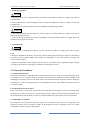
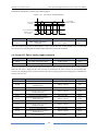
2.1 Designation Rules
Figure 2-1
Designation rules
KOC100 - 1R5T4
Product Series
Voltage Class (2-220V,
Power Class
4-380V)
/ Model Type
Phase (S-Single-phase,
T-Three-phase)
Mark
0R4
R75
1R5
2R2
Motor Power(KW)
0.4
0.75
1.5
2.2
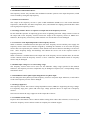
2.2 Nameplate
Figure 2-2
Nameplate
MODEL: KOC100-1R5T4
POWER: 1.5KW
INPUT: 3PH AC 380V 50/60Hz 5.0A
OUTPUT: 3PH AC 0~380V 0~300Hz 3.8A
VERSION:
Barcode
S/N:
Shenzhen KCLY Electric Co., Ltd.
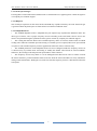
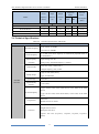
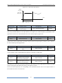
2.3 KOC100 Series Frequency Inverter
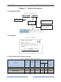
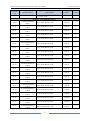
Table 2-1
Model
Models and technical data of KOC100
Power
Input
Output
Capacity
Current
Current
(KVA)
(A)
(A)
Single-phase 220V,
Adaptable
Thermal
Motor
Power
Consumption
KW
HP
(KW)
50/60Hz
KOC100-0R4S2
1.0
5.4
2.3
0.4
0.5
0.016
KOC100-R75S2
1.5
8.2
4
0.75
1
0.030
KOC100-1R5S2
3
14
7
1.5
2
0.055
10
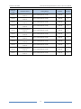
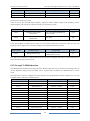
KOC100 Series High Performance Vector Control User Manual
Model
Product Information
Power
Input
Output
Capacity
Current
Current
(KVA)
(A)
(A)
Adaptable
Thermal
Motor
Power
Consumption
KW
HP
(KW)
Three-phase 380V,50/60Hz
KOC100-0R4T4
1.0
2.5
1.3
0.4
0.5
0.015
KOC100-R75T4
1.5
3.4
2.1
0.75
1
0.027
KOC100-1R5T4
3
5
3.8
1.5
2
0.050
KOC100-2R2T4
4
5.8
5.1
2.2
3
0.066
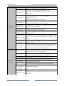
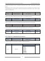
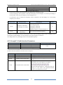
2.4 Technical Specifications
Table 2-2
Technical specifications of KOC100
Item
Specifications
Maximum frequency
Carrier frequency
Input frequency
resolution
Control mode
Startup torque
Standard
functions
Speed range
Speed stability
accuracy
Vector control: 0~300 Hz;
V/F control: 0~3000 Hz
0.5–16 kHz (The carrier frequency is automatically adjusted based on
the load features.)
Digital setting: 0.01 Hz;
Analog setting: maximum frequency x 0.025%
Sensor-less vector control (SVC);
Voltage/Frequency (V/F) control
G type: 0.5 Hz/150% (SVC);
P type: 0.5 Hz/100%
1:100 (SVC)
1:1000 (VC)
±0.5% (SVC)
G type: 60s for 150% of the rated current, 3s for 180% of the rated
Overload capacity
current;
P type: 60s for 120% of the rated current, 3s for 150% of the rated
current
Torque boost
Auto boost;
Manual boost 0.1%~30.0%
Three modes:
Straight-line V/F curve;
V/F curve
Multi-point V/F curve;
N-power V/F curve (1.2-power, 1.4-power, 1.6-power, 1.8-power,
square)
11
Product Information
KOC100 Series High Performance Vector Control User Manual
V/F separation
Acceleration/deceler
ation curve
Two types: complete separation; half separation
Straight-line or S-curve acceleration/deceleration modes
Four groups of acceleration/deceleration time with the range of
0.00s~65000s
DC braking frequency: 0.00 Hz ~ maximum frequency
DC braking
Braking time: 0.0~36.0s
Braking trigger current value: 0.0%~100.0%
JOG control
Standard
functions
Simple PLC,
multiple speeds
It realizes up to 16 speeds via the built-in PLC function or
combination of DI terminal states.
It realizes closed loop control system easily.
Auto voltage
It can keep constant output voltage automatically when the power grid
Overvoltage/ Over
current stall control
Rapid current limit
function
Torque limit and
control
High performance
Instant power off not
stop
Rapid current limit
Virtual I/Os
functions
JOG acceleration/deceleration time: 0.00s~65000s
Built-in PID
regulation (AVR)
Individualized
JOG frequency range: 0.00Hz~50.00 Hz
Timing control
Multi-motor
voltage fluctuates.
The current and voltage are limited automatically during the running
process so as to avoid frequently tripping due to overvoltage / over
current.
It can protect the proper running of the inverter, and furthest avoid the
over-current faults.
(Excavator characteristics) It can limit the torque automatically and
prevent frequently over current tripping during the running process.
Torque control can be implemented in the VC mode.
Control of asynchronous motor is implemented through the high
performance current vector control technology.
The load feedback energy compensates the voltage reduction so that
the frequency inverter can continue to run for a short time.
To avoid frequently over current faults of the frequency inverter.
Five groups of virtual DI/DO can realize simple logic control.
Time range: 0.0~6500.0 minutes
Two motors can be switched by two groups of motor parameters.
switchover
Multiple
communication
It supports RS-485 Modbus.
protocols
Advanced
background software
It supports the operation of frequency inverter parameters and virtual
oscillograph function, by which the state of frequency inverter can be
monitored.
12
KOC100 Series High Performance Vector Control User Manual
Product Information
key panel
Running command
giving
Control terminals
Serial communication port
You can switch between these giving in various ways.
There are 10 kinds frequency giving: digital setting, analog voltage
Frequency giving
setting, analog current setting, pulse setting and serial communication
port setting. You can switch between these giving in various ways.
Auxiliary frequency
RUN
giving
There are 10 kinds auxiliary frequency giving. It can implement tiny
tuning of auxiliary frequency and frequency synthesis.
Standard:
5 digital input (DI) terminals
Input terminal
2 analog input (AI) terminals, one of which only supports 0V~10 V
voltage input and the another supports 0V~10 V voltage input or 0~20
Ma current input
Standard
1 digital output (DO) terminal
Output terminal
1 relay output terminal
1 analog output (AO) terminals, supports 0~20 Ma current output or
0V~10 V voltage output
LED display
It displays the parameters.
LCD display
It is optional, supports panel display in Chinese or English language.
Parameters copy
Optional LCD keypad can copy parameters.
operation on the
Key locking and
It can lock the keys partially or completely and define the function
key panel
function selection
range of some keys so as to prevent misoperation.
Display and
Motor short-circuit detection at power-on, input/output phase loss
Protection mode
protection, over current protection, overvoltage protection, less voltage
protection, overheat protection and overload protection,etc.
Installation location
Altitude
Environment
Ambient temperature
Indoor, no direct sunlight, dust, corrosive gas, combustible gas, oil
smoke, vapour, drip or salt.
Lower than 1000 m
-10°C~ +40°C (de-rated if the ambient temperature is between 40°C
and 50°C)
Humidity
Less than 95%RH, without condensing
Vibration
Less than 5.9 m/s2 (0.6 g)
Storage temperature
-20°C ~ +60°C
13
Product Information
KOC100 Series High Performance Vector Control User Manual
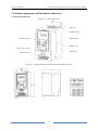
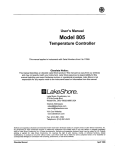
2.5 Product appearance and installation dimension
2.5.1 Product appearance
Figure 2-3
Product appearance
Fan cover
Mounting hole
Bottom cover
Operating panel
Middle cover
Trade mark sticker
Nameplate
Terminal cover
Figure 2-4
Appearance and installation dimension of KOC100 series
14
KOC100 Series High Performance Vector Control User Manual
Product Information
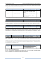
2.5.2 Appearance and Installation Hole Dimension (mm) of KOC100 Frequency Inverter
Table 2-3
Appearance and installation hole dimension (mm) of KOC100 frequency inverter
Model
KOC100-0R4S2
KOC100-R75S2
KOC100-1R5S2
W
82.6
Appearance and installing dimension(mm)
W1
H
H1
D
Single-phase 220V
65.5
166
Φd
154
118.5
Φ5.2
154
118.5
Φ5.2
Weight
(kg)
Three-phase 380V
KOC100-0R4T4
KOC100-R75T4
KOC100-1R5T4
KOC100-2R2T4
82.6
65.5
166
2.5.3 Dimension figure of connecting terminals
Omitted
2.6 Daily maintenance of frequency inverters
2.6.1 Daily maintenance
Due to the influence of temperature, humidity, dust and vibration, it will lead to poor heat dissipation and
component aging of frequency inverter, and results in potential failure or reducing the service life of frequency
inverter. Therefore, it is necessary to do daily and regular maintenance of the frequency inverter.
Daily check items:
1) Check if the sound is normal during the running of the motor;
2) Check if there is a vibration during the running of the motor;
3) Check whether the installation environment of frequency inverter has changed;
4) Check if the cooling fan of frequency inverter is working correctly, the cooling air duct is clear;
5) Check if the frequency inverter is overheating;
6) Make sure that the frequency inverter should always be kept in a clean state;
7) Clear up effectively the dust on the surface of the frequency inverter, prevent the dust from entering into the
inside of the frequency inverter, especially for the metal dust;
8) Clear up effectively the oil and dust on the cooling fan of frequency inverter.
2.6.2 Regular inspection
Please regularly check frequency inverter, especially for the difficult checking place of running.
Regular inspection items:
1) Check the air duct and clear up regularly;
2) Check if there are any loose screws;
3) Check if the inverter has been corroded;
4) Do insulation test for the main circuit.
Note:
When using the megger(please use the DC 500V meg ohm meter) to measure the insulation resistance, you shall
disconnect the main circuit to the frequency inverter. Do not use the insulation resistance meter to test the control
circuit. Do not to do the high voltage test (It has been done when the frequency inverter producing in factory.)
15
Product Information
KOC100 Series High Performance Vector Control User Manual
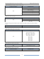
2.6.3 Wearing parts replacement
The wearing parts of frequency inverter include the cooling fan and filting electrolytic capacitor, its service life
is closely related to the using environment and maintenance status. The general service life is:
Part Name
Service Life
Fan
2 to 3 Years
Electrolytic capacitor
4 to 5Years
The user can confirm the replace time according to the running time.
1) Possible reasons for the damage of cooling fan: bearing wear and blade aging. Distinguish standard: Any
cracks in the fan blade, any abnormal vibration sound during the starting of frequency inverter.
2) Possible reasons for the damage of filting electrolytic capacitor: poor quality of the input power supply, the
environment temperature is higher, the load change frequently and the electrolyte aging. Distinguish standard:
Any leakage of its liquid, if the safety valve is protruding, electrostatic capacitance and insulation resistance
measurement.
2.6.4 Storage of the frequency inverter
After buying the frequency inverter, users shall pay attention to the temporary and long-term storage as
following:
1) Store the frequency inverter in the original packaging;
2) Long-term storage can lead to the degradation of electrolytic capacitors, and must ensure to power on for once
within 2 years. And the power-on time is at least 5 hours. The input voltage must slowly rise to the rating by
using the voltage regulator.
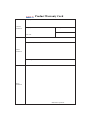
2.7 Warranty Items
1) Warranty only refers to frequency inverter.
2) Under normal use, if there is any failure or damage, our company is responsible for the warranty within 12
months. (Leave factory date is subjected to the S/N on the frequency inverter nameplate or the contract). When
over 12 months, reasonable maintenance fee will be charged;
3) During 12 months, if the following situation happens, certain maintenance fee will be charged;
a, The users don’t follow the manual stated makes the frequency inverter damaged;
b, The damage caused by fire, flood and abnormal voltage;
c. The damage caused by using the frequency inverter for abnormal functions;
d. The relevant service fee is calculated according to the manufacturer’s standard, if there is contract, then it
carries out subject to the contract.
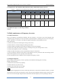
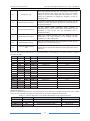
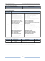
2.8 Selection Guide of braking component
Table 2-5 is the recommended value of braking resistor, users can select the different resistance value and power
according to the actual situation,(but the resistance value must not be less than the recommended value in the
table, and the power can be bigger.) The selection of braking resistance need to be confirmed according to the
power that the motor generated in the practical application systems, and is relevant to the system inertia,
deceleration time, the energy of the potential energy load, needs customers to choose according to actual
situation. The greater the inertia the shorter deceleration time is needed and more frequently braking, so the
braking resistor needs the one with bigger power but smaller resistance value.
16
KOC100 Series High Performance Vector Control User Manual
Product Information
2.8.1 Selection of braking resistance value
When braking, almost all the renewable energy of motor is consumed on the braking resistor.
According to the formula: U * U/R = Pb
In the formula:
U --- The braking voltage when the system brake stably (different system is different, for the 380VAC system
generally take 700V)
R – Braking resistor
Pb – Power of braking
2.8.2 Selection power of braking resistor
In theory the power of braking resistor is consistent with the braking power, but it need to be taken into
consideration that the braking resistor power will derate to 70%.
According to the formula: 0.7*Pr=Pb*D
In this formula:
Pr----Power of resistor
D---- Braking proportion (the proportion that the regeneration process accounts for the whole process)
Elevator---- 20%~30%
Uncoiling and coiling machine---- 20%~30%
Centrifugal machine---- 50%~60%
Occasionally braking load---- 5%
Other machine generally-----10%
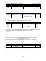
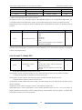
Table 2-4 Braking components selection table of KOC100 inverter
Recommend
Recommend
Model
power of braking
resistance value of
Braking unit
Remarks
resistor
braking resistor
Single-phase 220V
KOC100-0R4S2
80W
≥ 200Ω
KOC100-R75S2
80W
≥ 150Ω
KOC100-1R5S2
100W
≥ 100Ω
Built-in as
standard
No special
instructions
Built-in as
standard
No special
instructions
Three-phase 380V
KOC100-0R4T4
80W
≥ 200Ω
KOC100-R75T4
80W
≥ 150Ω
KOC100-1R5T4
100W
≥ 100Ω
KOC100-2R2T4
100W
≥ 70Ω
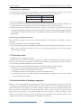
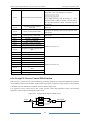
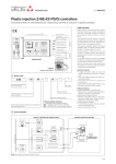
2.9.3 Braking resistor connection description
The braking resistor connection of KOC100 series frequency inverter is showed as below:
Figure 2-5
Braking resistor connection scheme
P+
Braking
Inverter
Resistor
PB
17
Installation of AC drive
KOC100 Series High Performance Vector Control User Manual
Chapter 3 Installation of Frequency Inverter
3.1 Installation environment
1. The place with indoor vents or ventilation devices.
2. The environment temperature shall be -10℃~40℃. If the temperature is over 40℃but less than 50℃, better to
take down the cover of frequency inverter or open the front door of cabinet to facilitate heat dissipation.
3. Try to avoid high temperature and wet place; the humidity shall be less than 90% without frost deposit.
4. Avoid direct sunlight.
5. Keep away from flammable, explosive and corrosive gas and liquid.
6. No dust, floating fiber and metal particles.
7. Install on the place without strongly vibration. And the vibration should be not over 0.6G, Especially pay
attention to far away from the punching machine, etc.
8. Keep away from electromagnetic interference source.
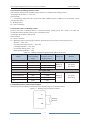
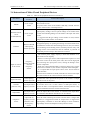
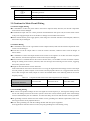
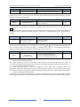
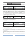
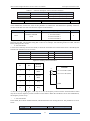
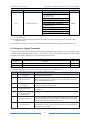
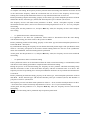
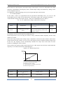
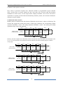
3.2 Installation direction and space
In order to not affect the service life of frequency inverter and reduce its performance, note for its installation
direction and space and correctly fasten it.
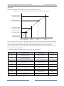
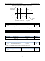
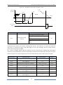
Figure3-1
Ventilating duct installation dimension diagram of frequency inverter
Convection
outlet
Air
circulation
area
Air
circulation
area
Air inlet
Power class
≤2.2kW
Installation dimension
A
B
≥ 20mm
≥ 100mm
Please install the frequency inverter vertically, to send out the heat upward, and pay attention to direction of
frequency inverter to avoid inversion.
If there are several units of frequency inverter installed, please install them side by side, do not to install up and
down.
18
KOC100 Series High Performance Vector Control User Manual
Installation of AC drive
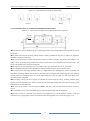
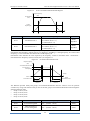
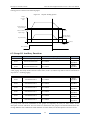
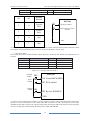
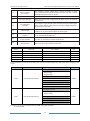
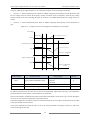
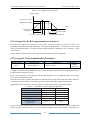
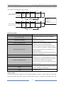
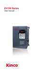
3.3 Peripheral Devices Connection Diagram
Fig 3-2
Peripheral Devices Connection
AC Power supply
Circuit breaker or
leakage circuit breaker
AC Contactor
Input AC reactor
Input AC noise filter
DC reactor
AC drive
Grounding
Output AC noise filter
Braking resistor
Output AC reactor
Motor
Grounding
19
Installation of AC drive
KOC100 Series High Performance Vector Control User Manual
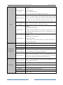
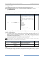
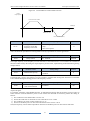
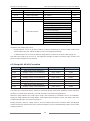
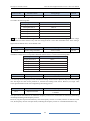
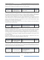
3.4 Instructions of Main Circuit Peripheral Devices
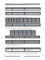
Table 3-1
Parts Name
Main circuit peripheral devices use instructions
Installation
Location
MCCB
Front of input
circuit
Residual-current
circuit
breaker(RCCB)
Front of input
circuit
Function Description
The capacity of the circuit breaker shall be 1.5 to 2 times of the rated
current of the inverter.
The protect time of the circuit breaker shall fully consider the time
features of the inverter overload protection.
As the inverter output is the high-frequency pulse output, there will be
high-frequency leakage current. Special leakage circuit breaker shall
be used when installing leakage circuit breaker at the input side of the
inverter.
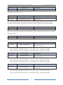
It is suggested that B type leakage circuit breaker be used, and the
leakage current value shall be set as 300mA.
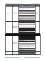
Between MCCB
and frequency
inverter input side
Frequently open and close of contactor will cause inverter failure, so
the highest frequency for opening and closing of contactor shall be not
exceeded than 10 times/min when braking resistor is used, to avoid the
over-hot damage of the braking resistor, thermal protection relay with
braking resistor over-hot detection shall be installed, by terminal of
the thermal protection relay to disconnect the contactor.
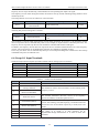
Input AC reactor
or DC reactor
Frequency
inverter input side
/ near the
Frequency
inverter
1. The inverter power supply capacity is more than 600kVA or 10
times of the inverter capacity.
2. If there is switch type reactive-load compensation capacitor or load
with silicon control at the same power node, there will be high peak
current flowing into input power circuit, causing the damage of the
rectifier components.
3. When the voltage unbalancedness of the three-phase power supply
of the inverter exceeds 3%, the rectifier component will be damaged.
4. It is required that the input power factor of the inverter shall be
higher than 90%.
When the above situations occurred, install the AC reactor at the input
side of the inverter or DC reactor to the DC reactor terminal.
Input noise filter
The frequency
inverter input side
To reduce the noise input from the power to the inverter or output
from the inverter to the power.
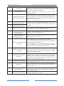
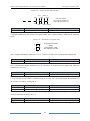
Thermal
protection relay
The output side of
frequency inverter
Although the inverter has motor overload protection function, when
one inverter drives two or more motors or multi-pole motors, to
prevent the motor over-temperature failure, thermal protection relay
shall be installed between the inverter and each motor.
Output filter
The output side of
frequency inverter
When the output side of the inverter is connected with output filter,
the conduction and radiation interference can be reduced.
Output AC
reactor
Between the
output side of
frequency inverter
and motor, near
the frequency
inverter
When the cable connecting the inverter and the motor is longer than
100meters, it is suggested to install AC output reactor to suppress the
high-frequency oscillation to avoid the damage to motor insulation,
large leakage current and frequent inverter protective action.
Contactor
20
KOC100 Series High Performance Vector Control User Manual
Installation of AC drive
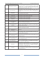
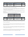
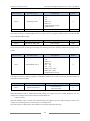
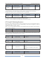
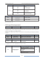
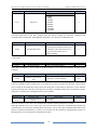
3.5 Model Selection of Main Circuit Peripheral Devices
Table 3-2
Frequency inverter
Model
Model Selection Diagram of Main Circuit Peripheral Devices (Recommended)
MCCB
(A)
Contactor
(A)
Cable of Input Side
Main Circuit
(mm2)
Cable of Output
Side Main Circuit
(mm2)
Cable of
Control Circuit
(mm2)
Single-phase 220V
KOC100-0R4S2
16
10
2.5
2.5
1.0
KOC100-R75S2
16
10
2.5
2.5
1.0
KOC100-1R5S2
20
16
4.0
2.5
1.0
Three-phase 380V
KOC100-0R4T4
10
10
2.5
2.5
1.0
KOC100-R75T4
10
10
2.5
2.5
1.0
KOC100-1R5T4
16
10
2.5
2.5
1.0
KOC100-2R2T4
16
10
2.5
2.5
1.0
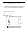
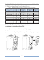
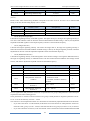
3.6 Removal and mounting of operating panel and cover
3.6.1 Removal and mounting of operating panel (keypad)
The operating panel of KOC100 series Frequency inverter is a plug type, If you need to take it off when use or
maintenance, please make sure the gentle actions, or it is easy to damage the plug type connection terminals on
operating panel.
The removal and mounting of operating panel (keypad) is showed as Figure3-3 and Figure3-4:
Figure 3-3
Removal of operating panel (keypad)
Figure 3-4
21
Mounting of operating panel (keypad)
Installation of AC drive
KOC100 Series High Performance Vector Control User Manual
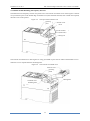
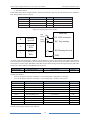
3.6.2 Removal and Mounting of Frequency Inverter
The KOC100 series frequency inverter uses plastic case. The removal of terminal cover refers Figure3-5. Please
use your hand to press on the bottom edge of terminal cover(near the hook terminal) with a small force upward,
then the cover can be opened.
Figure 3-5
The open of the terminal cover
Operating
panel
Terminal cover
Hook
Open the terminal
cover (Removable)
Cabling hole
The removal of terminal cover refers figure3-6. Using your thumb to press the two sides of the terminal cover to
make the cover to separate from the mounting holes.
Figure 3-6
The removal of terminal cover
Terminal cover
Operating
panel
Cabling hole
Terminal cover
mounting hole
22
KOC100 Series High Performance Vector Control User Manual
Installation of AC drive
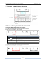
3.7 Connection Terminals Diagram Description
Figure 3-7
KOC100 Series Terminal Distribution Diagram
Control Circuit
Terminals
Grounding
Main Circuit
Terminals
Terminals
3.8 Sketch and Description of Main Circuit Terminals
3.8.1 Function and description of Main Circuit Terminals
3.8.1.1 Main Circuit Terminals Sketch of Single-phase 220V KOC100 Series
Including model: KOC100-0R4S2~KOC100-1R5S2
Terminal symbol
Terminal name and function description
P+、PB
Connecting terminals of braking resistor
/E
Grounding terminal
L, N
Single-phase AC power input terminals
U, V, W
Three-phase AC power output terminals
3.8.1.2 Main Circuit Terminals Sketch of Three-phase 380V KOC100 Series
Including model: KOC100-0R4T4~KOC100-2R2T4
Terminal symbol
Terminal name and function description
P+、PB
Connecting terminals of braking resistor
23
Installation of AC drive
KOC100 Series High Performance Vector Control User Manual
Grounding terminal
/E
R, S, T
Three-phase AC power input terminals
U, V, W
Three-phase AC power output terminals
3.9 Cautions for Main Circuit Wiring
3.9.1 Power Supply Wiring
◆It is forbidden to connect the power cable to the inverter output terminal, otherwise, the internal components
of the inverter will be damaged.
◆To facilitate the input side over current protection and maintenance after power off, the inverter shall connect
to the power supply through the circuit breaker or leakage circuit breaker and contactor.
◆Please confirm that the power supply phases, rated voltage are consistent with that of the nameplate, otherwise,
the inverter may be damaged.
3.9.2 Motor Wiring
◆It is forbidden to short circuit or ground the inverter output terminal, otherwise the internal components of the
inverter will be damaged.
◆Avoid short circuit the output cables or with the inverter enclosure, otherwise there exists the danger of
electric shock.
◆It is forbidden to connect the output terminal of the inverter to the capacitor or LC/RC noise filter with phase
lead, otherwise, the internal components of the inverter may be damaged.
◆When contactor is installed between the inverter and the motor, it is forbidden to switch on/off the contactor
during the running of the inverter, otherwise, there will be large current flowing into the inverter, triggering
the inverter protection action.
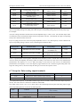
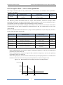
◆Length of cable between the inverter and motor
If the cable between the inverter and the motor is too long, the higher harmonic leakage current of the output
end will produce by adverse impact on the inverter and the peripheral devices. It is suggested that when the
motor cable is longer than 100m, output AC reactor be installed. Refer to the following table for the carrier
frequency setting.
Table 3-3
Length of cable between
the inverter and motor
Carrier frequency (d6-00)
Comparison table between the cable length and carrier frequency
Less than 50m
Less than 100 m
More than 100m
Less than 15kHz
Less than 10kHz
Less than 5kHz
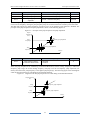
3.9.3 Grounding Wiring
◆The inverter will produce leakage current. The higher the carrier frequency is, the larger the leakage current
will be. The leakage current of the inverter system is more than 3.5mA, and the specific value of the leakage
current is determined by the use conditions. To ensure the safety, the inverter and the motor must be grounded.
◆The grounding resistance shall be less than 10ohm. For the grounding wire diameter requirement, refer to 2.6
electrotype of main circuit peripheral devices.
◆Do not share grounding wire with the welding machine and other power equipment.
In the applications with more than 2 inverters, keep the grounding wire from forming a loop.
24
KOC100 Series High Performance Vector Control User Manual
Figure 3-8
Installation of AC drive
Grounding Wire Connection Sketch Map
Correct
Wrong
3.9.4 Countermeasures for Conduction and Radiation Interference
Figure 3-9
Connection of conduction and radiation interference solutions
◆When the noise filter is installed, the wire connecting the filter to the inverter input power end shall be as short
as possible.
◆The filter enclosure and mounting cabinet shall be reliably grounded in large area to reduce the back flow
impedance of the noise current Ig.
◆The wire connecting the inverter and the motor shall be as short as possible. The motor cable adopts 4-core
cable, with the grounding end grounded at the inverter side, the other end connected to the motor enclosure. The
motor cable shall be sleeved into the metal tube.
◆The input power wire and output motor wire shall be kept away from each other as far as possible.
◆The equipment and signal cables vulnerable to influence shall be kept far away from the inverter.
◆Key signal cables shall adopt shielding cable. It is suggested that the shielding layer shall be grounded with
360-degree grounding method and sleeved into the metal tube. The signal cable shall be kept far away from the
inverter input wire and output motor wire. If the signal cable must cross the input wire and output motor wire,
they shall be kept orthogonal.
◆When analog voltage and current signals are adopted for remote frequency setting, twinning shielding cable
shall be used. The shielding layer shall be connected to the grounding terminal PE of the inverter, and the signal
cable shall be no longer than 50m.
◆The wires of the control circuit terminals RA/RB/RC and other control circuit terminals shall be separately
routed.
◆It is forbidden to short circuit the shielding layer and other signal cables and the equipment.
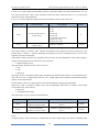
◆When the inverter is connected to the inductive load equipment (e.g. electromagnetic contactor, relay and
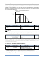
solenoid valve), surge suppressor must be installed on the load equipment coil, as showed in Figure 3-10.
25
Installation of AC drive
KOC100 Series High Performance Vector Control User Manual
Inductive
感性
load
负载
Application example of inductive load surge suppressor
Piezoresistor
Figure 3-10
感性
DC 24V Inductive
load
负载
压敏
电阻
AC 220V
感性
Inductive
load
负载
AC 220V
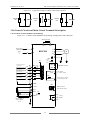
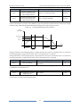
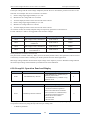
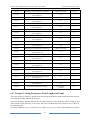
3.10 Control Circuit and Main Circuit Terminals Description
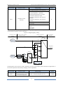
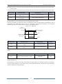
3.10.1 Control Circuit and Main Circuit Wiring
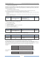
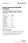
Figure 3-11 Control Circuit and Main Circuit Wiring of Single-phase 220V KOC100
Braking Resistor
(P+)
Single-phase
220V input
power
~
PB
L
U
KOC100
N
M
V
W
S3
To match
with
ON OFF
resistor
+5V
Multi-functional digital
input terminal 1
DI1 Default
Multi-functional digital
input terminal 2
DI2 asDefault
REV
Multi-functional digital
input terminal 3
DI3
Multi-functional digital
input terminal 4
DI4
Multi-functional digital
input terminal 5
DI5
485+
as FWD
AO1
AO1 output:
0~10V/0~20mA
GND
Select AO1 as voltage
or current type by S2
S2
I
GND
V
DO
+10V
Multi-functional
open collector output
AI1
Analog input
0~10V/0~20mA
GND
S1
AI2
GND
MODBUS interface
485-
I
V
TA
TB
TC
Select voltage or
current giving
by S1
26
Relay
output 1
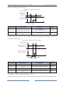
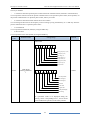
KOC100 Series High Performance Vector Control User Manual
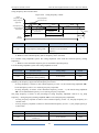
Figure 3-12
Installation of AC drive
Control Circuit and Main Circuit Wiring of Three-phase 380V KOC100
Braking Resistor
(P+)
PB
R
Three-phase
380V input
power
U
KOC100
S
~
M
V
W
T
S3
To match
with
ON OFF
resistor
+5V
Multi-functional digital
input terminal 1
DI1 Default
Multi-functional digital
input terminal 2
DI2 asDefault
REV
Multi-functional digital
input terminal 3
DI3
Multi-functional digital
input terminal 4
DI4
Multi-functional digital
input terminal 5
DI5
485+
as FWD
AO1
AO1 output:
0~10V/0~20mA
GND
Select AO1 as voltage
or current type by S2
S2
I
GND
V
DO
+10V
Multi-functional
open collector output
AI1
Analog input
0~10V/0~20mA
MODBUS interface
485-
AI2
GND
GND
S1
I
V
TA
TB
TC
Select voltage or
current giving
by S1
Relay
output 1
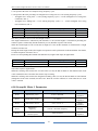
3.10.2 Control Circuit Terminal Layout
Figure 3-13
KOC100 Control Circuit Terminal Sketch Map
27
Installation of AC drive
KOC100 Series High Performance Vector Control User Manual
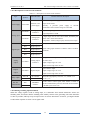
3.10.3 Description of control circuit terminals
Table 3-4
Type
Terminal
Symbol
Description of control circuit terminals
Terminal Name
Terminal function description
Provide +10V power supply to external unit. Maximum
Power Supply
+10V-GND
External +10V
output current:10mA
power supply
Generally,
it
provides
power
supply
to
external
potentiometer with resistance range of 1 kΩ~5kΩ
AI1-GND
Analog input
terminal 1
Analog input
AI2-GND
Digital input
Analog input
terminal 2
DI1
Digital input 1
DI2
Digital input 2
DI3
Digital input 3
DI4
Digital input 4
DI5
Digital input 5
1. Input voltage range: DC 0V~10 V
2. Input Impedance: 22 kΩ
1. Input range: DC 0V~10V/ 0mA~20mA, decided by the
switch ‖AI2‖ on the control board
2. Impedance: 22 kΩ (voltage input), 500 Ω (current input)
Digital analog input terminals is effective when it connects
with GND.
Voltage or current output is decided by the switch ‖AO‖ on
Analog
output
AO-GND
Analog output
terminal 1
the control card.
Output voltage range: 0V~10 V
Output current range: 0mA~20 mA
Digital
output
Relay output
RS-485
communication
Open-collector output
DO-GND
Digital output 1
Output voltage range: 0V~24 V
Output current range: 0mA~50 mA
T/A-T/B
NC terminal
Contact driving capacity: 250 VAC, 3 A, COSØ = 0.4
T/A-T/C
NO terminal
DC 30 V, 1 A
485+
MODBUS
485-
interface
Provide remote control signal, Data format is based on
RS-485 communication protocol, the break off of resistance
is decided by the switch ‖S3‖.
3.10.4 Wiring of Analog Input Terminals
When the voltage signal is used as analog input, it is vulnerable from outside interference. Please use
shielding cable, and ensure that the shielding cable reliably connect to the grounding. The cable should be
as short as possible, and keep away from power lines. In serious interference occasions, you might consider
to add a filter capacitor or ferrite core in signal cable.
28
KOC100 Series High Performance Vector Control User Manual
Figure 3-14
Installation of AC drive
Wiring of analog input terminals
3.10.5 Wiring of Multi-functional Input Terminals
Figure 3-15
Wiring of digital input terminals
5V
DI1
DI2
DI3
DI4
KOC100
DI5
GND
Single-end of shied
cable grounding
3.10.6 Wiring of digital output terminals when using external power supply
Relay
KOC100
DO1
+
External
power supply
20~28V
GND
External Power Supply Wiring
29
Installation of AC drive
KOC100 Series High Performance Vector Control User Manual
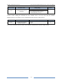
3.10.7 Description of Control Circuit Jumper
Jumper Name
Function Description
Default Setting
When the jumper is ―ON‖, it connects with 485 communication resistor.
S3
When the jumper is ―OFF‖, it disconnects with 485 communication
OFF
resistor
AI2
AO
When the jumper is ―V‖, AI2 is with voltage input (0~10V).
When the jumper is ―I‖, AI2 is with current input (0~20mA).
When the jumper is ―V‖, AO is with voltage output (0~10V).
When the jumper is ―I‖, AO is with current output (0~20mA).
30
V
V
KOC100 Series High Performance Vector Control User Manual
Operation and display
Chapter 4 Operation and display
4.1 Instruction of operation and display
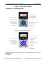
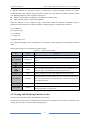
Figure 4-1
Operating panel
Digital tube display
Current state indicator
Frequency indicator
Voltage state indicator
Increasing key
Control mode indicator
Fault alarm indicator
Reversal indicator
Data key/Confirmation key
Forward indicator
Shift Key
Menu/Exit key
Running key
Stop/Reset key
Decreasing key
Figure 4-2
Operating panel(With potentiometer)
Digital tube display
Current state indicator
Frequency indicator
Voltage state indicator
Increasing key
Control mode indicator
Fault alam indicatior
Reversal indicator
Forward indicator
Potentiometer
Data key/Confirmation key
Menu/Exit key
Shift Key
Stop/Reset key
Running key
Decreasing key
1) Description of indicator
RUN:
OFF indicates that the frequency inverter is in the stop state and ON indicates that the frequency inverter is
in the running state.
REMOTE:
31
Operation and display
KOC100 Series High Performance Vector Control User Manual
It indicates whether the frequency inverter is operated by operation keypad, terminals or remoter
(communication). OFF indicates keypad operation control state; ON indicates terminals operation control
state; Blinking indicates remote operation control state.
DIR: It is Forward/Reversal indicator, ON indicates forward rotation.
TRIP: Tunning/ Torque Control/Fault indicator
When the indicator is ON, it indicates torque control mode. When the indicator is blinking slowly, it
indicates the auto-tuning state. When the indicator is blinking quickly, it indicates the fault state.
2) Unit indicator
Hz: frequency unit;
A: Current unit;
V: Voltage unit
3) Digital display area
The 5-digit LED display is able to display the set frequency, output frequency, monitoring data and fault
codes.
4) Description of Keys on the Operation panel (keypad)
Table 4-1
Key
Name
PRG/ESC
Programming
DATA/ENTER
Confirmation
Function
Enter or exit menu level I.
Enter the menu interfaces level by level, and confirm the parameter
setting.
Increment
Increase data or function code.
Decrement
Decrease data or function code.
Shift
RUN
Keypad function table
RUN
Select the displayed parameters in turn in the stop or running state, and
select the digit to be modified when modifying parameters.
Start the frequency inverter in the operation panel control mode.
Stop the frequency inverter when it is in the running state and perform
STOP/RESET
Stop/Reset
the reset operation when it is in the fault state. The functions of this key
are restricted by b9-00.
PRG+ENTER
MF.K
DATA+PRG
QUICK
Perform function switchover according to the setting of b9-01
Perform switchover between menu modes according to the setting of
A0-08(The default is a menu mode).
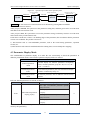
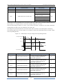
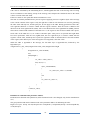
4.2 Viewing and Modifying Function Codes
The operation panel of the KOC100 adopts three-level menu.
The three-level menu consists of function code group (Level I), function code (Level II), and function code
setting value (level III), as shown in the following figure.
32
KOC100 Series High Performance Vector Control User Manual
Figure 4-3
PRG/ESC
Operation procedure on the operation panel
Change parameter
group
50.00
Operation and display
ENTER
Change functional
code
b0
b0-08
PRG/ESC
Level 0 menu
PRG/ESC
Level I menu
Level II menu
ENTER
Change the value of
functional code
050.00
PRG/ESC
ENTER Level III menu
Instruction: We can return to level II menu from Level III menu by pressing PRG or ENTER.
The difference between them is:
After you press ENTER, the system saves the parameter setting first, and then goes back to Level II menu
and shifts to the next function code.
After you press PRG, the system does not save the parameter setting, but directly returns to Level II menu
and remains at the present function code.
Under the Level III state, if there is no blinking digit of this parameter, then it indicates that the parameter
can not to be modified. The possible reasons are:
1) This function code is a non-modifiable parameter, such as the actual testing parameters, operation
records, etc.
2) This function code cannot be modified under the running state, but can modify after stopping.
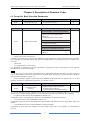
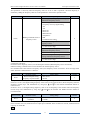
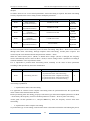
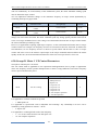
4.3 Parameter Display Mode
The establishment of parameter display is to make the user conveniently to check the parameters in
different permutation modes. Three kinds of parameter display modes are offered.
Name
Function parameter
mode
Customized parameter
mode
Modifiable parameter
mode
Description
sequential display the function parameters of frequency
inverter, includes parameter group b0~bF, C0~C6, d0~
d6, A0~A1 and U0
Several function parameters (max 32) customized to display
are need to confirmed by Group A1
The function parameters can be different with the factory
parameter
Relevant function parameters are A0-08, as follows:
Function Code
Parameter Name
Setting Range
Default
Unit's digit (User-defined parameter QUICK
display selection)
0: Not display
A0-08
Individualized parameter
display property
1: Display
0
Ten's digit (User-modified parameter QUICK
display selection)
0: Not display
1: Display
When user defined customized parameters, at this time user can switch into different parameter display
mode by the QUICK key.
33
Operation and display
KOC100 Series High Performance Vector Control User Manual
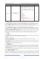
All parameter display mode display the code as follows:
Parameter Display Mode
Display
Base mode
-dFLt
User-defined mode
-user
User-modified mode
-chGd
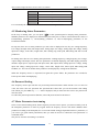
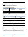
Switching mode is as follows:
The following diagram shows change the current basic mode to user-defined mode.
Figure 4-4
Quick viewing mode of function codes
QUICK
Status parameters
(Default display)
Basic mode
(All function codes)
QUICK
50.00
User-defined mode
(Only for Group A1)
QUICK
-dFLt
ENTER
ENTER
cb0.10
ub0.08
cb0.21
d0
……
ub0.03
……
b0
……
The right side is
only example of
function codes.
User can modify
the code
according
to your need.
-chGd
A0-08 = 1x
ENTER
Level I menu
QUICK
-user
A0-08 = x1
No key operation
within 2 seconds
User-modified mode
(Modified function codes)
ub4.00
ub0.00
U0
4.4 Operation Mode of User-defined Parameters
User-defined menu is set to facilitate user to quickly view and modify the commonly used function codes.
In this mode, the display parameter ―ub0.02‖ is function code ―b0-02‖. User also can modify parameters
value in this menu, the effect is same as modifying in common menu.
The user-defined parameters set by group A1. If A1 is set to A0.00, it indicates that no function codes are
available. The max 32 parameters can be defined in group A1. If "NULL" is displayed, it indicates that the
user-defined menu is empty.
A total of 16 parameters are pre-stored in the user-defined fast menu, as listed in the following table.
b0-01
control mode
b0-02
Command source selection
b0-03
Main frequency source X selection
b0-07
Frequency source selection
b0-12
Preset frequency
b0-21
Acceleration time
b0-22
b3-00
Deceleration time
DI1 function selection
b3-01
DI2 function selection
b3-02
DI3 function selection
b4-04
DO output selection
34
KOC100 Series High Performance Vector Control User Manual
Operation and display
b6-01
AO output selection
b1-00
Start mode
b1-10
d2-00
Stop mode
V/F curve setting
d2-01
Torque boost
User can modify the user-defined fast menu based on actual requirements.
4.5 Monitoring Status Parameters
In the stop or running state, you can press ―
” on the operation panel to display status parameters.
Whether parameters are displayed is determined by the binary bits of values converted from the values of
b9-02(running parameter 1), b9-03(running parameter 2), and b9-04(stopping parameter) in the
hexadecimal format.
In stop state, there are 16 status parameters you can select to displayed or not, they are: setting frequency,
bus voltage, DI input status, DO output status, analog input AI1 voltage, analog input AI2 voltage, analog
input AI3 voltage, count value, length value, PLC running step, load speed, PID setting and four reserved
parameters.
In running state, there are five running state parameters: running frequency, setting frequency, bus voltage,
output voltage and output current. This five parameters are default displaying. The other display parameter
includes output power, output torque, DI input status, DO output status, analog input AI1 voltage, analog
input AI2 voltage, analog input AI3 voltage, count value, length value, linear speed, PID setting, PID
feedback, etc. You can set whether these parameters are displayed by setting b9-02 and b9-03.
When the frequency inverter is repowered on again after power failure, the parameters are recorded as
before power failure and displaying.
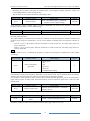
4.6 Password Setting
The frequency inverter provides the user password protection function. When A0-00 is set to a non-zero
value, the value is the user password. The password takes effect after you exit the function code editing
state. When you press PRG key, ―------‖ will be displayed, and you must enter the correct user password to
enter the menu.
To cancel the password protection function, enter with password and set A0-00 to 0.
4.7 Motor Parameter Auto-tuning
Select vector control running mode, before frequency inverter start to operate, you must accurately write in
the nameplate parameter of motor by keypad. KOC100 frequency inverter will match standard motor
parameter according to the nameplate; the vector control mode strongly depended on motor’s parameters, if
you want to get good control performance, then you must let inverter to obtain the exact parameters of
controlled motor.
The process of motor auto-tuning is as follows:
35
Operation and display
KOC100 Series High Performance Vector Control User Manual
Firstly, select command source(b0-02) as keypad command channel. Then write in the actual motor
parameters as the following parameters (according to the nameplate of present motor):
Motor
Motor 1
Motor 2
Parameter
b0-00:Motor Type Selection
d0-00:Motor Rated Power
d0-01:Motor Rated Voltage
d0-02:Motor Rated Current
d0-03:Motor Rated Frequency
d0-04:Motor Rated Speed
b0-00:Motor Type Selection
d2-00:Motor Rated Power
d2-01:Motor Rated Voltage
d2-02:Motor Rated Current
d2-03:Motor Rated Frequency
d2-04:Motor Rated Speed
AC asynchronous motor tuning
If the motor can be disconnected from the load, then please set d0-30/d3-30 to 2(asynchronous motor
complete auto-tuning), then press the RUN key on the keypad. The frequency inverter will automatically
calculate the following parameters of motor:
Motor
Parameter
d0-05:Stator resistance (asynchronous motor)
d0-06:Rotor resistance (asynchronous motor)
Motor 1
d0-07:Leakage inductive reactance(asynchronous motor)
d0-08:Mutual inductive reactance(asynchronous motor)
d0-09:No-load current(asynchronous motor)
d2-05:Stator resistance (asynchronous motor)
d2-06:Rotor resistance (asynchronous motor)
Motor 2
d2-07:Leakage inductive reactance(asynchronous motor)
d2-08:Mutual inductive reactance(asynchronous motor)
d2-09:No-load current(asynchronous motor)
Finish motor parameter auto-tuning.
If the motor cannot be fully disconnected with the load, then please select d0-30/d3-30 as 1 (asynchronous
static auto-tuning), and press the RUN key in the keypad panel.
And the frequency inverter will automatically calculate the following parameters of motor:
Motor
Parameter
d0-05:Stator resistance (asynchronous motor)
Motor 1
d0-06:Rotor resistance (asynchronous motor)
d0-07:Leakage inductive reactance(asynchronous motor)
d2-05:Stator resistance (asynchronous motor)
Motor 2
d2-06:Rotor resistance (asynchronous motor)
d2-07:Leakage inductive reactance(asynchronous motor)
36
KOC100 Series High Performance Vector Control User Manual
Function Code Table
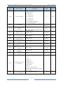
Chapter 5 Function Code Table
If A0-00 is set to a non-zero number, parameter protection is enabled. You must enter correct user password
to enter the menu.
To cancel the password protection function, enter with password and set A0-00 to 0.
The user defined fast menu can directly enter without password.
Group A is frequency inverter system parameter. Group b is basic function parameters. Group C is
application parameter, Group d is control parameter, and Group U is monitoring function parameters.
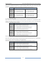
The symbols in the function code table are described as follows:
"☆": The parameter can be modified when the frequency inverter is in stop or running state.
"★": The parameter cannot be modified when the frequency inverter is in running state.
"●": The parameter is the actually measured value and cannot be modified.
"*": The parameter is factory parameter and can be modified only by the manufacturer.
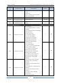
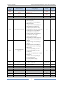
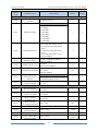
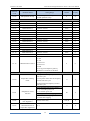
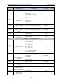
Standard Function Parameters
Function
Code
b0-00
b0-01
b0-02
b0-03
Parameter Name
Setting Range
Group b0: Basic Function Parameters
Unit’s digit (Motor 1 selection)
Motor type selection
0: AC asynchronous motor
Unit's digit (Motor 1 control mode
selection)
0: Sensor-less vector control (SVC)
1: Reserved
2: Voltage/Frequency (V/F) control
Ten's digit (Motor 2 control mode
selection)
Motor control mode
0-1(same as unit’s digit)
Hundred’s digit/Thousand’s digit:
reserved
Ten thousand’s digit(Motor selection)
0: Motor 1
1: Motor 2
0: keypad control (LED off)
Command source
1: Terminal control (LED on)
selection
2: Communication control (LED
blinking)
0: Digital setting (Preset frequency
b0-12, UP/DOWN modifiable,
no-record after power off)
1: Digital setting (Preset frequency
b0-12, UP/DOWN modifiable, record
Main frequency source
after power off)
X selection
2: AI1
3: AI2
4: Reserved
5: Reserved
6: Multi-function
37
Default
Property
0
★
0
★
0
0
★
★
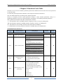
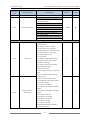
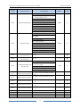
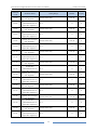
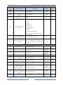
Function Code Table
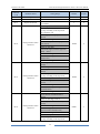
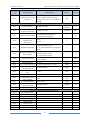
Function
Code
b0-04
b0-05
b0-06
KOC100 Series High Performance Vector Control User Manual
Parameter Name
Auxiliary frequency
source Y selection
Selection range of
auxiliary frequency Y
Range of auxiliary
frequency Y
Setting Range
7: Built-in PLC
8: PID
9: Communication setting
10: AI-KB (Potentiometer Keypad)
The same as b0-03 (Main frequency
source X selection)
0: Relative to maximum frequency
1: Relative to main frequency X
0%~150%
Default
Property
1
★
0
☆
100%
☆
0
☆
b0-07
Frequency source
selection
Unit's digit (Frequency source
selection)
0: Main frequency source X
1: X and Y calculation (calculation
result determined by ten's digit)
2: Switchover between X and Y
3: Switchover between X and "X and Y
calculation"
4: Switchover between Y and "X and Y
calculation"
Ten's digit (X and Y calculation
relationship)
0: X+Y
1: X-Y
2: Maximum of them
3: Minimum of them
b0-08
Frequency offset of
auxiliary frequency
source of X and Y
0.00 Hz ~ maximum frequency(b0-13)
0.00 Hz
☆
Binding command
source to frequency
source
Unit's digit (Binding keypad command
to following frequency source)
0: No binding
1: Frequency source by digital setting
2: AI1
3: AI2
4: Reserved
5: Reserved
6: Multi-function
7: Simple PLC
8: PID
9: Communication setting
Ten's digit (Binding terminal
command to frequency source)
0~9, same as unit's digit
Hundred's digit (Binding
communication command to frequency
source)
0
☆
b0-09
38
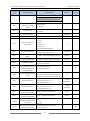
KOC100 Series High Performance Vector Control User Manual
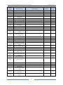
Function
Code
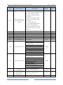
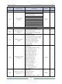
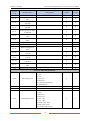
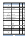
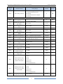
Function Code Table
Default
Property
0: Not record
1: Record
1
☆
1: 0.1 Hz
2: 0.01 Hz
2
☆
0.00 ~ maximum frequency (b0-13)
50.00 Hz
☆
50.00~3000.0 Hz
50.00 Hz
☆
0
☆
50.00 Hz
☆
Parameter Name
Setting Range
0~9, same as unit's digit
Thousand’s digit (Automatically
running binding to frequency source)
0~9, same as unit's digit
b0-10
Record of digital setting
frequency of power
failure
b0-11
Frequency unit
b0-12
Preset frequency
b0-13
Maximum frequency
0: Set by b0-15
1: AI1
2: AI2
3: Reserved
4: Reserved
5: Communication setting
Frequency lower limit (b0-17) ~
maximum frequency (b0-13)
b0-14
Source of frequency
upper limit
b0-15
Frequency upper limit
b0-16
Frequency upper limit
offset
0.00 Hz~ maximum frequency(b0-13)
0.00 Hz
☆
b0-17
Frequency lower limit
0.00 Hz ~frequency upper limit(b0-15)
0.00 Hz
☆
b0-18
Rotation direction
0: Forward direction
1: Reverse direction
0
☆
b0-19
Base frequency for UP/
DOWN modification
during running
0: Running frequency
1: Setting frequency
0
★
b0-20
Acceleration/Deceleratio
n mode
0
☆
b0-21
Acceleration time 1
Model
dependent
☆
b0-22
Deceleration time 1
Model
dependent
☆
b0-23
Time proportion of
S-curve start segment
0.0% ~ (100.0% minus b0-24)
30.0%
☆
b0-24
Time proportion of
S-curve end segment
0.0% ~ (100.0% minus b0-23)
30.0%
☆
b0-25
Acceleration/Deceleratio
n time unit
0:1s
1: 0.1s
2: 0.01s
1
☆
b0-26
Acceleration/Deceleratio
n time base frequency
0: Maximum frequency (b0-13)
1: Set frequency
0
★
0: Linear acceleration/ deceleration
1: S-curve acceleration/deceleration A
2: S-curve acceleration/deceleration B
0.00s~650.00s (b0-25 = 2)
0.0s~6500.0s (b0-25 = 1)
0s~65000s (b0-25 = 0)
0.00s~650.00s (b0-25 = 2)
0.0s~6500.0s (b0-25 = 1)
0s~65000s (b0-25 = 0)
39
Function Code Table
Function
Code
b1-00
KOC100 Series High Performance Vector Control User Manual
Parameter Name
Setting Range
2: 100 Hz
Group b1: Start and Stop Control Parameters
0: Direct start
1: Rotational speed tracking restart
Start mode
2: Pre-excited start (asynchronous
motor)
Default
Property
0
★
b1-01
Rotational speed
tracking mode
0: From frequency at stop
1: From zero speed
2: From maximum frequency
0
★
b1-02
Rotational speed
tracking speed
1~100
20
★
b1-03
Startup frequency
0.00~10.00 Hz
0.00 Hz
☆
b1-04
Startup frequency
holding time
0.0s~100.0s
0.0s
★
b1-05
Startup DC braking
current/ Pre-excited
current
0%~100%
0%
★
b1-06
Startup DC braking
time/ Pre-excited time
0.0s~100.0s
0.0s
★
b1-07
Stop mode
0
☆
b1-08
DC braking initial
frequency of stopping
0.00 Hz
☆
b1-09
DC braking waiting
time of stopping
0.0s~100.0s
0.0s
★
b1-10
DC braking current of
stopping
0%~100%
0%
★
b1-11
DC braking time of
stopping
0.0s~100.0s
0.0s
★
6.00 Hz
☆
0: Decelerate to stop
1: free stop
0.00 Hz ~ maximum frequency
Group b2: Auxiliary Function
b2-00
JOG running frequency
0.00 Hz ~ maximum frequency
b2-01
JOG acceleration time
0.0s~6500.0s
Model
dependent
☆
b2-02
JOG deceleration time
0.0s~6500.0s
Model
dependent
☆
b2-03
Acceleration time 2
0.0s~6500.0s
Model
dependent
☆
b2-04
Deceleration time 2
0.0s~6500.0s
Model
dependent
☆
b2-05
Acceleration time 3
0.0s~6500.0s
Model
dependent
☆
b2-06
Deceleration time 3
0.0s~6500.0s
Model
dependent
☆
40
KOC100 Series High Performance Vector Control User Manual
Function
Code
Parameter Name
b2-07
Acceleration time 4
b2-08
Deceleration time 4
b2-09
Jump frequency 1
b2-10
Function Code Table
Default
Property
0.0s~6500.0s
Model
dependent
☆
0.0s~6500.0s
Model
dependent
☆
0.00 Hz ~maximum frequency
0.00 Hz
☆
Jump frequency 2
0.00 Hz ~ maximum frequency
0.00 Hz
☆
b2-11
Frequency jump
amplitude
0.00 Hz ~ maximum frequency
0.00 Hz
☆
b2-12
Jump frequency during
acceleration/deceleration
0
☆
b2-13
Frequency switchover
point between
acceleration time 1 and
acceleration time 2
0.00 Hz ~ maximum frequency
0.00 Hz
☆
b2-14
Frequency switchover
point between
deceleration time 1 and
deceleration time 2
0.00 ~ maximum frequency
0.00 Hz
☆
b2-15
Reverse running
0: Enabled
1: Disabled
0
☆
b2-16
Forward/Reverse
rotation dead-zone time
0.0~3000.0s
0.0s
☆
b2-17
Running mode when set
frequency lower than
frequency lower limit
0: Run at frequency lower limit
1: Stop
2: Run at zero speed
0
☆
b2-18
Droop control
0.00 Hz
☆
b2-19
Terminal JOG priority
0: Disabled
1: Enabled
0
☆
b2-20
Accumulative power-on
time reach threshold
0~65000 h
0h
☆
b2-21
Accumulative running
time reach threshold
0~65000 h
0h
☆
b2-22
Action after running
time reached
0: Continue to run
1: Stop
0
☆
b2-23
Cooling fan control
0: Fan working during running
1: Fan working during power on
0
☆
b2-24
Dormant frequency
0.00Hz ~wakeup frequency (b2-26)
b2-25
Dormant delay time
0.0s~6000.0s
b2-26
Wakeup frequency
Dormant frequency (b2-24)~ maximum
frequency (b0-13)
b2-27
Wakeup delay time
0.0s~6000.0s
b2-28
Timing function
b2-29
Timing duration source
Setting Range
0: Disabled
1: Enabled
0.00Hz~10.00 Hz
0: Disabled
1: Enabled
0: b2-30
41
0.00 Hz
☆
0.0s
☆
0.00 Hz
☆
0.0s
☆
0
☆
0
☆
Function Code Table
Function
Code
KOC100 Series High Performance Vector Control User Manual
Parameter Name
Setting Range
Default
Property
1: AI1
2: AI2
3: Reserved
(100% of analog input corresponds
to the value of b2-30)
b2-30
Timing duration
0.0min~6500.0 min
0.0 min
☆
b2-31
This time running time
reached threshold
0.0min~6500.0 min
0.0 min
☆
b2-32
Startup protection
0: No
1: Yes
Group b3: Switch Input Terminal Parameters
b3-00
DI1 function selection
b3-01
DI2 function selection
b3-02
DI3 function selection
0: No function
1: Forward RUN (FWD) or running
command
2: Reverse RUN (REV) or FWD/REV
running direction
3: Three-line control
4: Forward JOG (FJOG)
5: Reverse JOG (RJOG)
6: Multi-function terminal 1
7: Multi-function terminal 2
8: Multi-function terminal 3
9: Multi-function terminal 4
10: Terminal UP
11: Terminal DOWN
12: clear to zero of UP and DOWN
setting (terminal, keypad)
13: Terminal 1 for acceleration/
deceleration time selection
14: Terminal 2 for acceleration/
deceleration time selection
15: Frequency source switchover
16: Switchover between main
frequency source X and preset
frequency
17: Switchover between auxiliary
frequency source Y and preset
frequency
18:Terminal 1 for Command source
switchover
19: Terminal 2 for Command source
switchover
20: Speed control/Torque control
switchover
21: Torque control prohibited
22: PID pause
23: PID integral pause
42
0
☆
1
★
6
★
7
★
KOC100 Series High Performance Vector Control User Manual
Function
Code
Parameter Name
Function Code Table
Setting Range
24: Reverse PID action direction
25: PID parameter switchover
26: PLC status reset
27: Swing pause
28: Counter input
29: Counter reset
30: Length count input
31: Length reset
32: Reserved
33: Frequency modification enable
34:Acceleration/Deceleration prohibited
35: Motor selection terminal 1
36: Motor selection terminal
2(reserved)
37: Fault reset
38: Normally open (NO) input of
external fault
39: Normally closed (NC) input of
external fault
40: User-defined fault 1
41: User-defined fault 2
42: Running pause
43: Free stop
44: Emergency stop
45: External STOP terminal 1
46: External STOP terminal 2
47: Deceleration DC braking
48: Immediate DC braking
49: Clear the current running time
Default
Property
8
★
9
★
0.010s
☆
0
★
1.000 Hz/s
☆
b3-03
DI4 function selection
b3-04
DI5 function selection
b3-12
DI filter time
b3-13
Terminal command
mode
b3-14
Terminal UP/DOWN
rate
b3-15
DI1 ON delay time
0.0s~3000.0s
0.0s
☆
b3-16
DI1 OFF delay time
0.0s~3000.0s
0.0s
☆
b3-17
DI2 ON delay time
0.0s~3000.0s
0.0s
☆
b3-18
DI2 OFF delay time
0.0s~3000.0s
0.0s
☆
b3-19
DI3 ON delay time
0.0s~3000.0s
0.0s
☆
b3-20
DI3 OFF delay time
0.0s~3000.0s
0.0s
☆
b3-21
DI4 ON delay time
0.0s~3000.0s
0.0s
☆
b3-22
DI4 OFF delay time
0.0s~3000.0s
0.0s
☆
b3-23
DI5 ON delay time
0.0s~3000.0s
0.0s
☆
0.000s~1.000s
0: Two-line mode 1
1: Two-line mode 2
2: Three-line mode 1
3: Three-line mode 2
0.001Hz/s~65.535 Hz/s
43
Function Code Table
KOC100 Series High Performance Vector Control User Manual
Function
Code
Parameter Name
b3-24
DI5 OFF delay time
b3-25
b4-01
b4-02
Setting Range
0.0s~3000.0s
Unit's digit (DI1 valid mode)
0: Low level valid
1: High level valid
Ten's digit (DI2 valid mode)
0, 1 (same as DI1)
Hundred's digit (DI3 valid mode)
DI valid selection 1
0, 1 (same as DI1)
Thousand's digit (DI4 valid mode)
0, 1 (same as DI1)
Ten thousand's digit (DI5 valid mode)
0, 1 (same as DI1)
Group b4: Switch Signal output Terminals
0: No output
1: Ready signal
2: Frequency inverter running
3: Fault output (free stop fault)
4: Fault output (free stop fault, but do
not output when lower voltage)
5: Swing frequency limit
6: Torque limit
Reserved
7: Frequency upper limit reached
8:Frequency lower limit reached
(relevant to running)
9: Frequency lower limit reached
(having output at stop)
10: Reverse running
11: Zero-speed running (no output at
stop)
12: Zero-speed running 2 (having
output at stop)
13: Preset count value reached
14: Designated count value reached
15: Length reached
16: PLC cycle complete
17: Frequency-level detection FDT1
output
18: Frequency level detection FDT2
Relay 1 function
output
(TA-TB-TC)
19: Frequency reached
20: Frequency 1 reached
21: Frequency 2 reached
22: Current 1 reached
23: Current 2 reached
24: Module temperature reached
25: Timing reached
44
Default
Property
0.0s
☆
00000
★
0
☆
0
☆
KOC100 Series High Performance Vector Control User Manual
Function
Code
Parameter Name
b4-04
DO function selection
(open-collector output
terminal)
b4-10
Reserved
Function Code Table
Setting Range
Default
Property
26: Zero current state
27: Output current exceeded limitation
28: Lower voltage state output
29: Frequency inverter overload
pre-warning
30: Motor overheat pre-warning
31: Motor overload pre-warning
32: off load
33: AI1 larger than AI2
34: AI1 input exceeded limitation
35: Alarm output (all faults)
36: Present running time reached
37: Accumulative power-on time
reached
38: Accumulative running time reached
0.0s~3000.0s
0
☆
0.0s
☆
0.0s
0.0s
☆
☆
b4-11
b4-12
Reserved
Relay 1 ON delay time
0.0s~3000.0s
0.0s~3000.0s
b4-13
b4-16
Relay 1 OFF delay time
DO ON delay time
0.0s~3000.0s
0.0s~3000.0s
0.0s
0.0s
☆
☆
b4-17
DO OFF delay time
0.0s~3000.0s
0.0s
☆
b4-20
DO logic selection 1
b4-21
DO logic selection 2
b4-22
b4-23
b4-24
Frequency detection
value (FDT1)
Frequency detection
hysteresis (FDT
hysteresis 1)
Frequency detection
Unit's digit (FMR valid mode)
0: Positive logic
1: Negative logic
Ten's digit (Relay 1 valid mode)
0, 1 (same as FMR)
Hundred's digit, reserved
Thousand's digit (DO valid mode)
0, 1 (same as FMR)
Ten thousand's digit, reserved
Unit's digit, reserved
0: Positive logic
1: Negative logic
Ten's digit, reserved
0, 1 (same as FMR)
Hundred's digit, reserved
0, 1 (same as FMR)
Thousand's digit, reserved
0, 1 (same as FMR)
Ten thousand's digit, reserved
0.00 Hz~ maximum frequency
0.0%~100.0% (FDT1 level)
0.00Hz ~ maximum frequency
45
00000
00000
☆
☆
50.00 Hz
☆
5.0%
☆
50.00 Hz
☆
Function Code Table
Function
Code
b4-25
b4-26
b4-27
b4-28
b4-29
b4-30
b4-31
b4-32
b4-33
b4-34
b4-35
b4-36
b4-37
b4-38
b4-39
KOC100 Series High Performance Vector Control User Manual
Parameter Name
Setting Range
value (FDT2)
Frequency detection
hysteresis (FDT
0.0%~100.0% (FDT2 level)
hysteresis 2)
Detection amplitude of
0.00~100% (maximum frequency)
frequency reached
Any frequency reaching
0.00 Hz ~ maximum frequency
detection value 1
Any frequency reaching
0.0%~100.0% (maximum frequency)
detection amplitude 1
Any frequency reaching
0.00 Hz ~ maximum frequency
detection value 2
Any frequency reaching
0.0%~100.0% (maximum frequency)
detection amplitude 2
Zero current detection
0.0%~100.0% (rated motor current)
level
Zero current detection
0.00s~600.00s
delay time
Over current output
0.0%~300.0% (rated motor current)
threshold
Over current output
0.00s~600.00s
detection delay time
Any current reaching 1
0.0%~100.0% (rated motor current)
amplitude of any current
0.0%~100.0% (rated motor current)
reaching 1
Any current reaching 2
0.0%~100.0% (rated motor current)
Amplitude of any
0.0%~100.0% (rated motor current)
current reaching 2
Module temperature
25~100°C
threshold
Group b5: Pulse/Analog input terminals
Default
Property
5.0%
☆
3.0%
☆
50.00 Hz
☆
3.0%
☆
50.00 Hz
☆
3.0%
☆
5.0%
☆
0.10s
☆
200.0%
☆
0.10s
☆
100.0%
☆
3.0%
☆
100.0%
☆
3.0%
☆
75°C
☆
b5-05
AI1 input voltage lower
limit of protection
0.00 V~ b5-06
3.10 V
☆
b5-06
AI1 input voltage upper
limit of protection
b5-05~10.00 V
6.80 V
☆
b5-07
AI1input minimum
value
0.00 V ~ b5-15
0.00 V
☆
b5-08
Corresponding setting of
AI1 minimum input
-100.00% ~100.0%
0.0%
☆
b5-09
Second point input value
of AI1
0.00 V~10.00 V
2.50V
☆
b5-10
Corresponding setting of
second point input value
of AI1
-100.0% ~100.0%
25.0%
☆
b5-11
Third point input value
of AI1
0.00 V~10.00 V
5.00V
☆
46
KOC100 Series High Performance Vector Control User Manual
Function
Code
Parameter Name
b5-12
Corresponding setting of
third point input value of
AI1
b5-13
Function Code Table
Default
Property
-100.0% ~100.0%
50.0%
☆
Fourth point input value
of AI1
0.00 V~10.00 V
7.50V
☆
b5-14
Corresponding setting of
fourth point input value
of AI1
-100.0% ~100.0%
75.0%
☆
b5-15
AI1 input maximum
value
0.00 V ~ 10.00 V
10.00 V
☆
b5-16
Corresponding setting of
AI1 maximum input
-100.00% ~100.0%
100.0%
☆
b5-17
AI1input filter time
0.00s~10.00s
0.10s
☆
b5-18
Jump point of AI1 input
corresponding setting
-100.0% ~100.0%
0.0%
☆
b5-19
Jump amplitude of
AI1input corresponding
setting
0.0%~100.0%
0.5%
☆
b5-20
AI2 minimum input
0.00 V
☆
b5-21
Corresponding setting of
AI2 minimum input
-100.00% ~100.0%
0.0%
☆
b5-22
Second point input value
of AI2
0.00 V ~10.00 V
2.50V
☆
b5-23
Corresponding setting of
second point input value
of AI2
-100.00% ~100.0%
25.0%
☆
b5-24
Third point input value
of AI2
0.00 V ~ 10.00 V
5.00V
☆
b5-25
Corresponding setting of
third point input value of
AI2
-100.00% ~100.0%
50.0%
☆
b5-26
Fourth point input value
of AI2
0.00 V ~ 10.00 V
7.50V
☆
b5-27
Corresponding setting of
fourth point input value
of AI2
-100.00% ~100.0%
75.0%
☆
b5-28
AI2 maximum input
0.00V~ 10.00 V
10.00 V
☆
b5-29
Corresponding setting of
AI2 maximum input
-100.00%~100.0%
100.0%
☆
b5-30
AI2 input filter time
0.00s~10.00s
0.10s
☆
b5-31
Jump point of AI2 input
corresponding setting
-100.0%~100.0%
0.0%
☆
b5-32
Jump amplitude of AI2
input corresponding
setting
0.0% ~100.0%
0.5%
☆
Setting Range
0.00 V ~ 10.00 V
47
Function Code Table
KOC100 Series High Performance Vector Control User Manual
Function
Code
Parameter Name
b5-46
Minimum input value of
AI-KB
b5-47
Maximum input value of
AI-KB
b5-48
b6-00
b6-01
Property
0.50V~Maximum input value of
AI-KB(b5-47)
1.10V
☆
Minimum input value of AI-KB(b5-46)
~10.00V
9.90V
☆
1.00s
☆
0
☆
0
☆
50.00 kHz
☆
0.0%
☆
1.00
☆
0
★
0.00s~10.00s
AI-KB filter time
Group b6: Pulse/Analog Output Terminals
0: Running frequency corresponding to
0~Max. frequency
1: Set frequency corresponding to
0~Max. frequency
2: Output current corresponding to
0~Doubled motor rated current
3: Output torque (absolute value)
corresponding to 0~double rated torque
FMP function selection
4: Output power corresponding to
0~Doubled motor rated power
5: Output voltage corresponding to
0~1.2 times DC bus voltage
6: Motor rotational speed
corresponding to 0~Max. frequency
7: Output current corresponding to
0~1000A
8: Output voltage corresponding to
0~1000V
9: Output torque corresponding to
(-200%~200%) motor rated torque
10: Reserved
11: AI1 corresponding to 0~10V
AO output function
12: AI2 corresponding to 0~10V
selection
13: Reserved
14: Length corresponding to 0~Length
setting value
15: Count value corresponding to
0~Count setting value
16: Communication setting
corresponding to 0~32767
b6-03
Maximum FMP output
frequency
b6-04
AO offset coefficient
b6-05
Default
Setting Range
0.01 kHz ~50.00 kHz
-100.0% ~100.0%
b7-00
-10.00~10.00
AO gain
Group b7 : Virtual DI (VDI)/Virtual DO (VDO)
VDI1 function selection
0~49
b7-01
VDI2 function selection
0~49
0
★
b7-02
VDI3 function selection
0~49
0
★
b7-03
VDI4 function selection
0~49
0
★
b7-04
VDI5 function selection
0~49
0
★
48
KOC100 Series High Performance Vector Control User Manual
Function
Code
VDI state setting mode
b7-06
VDI state setting
b7-07
b7-08
Default
Property
00000
☆
00000
☆
0~49
0
★
0~49
0
★
000
☆
0
☆
0
☆
0
☆
0
☆
0
☆
0.0s
0.0s
0.0s
0.0s
☆
☆
☆
☆
Parameter Name
b7-05
Function selection for
AI1 used as DI
Function selection for
AI2 used as DI
b7-10
Valid state selection for
AI used as DI
b7-11
VDO1 function selection
b7-12
VDO2 function selection
b7-13
VDO3 function selection
b7-14
VDO4 function selection
b7-15
VDO5 function selection
b7-16
b7-17
b7-18
b7-19
VDO1 output delay
VDO2 output delay
VDO3 output delay
VDO4 output delay
Function Code Table
Setting Range
Unit's digit (VDI1)
0: Valid decided by state of VDOx
1: Valid decided by b7-06
Ten's digit (VDI2)
0, 1 (same as VDI1)
Hundred's digit (VDI3)
0, 1 (same as VDI1)
Thousand's digit (VDI4)
0, 1 (same as VDI1)
Ten thousand's digit (VDI5)
0, 1 (same as VDI1)
Unit's digit (VDI1)
0: Invalid
1: Valid
Ten's digit (VDI2)
0, 1 (same as VDI1)
Hundred's digit (VDI3)
0, 1 (same as VDI1)
Thousand's digit (VDI4)
0, 1 (same as VDI1)
Ten thousand's digit (VDI5)
0, 1 (same as VDI1)
Unit's digit (AI1)
0: High level valid
1: Low level valid
Ten's digit (AI2)
0, 1 (same as unit's digit)
Hundred's digit, reserved
0: connect with physical DIx internally
1~38
0: connect with physical DIx internally
1~38
0: connect with physical DIx internally
1~38
0:connect with physical DIx internally
1~38
0: connect with physical DIx internally
1~38
0.0s~3000.0s
0.0s~3000.0s
0.0s~3000.0s
0.0s~3000.0s
49
Function Code Table
Function
Code
b7-20
b7-21
b9-00
b9-01
b9-02
b9-03
KOC100 Series High Performance Vector Control User Manual
Parameter Name
Setting Range
VDO5 output delay
0.0s~3000.0s
Unit's digit (VDO1)
0: Positive logic valid
1: Reverse logic valid
Ten's digit (VDO2)
0, 1 (same as unit's digit)
VDO valid state
Hundred's digit (VDO3)
selection
0, 1 (same as unit's digit)
Thousand's digit (VDO4)
0, 1 (same as unit's digit)
Ten thousand's digit (VDO5)
0, 1 (same as unit's digit)
Group b9: Keypad and Display
0: STOP/RESET key enabled only in
operation panel control
STOP/RESET key
1: STOP/RESET key enabled in any
function
operation mode
0: MF.K key disabled
1: Switchover between operation panel
control and remote command control
(terminal or communication)
MF.K Key function
2: Switchover between forward
selection
rotation and reverse rotation
3: Forward JOG
4: Reverse JOG
0000~FFFF
Bit00: Running frequency 1 (Hz)
Bit01: Set frequency (Hz)
Bit02: DC Bus voltage (V)
Bit03: Output voltage (V)
Bit04: Output current (A)
Bit05: Output power (kW)
Bit06: Output torque (%)
LED display running
Bit07: DI input status
parameters 1
Bit08: DO output status
Bit09: AI1 voltage (V)
Bit10: AI2 voltage (V)
Bit11: AI3 voltage (V)
Bit12: Count value
Bit13: Length value
Bit14: Load speed display
Bit15: PID setting
0000~FFFF
Bit00: PID feedback
LED display running
Bit01: PLC stage
parameters 2
Bit02: Reserved
Bit03: Running frequency 2 (Hz)
50
Default
Property
0.0s
☆
00000
☆
0
☆
0
☆
0x001f
☆
0x0800
☆
KOC100 Series High Performance Vector Control User Manual
Function
Code
Parameter Name
b9-04
LED display parameter
of stopping
b9-05
Load speed display
coefficient
b9-06
Number of decimal
places for load speed
display
b9-07
Heatsink temperature
b9-08
Function Code Table
Setting Range
Bit04: Remaining running time
Bit05: AI1 voltage before calibration
(V)
Bit06: AI2 voltage before calibration
(V)
Bit07: AI3 voltage before calibration
(V)
Bit08: Linear speed
Bit09: present power-on time (Hour)
Bit10: present running time (Min)
Bit11: Heat sink temperature display
(°C)
Bit12: Communication setting value
Bit13: Encoder feedback frequency
(Hz)
Bit14: Main frequency X display (Hz)
Bit15: Auxiliary frequency Y display
(Hz)
0000~FFFF
Bit00: Set frequency (Hz)
Bit01: Bus voltage (V)
Bit02: DI input status
Bit03: DO output status
Bit04: AI1 voltage (V)
Bit05: AI2 voltage (V)
Bit06: AI3 voltage (V)
Bit07: Count value
Bit08: Length value
Bit09: PLC stage
Bit10: Load speed
Bit11: PID setting
Bit12: Reserved
Bit13:Heatsink temperature
display(°C)
0.0001~ 6.5000
Default
Property
0x2033
☆
1.0000
☆
0: 0 decimal display
1: 1 decimal display
2: 2 decimal display
3: 3 decimal display
0.0°C ~100.0°C
1
☆
-
☆
Accumulative power-on
time
0~65535 h
0h
●
b9-09
Accumulative running
time
0~65535 h
0h
●
b9-10
Accumulative power
consumption
0 kWh
●
0~65535 kWh
51
Function Code Table
Function
Code
KOC100 Series High Performance Vector Control User Manual
Parameter Name
Setting Range
Default
Property
0
☆
5
☆
0
☆
1
☆
2 ms
☆
0.0s
☆
1
☆
0
☆
1
☆
Group bA: Communication Parameters
bA-00
Communication type
selection
bA-01
Baud ratio setting
bA-02
Modbus Data format
bA-03
Broadcast address
bA-04
Modbus response time
bA-05
Communication timeout
bA-06
Modbus protocol data
transmission format
selection
bA-07
bb-00
0: Modbus protocol
Unit's digit (Modbus baud ratio)
0: 300 BPS
1: 600 BPS
2: 1200 BPS
3: 2400 BPS
4: 4800 BPS
5: 9600 BPS
6: 19200 BPS
7: 38400 BPS
0: No check, data format <8,N,2>
1: Even parity check, data format
<8,E,1>
2: Odd Parity check, data format
<8,O,1>
3: No check, data format <8,N,1>
Valid for Modbus
0~249 (0: Broadcast address)
Valid for Modbus
0~20 ms
Only valid for Modbus
0.0s:invalid
0.1s~60.0s
Valid for Modbus
Unit's digit: Modbus protocol
0: Non-standard Modbus protocol
1: Standard Modbus protocol
0: 0.01A
Communication reading
1: 0.1A
current resolution
Group bb: Fault and Protection Setting
0: P type
G/P type selection
1: G type
bb-01
Motor overload
protection selection
0: Disabled
1: Enabled
0
bb-02
Motor overload
protection gain
0.20~10.00
1.00
☆
bb-03
Motor overload
pre-warning coefficient
50%~100%
80%
☆
bb-04
Overvoltage stall gain
0%~100%
0%
☆
bb-05
Overvoltage stall
protective voltage
130%
☆
bb-06
Over current stall gain
20
☆
bb-07
Over current stall
protective current
150%
☆
120%~150%
0~100
100%~200%
52
☆
KOC100 Series High Performance Vector Control User Manual
Function Code Table
Function
Code
Parameter Name
bb-08
Protection of
short-circuit to ground
after power-on
0: Disabled
1: Enabled
1
bb-09
Fault auto reset times
0~99
0
bb-10
Relay action selection
during fault auto reset
0: Not act
1: Act
0
bb-11
Time interval of fault
auto reset
0.1s~100.0s
bb-12
Reserved
bb-13
Output phase loss
protection
bb-14
Off load protection
bb-15
Off load detection level
bb-16
Off load detection time
bb-17
Over-speed detection
value
0.0%~50.0% (maximum frequency)
bb-18
Over-speed detection
time
0.0s~60.0s
bb-19
Detection value of too
large speed deviation
0.0%~50.0% (maximum frequency)
bb-20
Detection time of too
large speed deviation
0.0s~60.0s
bb-21
Action selection at
instantaneous power
failure
0: Invalid
1: Decelerate
2: Decelerate to stop
bb-22
Voltage rally judging
time at instantaneous
power failure
bb-23
Setting Range
Default
Property
☆
☆
☆
1.0s
☆
0
☆
0
☆
0
☆
0.0%~100.0% (rated motor current)
1.0%
☆
0.0s~60.0s
1.0s
☆
20.0%
☆
1.0s
☆
20.0%
☆
5.0s
☆
0
☆
0.00s ~100.00s
0.00s
☆
Judging voltage of
instantaneous power
failure
60.0%~100.0% (standard bus voltage)
80.0%
☆
bb-24
Judging voltage of
instantaneous power
failure restoring
60.0%~100.0% (standard bus voltage)
90.0%
☆
bb-25
Type of motor
temperature sensor
0: No temperature sensor
1: PT100
2: PT1000
0
☆
bb-26
Motor overheat
protection threshold
0°C~200°C
120°C
☆
bb-27
Motor overheat
pre-warning threshold
0°C~200°C
100°C
☆
bb-28
Overvoltage threshold
200.0~2500.0 V
Model
dependent
☆
0: Disabled
1: Enabled
0: Disabled
1: Enabled
0: Invalid
1: Valid
53
Function Code Table
KOC100 Series High Performance Vector Control User Manual
Function
Code
Parameter Name
bb-29
Lower voltage threshold
bb-30
Brake unit use ratio
bb-31
Rapid current limit
bb-32
Fault protection action
selection 1
bb-33
Fault protection action
selection 2
bb-34
Fault protection action
selection 3
Setting Range
50.0%~150.0%
0%~100%
0: Disabled
1: Enabled
Unit's digit (Motor overload, Err11)
0: Free stop
1: Stop according to the stop mode
2: Continue to run
Ten's digit (Power input phase loss,
Err12)
Same as unit's digit
Hundred's digit (Power output phase
loss, Err13)
Same as unit's digit
Thousand's digit (External equipment
fault, Err15)
Same as unit's digit
Ten thousand's digit (Communication
fault, Err16)
Same as unit's digit
Unit's digit (Encoder/PG card fault,
Err20)
0: Free stop
Ten's digit (EEPROM read-write fault,
Err21)
0: Free stop
1: Stop according to the stop mode
Hundred's digit: Reserved
Thousand's digit (Motor Overheat,
Err25)
Same as unit's digit in bb-32
Ten thousand's digit(running time
reached, Err26)
Same as unit's digit in bb-32
Unit's digit (User-defined fault 1,
Err27)
Same as unit's digit in bb-32
Ten's digit (User-defined fault 2,
Err28)
Same as unit's digit in bb-32
Hundred's digit (Accumulative
power-on time reached, Err29)
Same as unit's digit in bb-32
Thousand's digit (Off load, Err30)
0: Free stop
1: Stop according to the stop mode
54
Default
Property
100.0%
☆
100%
☆
1
☆
00000
☆
00000
☆
00000
☆
KOC100 Series High Performance Vector Control User Manual
Function
Code
Parameter Name
Function Code Table
Setting Range
2: reduce to 7% of rated motor
frequency and continue running. If the
load recovers and it will auto regain to
setting frequency.
Ten thousand's digit (PID feedback lost
during running, Err31)
Same as unit's digit in bb-32
Unit's digit (Speed deviation too large,
Err42)
Same as unit's digit in bb-32
Ten's digit (Motor over-speed, Err43)
Same as unit's digit in bb-32
Hundred's digit (Initial position fault,
Err51)
Same as unit's digit in bb-32
Thousand's digit (Speed feedback fault,
Err52)
Same as unit's digit in bb-32
Ten thousand's digit: Reserved
0: Current running frequency
1: Set frequency
2: Frequency upper limit
3: Frequency lower limit
4: Backup frequency of abnormality
(bb-37)
Default
Property
00000
☆
0
☆
1.0%
☆
0
0
0
●
●
●
bb-35
Fault protection action
selection 4
bb-36
Frequency selection for
continuing to run of fault
bb-37
Backup frequency of
abnormality
bC-00
bC-01
bC-02
1st fault type
2nd fault type
3rd fault type (latest)
bC-03
Frequency of latest fault
–
0
●
bC-04
Current of latest fault
–
0
●
bC-05
DC Bus voltage of latest
fault
–
0
●
bC-06
Input terminals status of
latest fault
–
0
●
bC-07
Output terminal status of
latest fault
–
0
●
bC-08
Frequency inverter status
of latest fault
–
0
●
bC-09
Power-on time of latest
fault
–
0
●
bC-10
Running time of latest
fault
–
0
●
bC-11
Frequency of 2nd fault
–
0
●
0.0%~100.0% (maximum frequency)
Group bC: Fault diagnosis
–
–
–
55
Function Code Table
KOC100 Series High Performance Vector Control User Manual
Function
Code
Parameter Name
bC-12
Current of 2nd fault
bC-13
bC-14
Default
Property
–
0
●
DC Bus voltage of 2nd
fault
–
0
●
Input terminal status of
2nd fault
–
0
●
Output terminal status of
2nd fault
–
0
●
bC-16
Frequency inverter status
of 2nd fault
–
0
●
bC-17
Power-on time of 2nd
fault
–
0
●
bC-18
Running time of 2nd
fault
–
0
●
bC-19
Frequency of 1st fault
–
0
●
bC-20
Current of 1st fault
–
0
●
bC-21
DC Bus voltage of 1st
fault
–
0
●
bC-22
Input terminal status of
1st fault
–
0
●
Output terminal status of
1st fault
–
0
●
bC-24
Frequency inverter status
of 1st fault
–
0
bC-25
Power-on time of 1st
fault
–
0
●
Running time of 1st fault –
Group C0: PID Control Function
0: C0-01
1: AI1
2: AI2
3: Reserved
PID setting source
4: Reserved
5: Communication setting
6: Multi-function
0
●
0
☆
bC-15
bC-23
bC-26
C0-00
Setting Range
C0-01
PID digital setting
0.0%~100.0%
50.0%
☆
C0-02
PID setting change time
0.00s~650.00s
0.00s
☆
0
☆
C0-03
PID feedback source
0: AI1
1: AI2
2: Reserved
3: Reserved
4: AI1 – AI2
5: AI1 + AI2
6: MAX (|AI1|, |AI2|)
7: MIN (|AI1|, |AI2|)
8: Communication setting
56
KOC100 Series High Performance Vector Control User Manual
Function Code Table
Function
Code
Parameter Name
C0-04
PID action direction
0: Forward action
1: Reverse action
C0-05
PID setting feedback
range
0~65535
C0-06
Proportional gain KP1
Default
Property
0
☆
1000
☆
0.00~10.0
20.0
☆
0.01s~10.00s
2.00s
☆
0.000s
☆
Setting Range
C0-07
Integral time TI1
C0-08
Differential time TD1
0.000s~10.000s
C0-09
Proportional gain KP2
0.00~10.00
20.0
☆
C0-10
Integral time TI2
0.01s~10.00s
2.00s
☆
C0-11
Differential time TD2
0.000s
☆
C0-12
PID parameter
switchover condition
0.000s~10.000s
0: No switchover
1: Switchover via DI
2: Automatic switchover based on
deviation
0
☆
C0-13
PID parameter
switchover deviation 1
0.0% ~ C0-14
20.0%
☆
C0-14
PID parameter
switchover deviation 2
C0-13 ~ 100.0%
80.0%
☆
C0-15
PID integral property
Unit's digit (Integral separated)
0: Invalid
1: Valid
Ten's digit (Whether to stop integral
operation when the output reaches the
limit)
0: Continue integral operation
1: Stop integral operation
00
☆
C0-16
PID initial value
0.0%~100.0%
0.0%
☆
C0-17
PID initial value holding
time
0.00s~650.00s
0.00s
☆
C0-18
Frequency upper limit of
PID reverse rotation
0.00 ~ maximum frequency
2.00 Hz
☆
C0-19
PID deviation limit
0.0%~100.0%
0.0%
☆
0.10%
☆
C0-20
PID differential limit
0.00%~100.00%
C0-21
Maximum positive
deviation between two
PID outputs
0.00%~100.00%
1.00%
☆
C0-22
Maximum negative
deviation between two
PID outputs
0.00%~100.00%
1.00%
☆
C0-23
PID feedback filter time
0.00s~60.00s
0.00s
C0-24
PID output filter time
0.00s~60.00s
0.00s
☆
C0-25
Detection value of PID
feedback loss
0.0%: Not judging feedback loss
0.1%~100.0%
0.0%
☆
C0-26
Detection time of PID
feedback loss
0.0s~20.0s
0.0s
☆
57
☆
Function Code Table
KOC100 Series High Performance Vector Control User Manual
Function
Code
Parameter Name
C0-27
PID operation at stop
C1-00
Multi-function 0
C1-01
C1-02
Default
Property
0
☆
-100.0%~100.0%
0.0%
☆
Multi-function 1
-100.0%~100.0%
0.0%
☆
Setting Range
0: No PID operation at stop
1: PID operation at stop
Group C1: Multi-function
Multi-function 2
-100.0%~100.0%
0.0%
☆
C1-03
Multi-function 3
-100.0%~100.0%
0.0%
☆
C1-04
Multi-function 4
-100.0%~100.0%
0.0%
☆
C1-05
Multi-function 5
-100.0%~100.0%
0.0%
☆
C1-06
Multi-function 6
-100.0%~100.0%
0.0%
☆
C1-07
Multi-function 7
-100.0%~100.0%
0.0%
☆
C1-08
Multi-function 8
-100.0%~100.0%
0.0%
☆
C1-09
Multi-function 9
-100.0%~100.0%
0.0%
☆
C1-10
Multi-function 10
-100.0%~100.0%
0.0%
☆
C1-11
Multi-function 11
-100.0%~100.0%
0.0%
☆
C1-12
Multi-function 12
-100.0%~100.0%
0.0%
☆
C1-13
Multi-function 13
-100.0%~100.0%
0.0%
☆
C1-14
Multi-function 14
-100.0%~100.0%
0.0%
☆
C1-15
Multi-function 15
-100.0%~100.0%
0.0%
☆
0
☆
0
☆
00
☆
0.0s (h)
☆
0
☆
C1-16
Multi-function 0 source
0: Set by C1-00
1: AI1
2: AI2
3: Reserved
4: Reserved
5: PID
6: Set by preset frequency (b0-12),
modified via terminal UP/ DOWN
Group C2: Simple PLC
0: Stop after the Frequency inverter
runs one cycle
C2-00
Simple PLC running
mode
1: Keep final values after the frequency
inverter runs one cycle
2: Repeat after the frequency inverter
runs one cycle
Unit's digit (Record of power failure)
0: no record after power off
1: record after power off
Ten's digit (Record of stopping)
0: no record after stopping
1:record after stopping
C2-01
Simple PLC record
selection
C2-02
Running time of simple
PLC Segment 0
0.0s(h)~6553.5s(h)
C2-03
Acceleration
/deceleration time of
simple PLC Segment 0
0~3
58
KOC100 Series High Performance Vector Control User Manual
Function Code Table
Function
Code
Parameter Name
C2-04
Running time of simple
PLC Segment 1
0.0s(h)~6553.5s(h)
C2-05
Acceleration
/deceleration time of
simple PLC Segment 1
0~3
C2-06
Running time of simple
PLC Segment 2
0.0s(h)~6553.5s(h)
C2-07
Acceleration
/deceleration time of
simple PLC Segment 2
0~3
C2-08
Running time of simple
PLC Segment 3
0.0s(h)~6553.5s(h)
C2-09
Acceleration
/deceleration time of
simple PLC Segment 3
0~3
C2-10
Running time of simple
PLC Segment 4
0.0s(h)~6553.5s(h)
C2-11
Acceleration
/deceleration time of
simple PLC Segment 4
0~3
C2-12
Running time of simple
PLC Segment 5
0.0s(h)~6553.5s(h)
C2-13
Acceleration
/deceleration time of
simple PLC Segment 5
0~3
C2-14
Running time of simple
PLC Segment 6
0.0s(h)~6553.5s(h)
C2-15
Acceleration
/deceleration time of
simple PLC Segment 6
0~3
C2-16
Running time of simple
PLC Segment 7
0.0s(h)~6553.5s(h)
C2-17
Acceleration
/deceleration time of
simple PLC Segment 7
0~3
C2-18
Running time of simple
PLC Segment 8
0.0s(h)~6553.5s(h)
C2-19
Acceleration
/deceleration time of
simple PLC Segment 8
0~3
C2-20
Running time of simple
PLC Segment 9
0.0s(h)~6553.5s(h)
C2-21
Acceleration
/deceleration time of
simple PLC Segment 9
0~3
Setting Range
59
Default
Property
0.0s (h)
☆
0
☆
0.0s (h)
☆
0
☆
0.0s (h)
☆
0
☆
0.0s (h)
☆
0
☆
0.0s (h)
☆
0
☆
0.0s (h)
☆
0
☆
0.0s (h)
☆
0
☆
0.0s (h)
☆
0
☆
0.0s (h)
☆
0
☆
Function Code Table
KOC100 Series High Performance Vector Control User Manual
Function
Code
Parameter Name
C2-22
Running time of simple
PLC Segment 10
0.0s(h)~6553.5s(h)
C2-23
Acceleration
/deceleration time of
simple PLC Segment 10
0~3
C2-24
Running time of simple
PLC Segment 11
0.0s(h)~6553.5s(h)
C2-25
Acceleration
/deceleration time of
simple PLC Segment 11
0~3
C2-26
Running time of simple
PLC Segment 12
0.0s(h)~6553.5s(h)
C2-27
Acceleration
/deceleration time of
simple PLC Segment 12
0~3
C2-28
Running time of simple
PLC Segment 13
0.0s(h)~6553.5s(h)
C2-29
Acceleration
/deceleration time of
simple PLC Segment 13
0~3
C2-30
Running time of simple
PLC Segment 14
0.0s(h)~6553.5s(h)
C2-31
Acceleration
/deceleration time of
simple PLC Segment 14
0~3
C2-32
Running time of simple
PLC Segment 15
0.0s(h)~6553.5s(h)
C2-33
Acceleration
/deceleration time of
simple PLC Segment 15
0~3
C2-34
Setting Range
Time unit of simple PLC 0: s (second)
running
1: h (hour)
Group C3: Swing Frequency, Fixed Length and Count
0: Relative to the central frequency
1: Relative to the maximum frequency
Default
Property
0.0s (h)
☆
0
☆
0.0s (h)
☆
0
☆
0.0s (h)
☆
0
☆
0.0s (h)
☆
0
☆
0.0s (h)
☆
0
☆
0.0s (h)
☆
0
☆
0
☆
0
☆
C3-00
Swing frequency setting
mode
C3-01
Swing frequency
amplitude
0.0%~100.0%
0.0%
☆
C3-02
Textile jump frequency
amplitude of Swing
running
0.0%~50.0%
0.0%
☆
C3-03
Swing frequency cycle
0.1s~3000.0s
10.0s
☆
C3-04
Triangular wave rising
time coefficient
0.1%~100.0%
50.0%
☆
C3-05
Set length
0m~65535 m
1000 m
☆
C3-06
Actual length
0m~65535 m
0m
☆
60
KOC100 Series High Performance Vector Control User Manual
Function
Code
Parameter Name
C3-07
Number of pulses per
meter
C3-08
C3-09
Set count value
Function Code Table
Default
Property
0.1~6553.5
100.0
☆
1~65535
1000
☆
1000
☆
Setting Range
Designated count value
1~65535
Group d0: Motor 1 Parameters
d0-00
Rated motor power
0.1kw~1000.0 kW
Model
dependent
★
d0-01
Rated motor voltage
1V~2000 V
Model
dependent
★
d0-02
Rated motor current
0.01A~655.35 A
Model
dependent
★
d0-03
Rated motor frequency
0.01 Hz~ maximum frequency
50.00Hz
★
d0-04
Rated motor rotational
speed
1rpm~65535rpm
Model
dependent
★
d0-05
Stator resistance
(asynchronous motor)
0.001 Ω ~65.535 Ω
Model
dependent
★
d0-06
Rotor resistance
(asynchronous motor)
0.001 Ω ~65.535 Ω
Model
dependent
★
d0-07
Leakage inductive
reactance (asynchronous
motor)
0.01mH~655.35 mH
Model
dependent
★
d0-08
Mutual inductive
reactance (asynchronous
motor)
0.1mH~6553.5 mH
Model
dependent
★
d0-09
No-load current
(asynchronous motor)
0.01A ~ d0-02
Model
dependent
★
0
★
0
★
d0-30
Motor 1 auto-tuning
selection
0: No auto-tuning
1: Asynchronous motor static
auto-tuning
2: Asynchronous motor complete
auto-tuning
Group d1: Vector Control Parameters
0: Speed control
1: Torque control
d1-00
Speed/Torque control
selection
d1-01
Speed loop proportional
gain 1(Kp1)
0.01~10.00
0.30
☆
d1-02
Speed loop integral time
1(Ti1)
0.01s~10.00s
0.50s
☆
d1-03
Switchover frequency 1
0.00 ~ d1-06
5.00 Hz
☆
d1-04
Speed loop proportional
gain 2(KP2)
0.01~10.00
0.20
☆
d1-05
Speed loop integral time
2(Ti2)
0.01s~10.00s
1.00s
☆
d1-06
Switchover frequency 2
d1-03~ maximum frequency
10.00 Hz
☆
d1-07
Speed loop integral
0
☆
0: Integral separation disabled
61
Function Code Table
Function
Code
KOC100 Series High Performance Vector Control User Manual
Parameter Name
property
Setting Range
Default
Property
1: Integral separation enabled
d1-08
ASR input filtering time
0.000s~0.100s
0.000s
☆
d1-09
ASR output filtering
time
0.000s~0.100s
0.000s
☆
d1-10
Excitation current loop
proportional gain
1~30000
2000
☆
d1-11
Excitation current loop
integral gain
0~30000
1300
☆
d1-12
Torque current loop
proportional gain
1~30000
2000
☆
d1-13
Torque current loop
integral gain
0~30000
1300
☆
0
☆
0
☆
d1-14
d1-15
Motor running torque
upper limit source in
speed control mode
Braking torque upper
limit source in speed
control mode
0: d1-16
1: AI1
2: AI2
3: Reserved
4: Reserved
5: Communication setting
0: d1-17
1: AI1
2: AI2
3: Reserved
4: Reserved
5: Communication setting
d1-16
Digital setting of motor
running torque limit
0.0%~200.0%
150.0%
☆
d1-17
Digital setting of braking
torque limit
0.0%~200.0%
150.0%
☆
d1-18
Motor running slip gain
50%~200%
100%
☆
d1-19
Braking slip gain
50%~200%
100%
☆
0
★
-200.0%~200.0%
100.0%
☆
0: Digital setting
1: AI1
0
☆
d1-26
Torque setting source in
torque control
0: Digital setting (d1-27)
1: AI1
2: AI2
3: Reserved
4: Reserved
5: Communication setting
6: MIN (AI1, AI2)
7: MAX (AI1, AI2)
Full range of values 1~7 corresponds to
the digital setting of d1-27.
d1-27
d1-28
Torque digital setting in
torque control
Forward speed limit in
torque control
62
KOC100 Series High Performance Vector Control User Manual
Function
Code
Parameter Name
Function Code Table
Setting Range
2: AI2
3: Reserved
4: Reserved
5: Communication setting
0: Digital setting
1: AI1
2: AI2
3: Reserved
4: Reserved
5: Communication setting
Default
Property
0
☆
d1-29
Reverse speed limit in
torque control
d1-30
Forward maximum
frequency in torque
control
0.00 Hz ~ maximum frequency(b0-13)
50.00 Hz
☆
d1-31
Reverse maximum
frequency in torque
control
0.00 Hz ~ maximum frequency(b0-13)
50.00 Hz
☆
d1-32
Acceleration time in
torque control
0.00s~120.00s
0.10s
☆
0.10s
☆
0
★
Model
dependent
☆
0.0%~80.0%
Actual cut-off frequency= Motor rated
frequency*d2-02
30.0%
★
0.00 Hz ~ d2-05
0.00 Hz
☆
d1-33
Deceleration time in
0.00s~120.00s
torque control
Group d2: V/F Control Parameters
0: Linear V/F
1: Multi-point V/F
2: Square V/F
3: 1.2-power V/F
4: 1.4-power V/F
6: 1.6-power V/F
8: 1.8-power V/F
10: V/F complete separation
11: V/F half separation
d2-00
V/F curve setting
d2-01
Torque boost
d2-02
Cut-off frequency of
torque boost
d2-03
Multi-point V/F
frequency 1 (F1)
d2-04
Multi-point V/F voltage
1 (V1)
0.0%~100.0%
0.0%
☆
d2-05
Multi-point V/F
frequency 2 (F2)
d2-03 to d2-07
0.00 Hz
☆
d2-06
Multi-point V/F voltage
2 (V2)
0.0%~100.0%
0.0%
☆
d2-07
Multi-point V/F
frequency 3 (F3)
0.00 Hz
☆
0.0% (fixed torque boost)
0.1%~30.0%
d2-05 ~ maximum frequency
63
Function Code Table
KOC100 Series High Performance Vector Control User Manual
Function
Code
Parameter Name
d2-08
Multi-point V/F voltage
3 (V3)
d2-09
V/F slip compensation
coefficient
d2-10
V/F oscillation
suppression gain
Default
Property
0.0%~100.0%
0.0%
☆
0.0%~200.0%
0.0%
☆
0
☆
0
☆
0V
☆
0.0s
☆
Setting Range
0~100
0: Digital setting (d2-13)
1: AI1
2: AI2
3: Reserved
4: Reserved
5: Multi-function
6: Simple PLC
7: PID
8: Communication setting
(Note: 100.0% corresponds to the rated
motor voltage)
d2-12
Voltage source for V/F
separation
d2-13
Voltage digital setting
for V/F separation
d2-14
Voltage rise time of V/F
separation
d3-00
Rated motor power
0.1kw~1000.0 kW
Model
dependent
★
d3-01
Rated motor voltage
1V~2000 V
Model
dependent
★
d3-02
Rated motor current
0.01A~655.35 A
Model
dependent
★
d3-03
Rated motor frequency
0.01 Hz~ maximum frequency
50.00Hz
★
d3-04
Rated motor rotational
speed
1rpm~65535rpm
Model
dependent
★
d3-05
Stator resistance
(asynchronous motor)
0.001Ω~65.535 Ω
Model
dependent
★
d3-06
Rotor resistance
(asynchronous motor)
0.001Ω~65.535 Ω
Model
dependent
★
d3-07
Leakage inductive
reactance (asynchronous
motor)
0.01mH~655.35 mH
Model
dependent
★
d3-08
Mutual inductive
reactance (asynchronous
motor)
0.1mH~6553.5 mH
Model
dependent
★
d3-09
No-load current
(asynchronous motor)
0.01 A ~ d3-02
Model
dependent
★
0 V ~ rated motor voltage
0.0s~1000.0s
Note: It indicates the time for the
voltage rising from 0 V ~ rated motor
voltage.
Group d3: Motor 2 Parameters
64
KOC100 Series High Performance Vector Control User Manual
Function
Code
d3-30
Parameter Name
Auto-tuning selection
Function Code Table
Setting Range
0: No auto-tuning
1: Asynchronous motor static
auto-tuning
Default
Property
0
★
0
★
2: Asynchronous motor complete
auto-tuning
Group d4: Motor 2 Vector Control Parameters
d4-00
Speed/Torque control
selection
d4-01
Speed loop proportional
gain 1(Kp1)
0.01~10.00
0.30
☆
d4-02
Speed loop integral time
1(Ti1)
0.01s~10.00s
0.50s
☆
d4-03
Switchover frequency 1
0.00Hz ~ d4-06
5.00 Hz
☆
d4-04
Speed loop proportional
gain 2(Kp2)
0.01~10.00
0.20
☆
d4-05
Speed loop integral time
2(Ti2)
0.01s~10.00s
1.00s
☆
Switchover frequency 2
Speed loop integral
property
d4-03 ~ maximum output frequency
0: Integral separated disabled
1: Integral separated enabled
10.00 Hz
☆
ASR input filtering time
0.000s~0.100s
0.000s
☆
0.000s~0.100s
0.000s
☆
1~30000
2000
☆
0~30000
1300
☆
1~30000
2000
☆
0~30000
1300
☆
0
☆
0
☆
150.0%
☆
d4-06
d4-07
d4-08
d4-09
d4-10
d4-11
d4-12
d4-13
d4-14
ASR output filtering
time
Excitation current loop
proportional gain
Excitation current loop
integral gain
Torque current loop
proportional gain
Torque current loop
integral gain
Motor-driven torque
upper limit source in
speed control mode
0: Speed control
1: Torque control mode
0: d4-16
1: AI1
2: AI2
3: Reserved
4: Reserved
0
☆
5: Via communication
d4-15
d4-16
Braking torque upper
limit source in speed
control mode
Digital setting of
motor-driven torque
0: d4-17
1: AI1
2: AI2
3: Reserved
4: Reserved
5: Via communication
0.0%~200.0%
65
Function Code Table
Function
Code
KOC100 Series High Performance Vector Control User Manual
Default
Property
150.0%
☆
50%~200%
100%
☆
50%~200%
100%
☆
0
★
100.0%
☆
0
☆
0
☆
50.00 Hz
☆
50.00 Hz
☆
0.10s
☆
0.10s
☆
Parameter Name
Setting Range
limit
d4-18
Digital setting of braking
torque limit
Motor-driven slip gain
d4-19
Braking slip gain
d4-17
0.0%~200.0%
0: Digital setting (d4-27)
d4-26
Torque setting source in
torque control
1: AI1
2: AI2
3: Reserved
4: Reserved
5: Communication setting
6: MIN (AI1, AI2)
7: MAX (AI1, AI2)
Full range of values 1~7 corresponds to
the digital setting of d4-27.
d4-27
Torque digital setting in
torque control
-200.0%~200.0%
0: Digital setting
1: AI1
d4-28
Forward speed limit in
torque control
2: AI2
3: Reserved
4: Reserved
5: Communication setting
0: Digital setting
d4-29
d4-30
d4-31
d4-32
d4-33
Reverse speed limit in
torque control
1: AI1
2: AI2
3: Reserved
4: Reserved
5: Communication setting
Forward maximum
frequency in torque
0.00 Hz ~ maximum frequency(b0-13)
control
Reverse maximum
frequency in torque
0.00 Hz ~ maximum frequency(b0-13)
control
Acceleration time in
0.00s~120.00s
torque control
Deceleration time in
0.00s~120.00s
torque control
Group d5: Motor 2 V/F control parameters
66
KOC100 Series High Performance Vector Control User Manual
Function
Code
Function Code Table
Default
Property
0
★
Model
dependent
☆
0.0%~80.0%
Actual cut-off frequency= Motor rated
frequency*d5-02
30.0%
★
0.00 Hz ~ d5-05
0.00 Hz
☆
Parameter Name
Setting Range
0: Linear V/F
1: Multi-point V/F
2: Square V/F
3: 1.2-power V/F
d5-00
V/F curve setting
d5-01
Torque boost
d5-02
Cut-off frequency of
torque boost
d5-03
Multi-point V/F
frequency 1 (F1)
d5-04
Multi-point V/F voltage
1 (V1)
0.0%~100.0%
0.0%
☆
d5-05
Multi-point V/F
frequency 2 (F2)
d5-03 ~ d5-07
0.00 Hz
☆
d5-06
Multi-point V/F voltage
2 (V2)
0.0%~100.0%
0.0%
☆
d5-07
Multi-point V/F
frequency 3 (F3)
0.00 Hz
☆
d5-08
Multi-point V/F voltage
3 (V3)
0.0%~100.0%
0.0%
☆
d5-09
V/F slip compensation
coefficient
0.0%~200.0%
0.0%
☆
d5-10
oscillation suppression
gain
0~100
0
☆
0
☆
0V
☆
4: 1.4-power V/F
5: 1.6-power V/F
6: 1.8-power V/F
10: V/F complete separation
11: V/F half separation
0.0% (Automatic torque boost)
0.1%~30.0%
d5-05 ~ Maximum frequency(b0-13)
0: Digital setting(d5-13)
1: AI1
d5-12
Voltage source for V/F
separation
2: AI2
3: Reserved
4: Reserved
5: Multi-function
6: Simple PLC
7: PID
8: Communication setting
Note:100.0% corresponds to the rated
motor voltage
d5-13
Voltage digital setting
for V/F separation
0 V ~ rated motor voltage
67
Function Code Table
Function
Code
d5-14
KOC100 Series High Performance Vector Control User Manual
Parameter Name
Setting Range
0.0s~1000.0s
Voltage rise time of V/F Note: It indicates the time for the
separation
voltage rising from 0 V ~ rated motor
voltage.
Group d6: Control Optimization Parameters
Default
Property
0.0s
☆
d6-00
Carrier frequency
0.5kHz~15.0 kHz
Model
dependent
☆
d6-01
DPWM switchover
frequency upper limit
0.00Hz~15.00 Hz
12.00 Hz
★
d6-02
PWM modulation mode
0: Asynchronous modulation
1: Synchronous modulation
0
★
d6-03
Carrier frequency
adjustment with
temperature
0: No
1: Yes
1
☆
0: Random PWM invalid
1~10: Random PWM carrier frequency
depth
0
☆
0: No compensation
1: Compensation mode 1
2: Compensation mode 2
1
☆
1
★
0~150%
100%
☆
0~200% (Default value is 100%)
100%
☆
0.00Hz~50.00Hz
5.00Hz
☆
d6-04
Random PWM depth
d6-05
Dead zone compensation
mode selection
d6-06
SVC mode selection
d6-07
Flux braking gain
d6-08
Flux compensation gain
d6-09
Flux compensation
cut-off frequency
d6-10
Excitation current loop
KP
0~500
200
☆
d6-11
Torque current loop KP
0~500
0
☆
d6-12
Torque current filtering
time coefficient
0~31
28
☆
d6-13
No load current boost
10.0%
☆
d6-14
Cut-off frequency for no
load current boost
20.00Hz
☆
d6-15
Field weakening gain
100%
☆
0: SVC mode 0
1: SVC mode 1
0.0%~50.0%
0.00Hz~20.00Hz
50%~150%
Group U0: Standard Monitoring Parameters
U0-00
Running frequency
–
–
●
U0-01
Set frequency
–
–
●
U0-02
DC Bus voltage
–
–
●
U0-03
Output voltage
–
–
●
U0-04
Output current
–
–
●
U0-05
Output power
–
–
●
U0-06
Output torque
–
–
●
U0-07
DI state
–
–
●
68
KOC100 Series High Performance Vector Control User Manual
Function
Code
Parameter Name
U0-08
DO state
U0-09
Function Code Table
Default
Property
–
–
●
AI1 voltage
–
–
●
U0-10
AI2 voltage
–
–
●
U0-11
Reserved
–
–
●
U0-12
Setting Range
Count value
–
–
●
U0-13
Length value
–
–
●
U0-14
Load speed display
–
–
●
U0-15
PID setting
–
–
●
U0-16
PID feedback
–
–
●
U0-17
PLC stage
–
–
●
U0-18
Reserved
–
–
●
U0-19
Feedback speed
–
–
●
U0-20
Remaining running time
–
–
●
U0-21
AI1 voltage before
correction
–
–
●
U0-22
AI2 voltage before
correction
–
–
●
U0-23
Reserved
–
–
●
U0-24
Linear speed
–
–
●
U0-25
Present power-on time
–
–
●
U0-26
Present running time
–
–
●
U0-27
Communication setting
value
–
–
●
U0-28
Encoder feedback speed
–
–
●
U0-29
Main frequency X
–
–
●
U0-30
Auxiliary frequency Y
–
–
●
U0-31
Viewing any register
address value
–
–
●
U0-32
Synchronous motor rotor
position
–
–
●
U0-33
Motor temperature
–
–
●
U0-34
Target torque
–
–
●
U0-35
Resolver position
–
–
●
U0-36
Power factor angle
–
–
●
U0-37
ABZ position
–
–
●
U0-38
Target voltage of V/F
separation
–
–
●
U0-39
Output voltage of V/F
separation
–
–
●
U0-40
DI input state visual
display
–
–
●
69
Function Code Table
KOC100 Series High Performance Vector Control User Manual
Function
Code
Parameter Name
U0-41
DO output state visual
display
U0-42
Default
Property
–
–
●
DI function state visual
display 1
–
–
●
U0-43
DI function state visual
display 2
–
–
●
U0-44
Fault information
–
–
●
U0-45
Phase Z counting
–
–
●
U0-46
Present setting frequency
(%)
–
–
●
U0-47
Present running
frequency (%)
–
–
●
U0-48
Frequency inverter
running state
–
–
●
U0-49
Sent value of point-point
communication
–
–
●
U0-50
Received value of
point-point
communication
–
–
●
0
☆
Setting Range
Group A0: System Parameters
A0-00
User password
0~65535
A0-01
Product number
–
Model
dependent
●
A0-02
Software version
–
Model
dependent
●
A0-03
Rated current
–
Model
dependent
●
A0-04
Rated voltage
–
Model
dependent
●
A0-07
Parameter modification
property
0
☆
0
☆
0
★
0: Modifiable
1: Not modifiable
Unit's digit (User-defined parameter
QUICK display selection)
A0-08
A0-09
Individualized
parameter display
property
Restore default settings
0: Not display
1: Display
Ten's digit (User-changed parameter
QUICK display selection)
0: Not display
1: Display
0: No operation
1: Restore default settings except
motor parameters and accumulation
record.
2: Restore default settings for all
parameters
70
KOC100 Series High Performance Vector Control User Manual
Function
Code
Parameter Name
Function Code Table
Setting Range
Default
Property
3: Reserved
4: Clear records
Group A1: User-defined Parameters
A1-00
User-defined function
code 0
User visible function codes
uA0.00
☆
A1-01
User-defined function
code 1
User visible function codes
uA0.00
☆
A1-02
User-defined function
code 2
User visible function codes
uA0.00
☆
A1-03
User-defined function
code 3
User visible function codes
uA0.00
☆
A1-04
User-defined function
code 4
User visible function codes
uA0.00
☆
A1-05
User-defined function
code 5
User visible function codes
uA0.00
☆
A1-06
User-defined function
code 6
User visible function codes
uA0.00
☆
A1-07
User-defined function
code 7
User visible function codes
uA0.00
☆
A1-08
User-defined function
code 8
User visible function codes
uA0.00
☆
A1-09
User-defined function
code 9
User visible function codes
uA0.00
☆
A1-10
User-defined function
code 10
User visible function codes
uA0.00
☆
A1-11
User-defined function
code 11
User visible function codes
uA0.00
☆
A1-12
User-defined function
code 12
User visible function codes
uA0.00
☆
A1-13
User-defined function
code 13
User visible function codes
uA0.00
☆
A1-14
User-defined function
code 14
User visible function codes
uA0.00
☆
A1-15
User-defined function
code 15
User visible function codes
uA0.00
☆
A1-16
User-defined function
code 16
User visible function codes
uA0.00
☆
A1-17
User-defined function
code 17
User visible function codes
uA0.00
☆
A1-18
User-defined function
code 18
User visible function codes
uA0.00
☆
A1-19
User-defined function
code 19
User visible function codes
uA0.00
☆
A1-20
User-defined function
code 20
User visible function codes
uA0.00
☆
71
Function Code Table
KOC100 Series High Performance Vector Control User Manual
Function
Code
Parameter Name
A1-21
User-defined function
code 21
A1-22
Default
Property
User visible function codes
uA0.00
☆
User-defined function
code 22
User visible function codes
uA0.00
☆
A1-23
User-defined function
code 23
User visible function codes
uA0.00
☆
A1-24
User-defined function
code 24
User visible function codes
uA0.00
☆
A1-25
User-defined function
code 25
User visible function codes
uA0.00
☆
A1-26
User-defined function
code 26
User visible function codes
uA0.00
☆
A1-27
User-defined function
code 27
User visible function codes
uA0.00
☆
A1-28
User-defined function
code 28
User visible function codes
uA0.00
☆
A1-29
User-defined function
code 29
User visible function codes
uA0.00
☆
A1-30
User-defined function
code 30
User visible function codes
uA0.00
☆
A1-31
User-defined function
code 31
User visible function codes
uA0.00
☆
Setting Range
72
KOC100 Series High Performance Vector Control User Manual
Description of Function Codes
Chapter 6 Description of Function Codes
6.1 Group b0: Basic Function Parameters
Function Code
Parameter Name
b0-00
Motor type selection
•
Setting Range
0: AC asynchronous motor
Default
0
0: select Motor 1 as AC asynchronous motor.
Function Code
Parameter Name
Setting Range
Default
Unit's digit (Motor 1 control mode selection)
0: Sensor less vector control (SVC)
1: Reserved
2: Voltage/Frequency (V/F) control
b0-01
Motor control mode
Ten's digit (Motor 2 control mode selection)
0~2 (same as unit’s digit)
0
Hundred’s digit/Thousand’s digit: reserved
Ten thousand’s digit(Motor selection)
0: Motor 1
1: Motor 2
Unit’s digit and Ten’s digit is to select motor 1 and motor 2 control mode.
•
0: Sensor less vector control (SVC)
It indicates open-loop vector control, and is applicable to high-performance control applications such as machine
tool, centrifuge, wire drawing machine and injection molding machine. One frequency inverter can operate only
one motor.
•
1: Reserved
•
2: Voltage/Frequency (V/F) control
It is applicable to applications with low requirements or applications where one frequency inverter operates
multiple motors, such as fan and pump.
Note:
•
If vector control is used, motor auto-tuning must be performed because the advantages of vector control can
only be utilized after correct motor parameters are obtained. Better performance can be achieved by adjusting
speed regulator parameters in group ―d‖.
•
For the permanent magnetic synchronous motor (PMSM), the KOC100 does not support SVC. VC is used
generally. In some low requirements applications, you can also use V/F.
Function Code
Parameter Name
Setting Range
Default
b0-02
Command source
selection
0: Operation panel control (LED off)
1: Terminal control (LED on)
2: Communication control (LED blinking)
0
It is used to determine the input channel of the frequency inverter control commands, such as run, stop, forward
rotation, reverse rotation and jog operation. You can input the commands in the following three channels:
•
0: Operation panel control ("LOCAL/REMOT" indicator off)
Commands are given by pressing keys ―RUN‖ and ―STOP/RESET‖ on the operation panel.
•
1: Terminal control ("LOCAL/REMOT" indicator on)
Commands are given by means of multifunctional input terminals with functions such as FWD, REV, JOGF, and
JOGR.
•
2: Communication control ("LOCAL/REMOT" indicator blinking)
Commands are given from host computer. For more details please refer to the appendix of communication
protocol.
73
Description of Function Codes
Function Code
b0-03
KOC100 Series High Performance Vector Control User Manual
Parameter Name
Main frequency source X
selection
Setting Range
0: Digital setting (Preset frequency b0-12,
UP/DOWN modifiable, non-record at power
failure)
1: Digital setting (Preset frequency b0-12,
UP/DOWN modifiable, record at power
failure)
2: AI1
3: AI2
4: Reserved
5: Reserved
6: Multi-function
7: Simple PLC
8: PID
9: Communication setting
10: AI-KB(Only valid for keypad with
potentiometer)
Default
0
It is used to select the setting channel of the main frequency. You can set the main frequency in the following 10
channels:
•
0: Digital setting (Preset frequency b0-12, UP/DOWN modifiable, not record at power failure)
The initial value of the set frequency is the value of b0-12 (Preset frequency). You can change the set frequency
by pressing‖ ‖and ― ‖ on the operation panel (or using the UP/DOWN function of input terminals).
When the Frequency inverter is powered on again after power failure, the set frequency reverts to the value of
b0-12.
•
1: Digital setting (Preset frequency b0-12, UP/DOWN modifiable, record at power failure)
The initial value of the set frequency is the value of b0-12 (Preset frequency). You can change the set frequency
by pressing keys
and
on the operation panel (or using the UP/DOWN functions of input terminals).
When the frequency inverter is powered on again after power failure, the setting frequency is the value
memorized at the moment of the last power failure.
Note that b0-10 (record digital setting frequency of power failure) determines whether the set frequency is
memorized or cleared when the frequency inverter stops. It is related to stopping rather than power failure.
•
2: AI1
•
3: AI2
•
4: Reserved
The frequency is set by analog input. The KOC100 control board provides two analog input (AI) terminals (AI1,
AI2). Another AI terminal (AI3) is provided by the I/O extension card.
Including:
AI1: 0V~10 V voltage input;
AI2: 0V~10 V voltage input or 4mA~20 mA current input, determined by jumper on the control card;
AI3: -10V~10 V voltage input
The corresponding relationship curve between the input voltage of AI1, AI2 and AI3 and the target frequency can
be user-defined.
When AI is used as the frequency setting source, the corresponding value 100% of the voltage/current input
corresponds to the value of b0-13 (Maximum frequency).
•
5: Reserved
•
6: Multi-function
In Multi-segment speed mode, combinations of different DI terminal states correspond to different set frequencies.
The KOC100 supports a maximum of 16 speeds implemented by 16 state combinations of four DI terminals (set
with functions 12 to 15) in Group C1. The multiple segments speed indicates percentages of the value of b0-13
(Maximum frequency).
If a DI terminal is used for the Multi-function function, you need to perform related setting in group b3. For
details, refer to the descriptions of Group b3.
•
7: Simple PLC (built-in)
When the simple programmable logic controller (PLC) mode is used as the frequency source, the running
frequency of the frequency inverter can be switched over among the 16 frequency references. You can set the
holding time and acceleration/deceleration time of the 16 frequency references. For details, refer to the
74
KOC100 Series High Performance Vector Control User Manual
Description of Function Codes
descriptions of Group C2.
•
8: PID
The output of PID control is used as the running frequency. PID control is generally used in on-site closed-loop
control, such as constant pressure closed-loop control and constant tension closed-loop control.
When applying PID as the frequency source, you need to set parameters of ―PID function‖ in group C0.
•
9: Communication setting
The frequency is set by means of communication.
• 10: AI-KB
The frequency command is given by potentiometer in the keypad. It is only valid for the keypad with
potentiometer.
Function Code
b0-04
Parameter Name
Auxiliary frequency source
Y selection
Setting Range
0: Digital setting (Preset frequency b0-12,
UP/DOWN modifiable, not record at power
failure)
1: Digital setting (Preset frequency b0-12,
UP/DOWN modifiable, record at power
failure)
2: AI1
3: AI2
4: Reserved
5: Reserved
6: Multi-function
7: Simple PLC
8: PID
9: Communication setting
10: AI-KB(Only valid for keypad with
potentiometer)
Default
1
When used as an independent frequency input channel (frequency source switched over from X to Y), the
auxiliary frequency source Y is used in the same way as the main frequency source X (refer to b0-03).
When the auxiliary frequency source is used for operation (frequency source is "X and Y operation"), pay
attention to the following aspects:
1) If the auxiliary frequency source Y is digital setting, the preset frequency (b0-12) does not take effect. You
can directly adjust the set main frequency by pressing keys
and
on the operation panel (or using
the UP/DOWN function of input terminals).
2) If the auxiliary frequency source is analog input (AI1, AI2 and AI3) or pulse setting, 100% of the input
corresponds to the range of the auxiliary frequency Y (set in b0-05 and b0-06).
3) If the auxiliary frequency source is pulse setting, it is similar to analog input.
Note: The main frequency source X and auxiliary frequency source Y must not use the same channel. That is,
b0-03 and b0-04 cannot be set to the same value in case of confusion.
Function Code
b0-05
Parameter Name
Selection range of auxiliary
frequency Y
Setting Range
0: Relative to maximum frequency
1: Relative to main frequency X
Default
0
Range of auxiliary
0%~150%
100%
frequency Y
If X and Y operation is used, b0-05 and b0-06 are used to set the adjustment range of the auxiliary frequency
source.
You can set the auxiliary frequency to be relative to either maximum frequency or main frequency X. If relative
to main frequency X, the setting range of the auxiliary frequency Y varies according to the main frequency X.
b0-06
75
Description of Function Codes
Function Code
KOC100 Series High Performance Vector Control User Manual
Parameter Name
Setting Range
Default
Unit's digit (Frequency source selection)
b0-07
0: Main frequency source X
1: X and Y operation (operation
relationship determined by ten's digit)
2: Switchover between X and Y
3: Switchover between X and "X and Y
operation"
4: Switchover between Y and "X and Y
operation"
Frequency source
selection
0
Ten's digit (X and Y operation
relationship)
0: X+Y
1: X-Y
2: Maximum
3: Minimum
It is used to select the frequency setting channel. Frequency setting can be realized by the main frequency source
X and auxiliary frequency source Y operation.
Figure 6-1 Target frequency setting
Frequency source
selection
Frequency source X and Y
operation selection
Setting of operation
conditions
Target running
frequency
B0-07
unit’s digit
Main
frequency
source X
X
0
1
2
Set frequency
(frqSet)
Y
3
B0-07
ten’s digit
+
Auxilliary
frequency
source Y
B0-05
B0-06
Amplitude
limit
0
4
-
1
XY
MAX
MIN
2
Frequency
switchover
3
B3-00 to B3-11=15
DI1~DI12
If the frequency source involves X and Y operation, you can set the frequency offset in b0-08 for superposition to
the X and Y operation result, flexibly satisfying various requirements.
Function Code
b0-08
Parameter Name
Frequency offset of
auxiliary frequency source
for X and Y operation
Setting Range
0.00 Hz ~ maximum frequency (b0-13)
76
Default
0.00 Hz
KOC100 Series High Performance Vector Control User Manual
Description of Function Codes
This parameter is valid only when the frequency source is set to "X and Y operation". The final frequency is
obtained by adding the frequency offset set in this parameter to the X and Y operation result.
Function Code
Parameter Name
Setting Range
Unit's digit (Binding operation
command to frequency source)
b0-09
Default
panel
0: No binding
1: Frequency source by digital setting
2: AI1
3: AI2
4: Reserved
5: Reserved
6: Multi-function
7: Simple PLC
Binding command source to 8: PID
9: Communication setting
frequency source
0
Ten's digit (Binding terminal command to
frequency source)
0~9, same as unit's digit
Hundred's digit (Binding communication
command to frequency source)
0~9, same as unit's digit
Thousand's digit (Binding automatic
running command to frequency source)
0~9, same as unit's digit
It is used to bind the three running command sources with the nine frequency sources, facilitating to implement
synchronous switchover.
For details on the frequency sources, see the description of b0-03 (Main frequency source X selection).
Different running command sources can be bound to the same frequency source.
If a command source has bound to a frequency source, this frequency source set in b0-03~ b0-07 no longer takes
effect when this command source is effective.
Function Code
b0-10
Parameter Name
Record of digital setting
frequency of power failure
Setting Range
0: Not record
1: Record
Default
1
This parameter is valid only when the frequency source is digital setting.
If b0-10 is set to 0, the digital setting frequency value restore to the value of b0-12 (Preset frequency) after the
frequency inverter stops. The modification by using keys
and
or the terminal UP/DOWN function is
cleared to zero.
If b0-10 is set to 1, the digital setting frequency value is the set frequency at the moment when the frequency
inverter stops. The modification by using keys
and
or the terminal UP/ DOWN function remains is
record and valid.
Function Code
Parameter Name
b0-11
Frequency reference
resolution
Setting Range
1: 0.1 Hz
2: 0.01 Hz
Default
2
It is used to set the resolution of all frequency-related parameters.
If the resolution is 0.1 Hz, the KOC100 can output up to 3000.0Hz. If the resolution is 0.01 Hz, the KOC100 can
output up to 300.00 Hz.
Note:
77
Description of Function Codes
•
•
KOC100 Series High Performance Vector Control User Manual
Modifying this parameter will make the decimal places of all frequency-related parameters change and
corresponding frequency values change display.
This parameter is not restored when factory fault setting is done.
Function Code
Parameter Name
Setting Range
Default
b0-12
Preset frequency
0.00 ~ maximum frequency (valid when
frequency source is digital setting)
50.00 Hz
If the frequency source is digital setting or terminal UP/DOWN, the value of this parameter is the initial
frequency of the frequency inverter (digital setting).
Function Code
Parameter Name
Setting Range
Default
b0-13
Maximum frequency
50.00~300.00 Hz
50.00 Hz
When the frequency source is AI, pulse setting (DI6), or Multi-segment speed, the 100% of input corresponds to
the value of this parameter.
The output frequency of the KOC100 can reach up to 3000 Hz. To take both frequency reference resolution and
frequency input range into consideration, you can set the number of decimal places for frequency reference in
b0-11.
•
If b0-11 is set to 1, the frequency reference resolution is 0.1 Hz. In this case, the setting range of b0-13 is
50.0 to 3000.0 Hz.
•
If b0-11 is set to 2, the frequency reference resolution is 0.01 Hz. In this case, the setting range of b0-13 is
50.00 to 300.00 Hz.
Note:
After the value of b0-11 is modified, the frequency resolution of all frequency related function codes change
accordingly.
Function Code
b0-14
Parameter Name
Source of frequency
upper limit
Setting Range
0: Set by b0-15
1: AI1
2: AI2
3: Reserved
4: Reserved
5: Communication setting
Default
0
It is used to set the source of the frequency upper limit, including digital setting (b0-15), AI, pulse setting or
communication setting. If the frequency upper limit is set by means of AI1, AI2 or communication, the setting is
similar to that of the main frequency source X. For details, see the description of b0-03.
For example, to avoid runaway in torque control mode in winding machine application, you can set the frequency
upper limit by means of analog input. When the frequency inverter reaches the upper limit, it will run at this
limited speed.
Function Code
Parameter Name
Setting Range
Default
b0-15
Frequency upper limit
Frequency lower limit (b0-17) ~ maximum
frequency (b0-13)
50.00 Hz
This parameter is used to set the frequency upper limit.
Function Code
Parameter Name
Setting Range
Default
Frequency upper limit
b0-16
0.00 Hz ~ maximum frequency (b0-13)
0.00 Hz
offset
If the source of the frequency upper limit is analog input or pulse setting, the final frequency upper limit is
obtained by adding the offset in this parameter to the frequency upper limit set in b0-14.
78
KOC100 Series High Performance Vector Control User Manual
Function Code
Parameter Name
b0-17
Frequency lower limit
Description of Function Codes
Setting Range
0.00 Hz ~ frequency upper limit (b0-15)
Default
0.00 Hz
If the frequency command is lower than the value of this parameter, the frequency inverter can stop, or run at the
frequency lower limit, or run at zero speed. The result can be determined by b2-17(setting frequency lower than
frequency lower limit running mode).
Function Code
Parameter Name
Setting Range
Default
0: Same direction
b0-18
Rotation direction
0
1: Reverse direction
You can change the rotation direction of the motor just by modifying this parameter without changing the motor
wiring. Modifying this parameter is equivalent to exchanging any two phase of the motor's U, V, W wires.
Note:
The motor will restore original running direction after parameter initialization (A0-09). Do not use this function in
applications where changing the rotating direction of the motor is prohibited after system commissioning is
complete.
Function Code
Parameter Name
Setting Range
Default
Base frequency for
0: Running frequency
0
UP/DOWN modification
1: Setting frequency
during running
This parameter is valid only when the frequency source is digital setting.
It is used to set the base frequency to be modified by using keys
and
or the terminal UP/DOWN function.
If the running frequency and setting frequency are different, there will be a large difference between the
frequency inverter's performance during the acceleration/ deceleration process.
b0-19
Function Code
Parameter Name
b0-20
Acceleration/
Deceleration mode
Setting Range
0: Linear acceleration/deceleration
1: S-curve acceleration/deceleration A
2: S-curve acceleration/deceleration B
Default
0
It is used to set the frequency changing mode during the frequency inverter start and stop process.
• 0: Linear acceleration/deceleration
The output frequency increases or decreases in linear mode. The KOC100 provides four groups of
acceleration/deceleration time, which can be selected by using multi-function DI terminals (b3-00 to b3-11).
• 1: S-curve acceleration/deceleration A
The output frequency increases or decreases along the S curve. This mode is generally used in the
applications where start and stop processes are required relatively smooth, such as elevator and conveyor
belt. The b0-23 and b0-24 respectively define the time proportions of the start segment and the end segment.
• 2: S-curve acceleration/deceleration B
In this curve, the rated motor frequency fb is always the inflexion point of S curve. This mode is usually
used in applications where acceleration/deceleration is required at the speed higher than the rated frequency.
79
Description of Function Codes
KOC100 Series High Performance Vector Control User Manual
Figure 6-2
S-curve acceleration/deceleration B diagram
Output frequency
(Hz)
Set frequency
(fset)
Rated
frequency(fb)
0
b0-23
Function Code
Parameter Name
b0-21
Acceleration time 1
b0-24
Setting Range
0.00s~650.00s (b0-25 = 2)
0.0s~6500.0s (b0-25 = 1)
0s~65000s (b0-25 = 0)
Default
Model
dependent
0.00s~650.00s (b0-25 = 2)
Model
0.0s~6500.0s (b0-25 = 1)
dependent
0s~65000s (b0-25 = 0)
Acceleration time indicates the time required by the frequency inverter to accelerate from 0 Hz to "Acceleration /
Deceleration base frequency" (b0-26), that is, t1 in Figure 6-3. Including, f is setting frequency, fb is motor rated
frequency, T is the acceleration time from 0 Hz to rated frequency fb.
Deceleration time indicates the time required by the frequency inverter to decelerate from "Acceleration /
Deceleration base frequency" (b0-26) to 0 Hz, that is, t2 in Figure 6-3.
Figure 6-3 Acceleration/Deceleration time
b0-22
Deceleration time 1
Output frequency
(Hz)
Acceleration/Deceleration
base frequency
Set frequency
Time(t)
Actual
acceleration time
Actual
deceleration time
Set acceleration
time T1
Set deceleration
time T2
The KOC100 provides totally four groups of acceleration/deceleration time for selection. You can perform
switchover by using a DI terminal. And you can set the four groups of acceleration/deceleration time through the
following function codes:
•
Group 1: b0-21, b0-22
•
Group 2: b2-03, b2-04
•
Group 3: b2-05, b2-06
•
Group 4: b2-07, b2-08
Function Code
b0-23
b0-24
Parameter Name
Time proportion of
S-curve start segment
Time proportion of
S-curve end segment
Setting Range
Default
0.0% ~ (100.0% – b0-24)
30.0%
0.0% ~ (100.0% – b0-23)
30.0%
80
KOC100 Series High Performance Vector Control User Manual
Description of Function Codes
These two parameters respectively define the time proportions of the start segment and the end segment of
S-curve acceleration/deceleration A.
In Figure 6-4, t1 is the time defined in b0-23, within which the slope of the output frequency change increases
gradually. t2 is the time defined in b0-24, within which the slope of the output frequency change gradually
decreases to 0. Within the time between t1 and t2, the slope of the output frequency change remains unchanged,
that is, linear acceleration/ deceleration.
Figure 6-4 S-curve acceleration/deceleration A
Output frequency
(Hz)
Set frequency
(fset)
Time(t)
0
Function Code
b0-25
t1
t2
t3
Parameter Name
Acceleration/Deceleratio
n time unit
t4
Setting Range
0:1s
1: 0.1s
2: 0.01s
Default
1
To satisfy requirements of different applications, the KOC100 provides three acceleration/ deceleration time units,
1s, 0.1s and 0.01s.
Note:
• Modifying this parameter will make the decimal places of all frequency-related parameters change and
corresponding frequency values change. Pay attention for this in on-site application.
Function Code
Parameter Name
Setting Range
Default
0: Maximum frequency (b0-13)
1: Set frequency
0
2: 100 Hz
The acceleration/deceleration time indicates the time for the frequency inverter to increase from 0 Hz to the
frequency set in b0-26, figure 6-3 is the acceleration/deceleration time diagram. If this parameter is set to 1, the
acceleration/deceleration time is related to the set frequency. If the set frequency changes frequently, the motor's
acceleration/deceleration also changes.
b0-26
Acceleration/Deceleratio
n time base frequency
6.2 Group b1: Start/Stop Control Parameters
Function Code
Parameter Name
b1-00
Start mode
•
–
–
Setting Range
0: Direct start
1: Rotational speed tracking restart
2: Pre-excited start (asynchronous motor)
Default
0
0: Direct start
If the DC braking time is set to 0, the frequency inverter starts to run from the startup frequency.
If the DC braking time is not 0, the frequency inverter performs DC braking first and then starts to run from
the startup frequency. It is applicable to small-inertia load application and to where the motor is likely to
rotate at startup.
81
Description of Function Codes
KOC100 Series High Performance Vector Control User Manual
•
1: Rotational speed tracking restart
The frequency inverter judges the rotational speed and direction of the motor firstly, and then starts at the tracked
frequency. Such smooth start has no impact on the rotating motor. It is applicable to the restart of instantaneous
power failure of large-inertia loads. To ensure the perfect performance of rotational speed tracking restart, please
set the motor parameters correctly.
•
2: Pre-excited start (asynchronous motor)
It is valid only for asynchronous motor and used for building the magnetic field before the motor runs.
For pre-excited current and pre-excited time, see parameters of b1-05 and b1-06.
–
If the pre-excited time is 0, the frequency inverter cancels pre-excitation and starts to run from startup
frequency.
–
If the pre-excited time is not 0, the frequency inverter pre-excites firstly before startup, improving the
dynamic response of the motor.
Function Code
Parameter Name
Setting Range
Default
0: From frequency at stop
Rotational speed tracking
b1-01
1: From zero speed
0
mode
2: From maximum frequency
To complete the rotational speed tracking process within the shortest time, select the proper mode in which the
frequency inverter tracks the motor rotational speed.
•
0: From frequency at stop
It is the commonly selected mode.
•
1: From zero frequency
It is applicable to restart after a long time of power failure.
•
2: From the maximum frequency
It is applicable to the power-generating load.
Function Code
Parameter Name
b1-02
Rotational speed tracking
speed
Setting Range
1~100
Default
20
In the rotational speed tracking restart mode, select the rotational speed tracking speed. The larger the value is, the
faster the tracking is. However, too large value may cause unreliable tracking.
Function Code
Parameter Name
b1-03
Startup frequency
Setting Range
0.00~10.00 Hz
Default
0.00 Hz
Startup frequency holding
0.0s~100.0s
0.0s
time
To ensure the motor torque at frequency inverter startup, set a proper startup frequency. In addition, to build
excitation when the motor starts up, the startup frequency must be held for a certain period.
The startup frequency (b1-03) is not restricted by the frequency lower limit. If the setting target frequency is
lower than the startup frequency, the frequency inverter will not start and stays in the holding state.
During switchover between forward rotation and reverse rotation, the startup frequency holding time is disabled.
The holding time is not included in the acceleration time but in the running time of simple PLC.
Example 1:
b0-03 = 0
The frequency source is digital setting.
b0-12 = 2.00 Hz
The digital setting frequency is 2.00 Hz.
b1-03 = 5.00 Hz
The startup frequency is 5.00 Hz.
b1-04 = 2.0s
The startup frequency holding time is 2.0s.
In this example, the frequency inverter stays in the holding state and the output frequency is 0.00 Hz.
Example 2:
b0-03 = 0
The frequency source is digital setting.
b0-12 = 10.0 0 Hz
The digital setting frequency is 10.00 Hz.
b1-04
82
KOC100 Series High Performance Vector Control User Manual
Description of Function Codes
b1-03 = 5.00 Hz
The startup frequency is 5.00 Hz.
b1-04 = 2.0s
The startup frequency holding time is 2.0s.
In this example, the frequency inverter accelerates to 5.00 Hz at 2s, and then accelerates to the set frequency
10.00 Hz.
Function Code
Parameter Name
b1-05
Startup DC braking current /
Pre-excited current
Setting Range
Default
0%~100%
0%
Startup DC braking time
0.0s~100.0s
0.0s
/Pre-excited time
Startup DC braking is generally used during restart of the frequency inverter after the rotating motor stops.
Pre-excitation is used to make the frequency inverter build magnetic field for the asynchronous motor before
startup to improve the responsiveness.
Startup DC braking is valid only for direct start (b1-00 = 0). In this case, the frequency inverter performs DC
braking at the setting startup DC braking current. After the startup DC braking time, the frequency inverter starts
to run. If the startup DC braking time is 0, the frequency inverter starts directly without DC braking. The larger
the startup DC braking current is, the larger the braking force is.
If the startup mode is pre-excited start (b1-00 = 3), the frequency inverter firstly builds magnetic field based on
the set pre-excited current. After the pre-excited time, the frequency inverter starts to run. If the pre-excited time
is 0, the frequency inverter starts directly without pre-excitation.
The startup DC braking current or pre-excited current is a percentage of motor rated current.
b1-06
Function Code
Parameter Name
b1-07
Stop mode
Setting Range
0: Decelerate to stop
1: Free stop
Default
0
•
0: Decelerate to stop
After the stop command is enabled, the frequency inverter decreases the output frequency according to the
deceleration time and stops when the frequency decreases to zero.
•
1: Free stop
After the stop command is enabled, the frequency inverter immediately stops the output. The motor will free stop
based on the mechanical inertia.
Function Code
Parameter Name
b1-08
Initial frequency of stop DC
braking
b1-09
Waiting time of stop DC
braking
Setting Range
0.00 Hz ~ maximum frequency
0.0s~100.0s
Default
0.00 Hz
0.0s
b1-10
Stop DC braking current
0%~100%
0%
b1-11
Stop DC braking time
0.0s~100.0s
0.0s
•
b1-08 (Initial frequency of stop DC braking)
During the process of decelerating to stop, the frequency inverter starts DC braking when the running frequency
is lower than the value set in b1-08.
•
b1-09 (Waiting time of stop DC braking)
When the running frequency decreases to the initial frequency of stop DC braking, the frequency inverter stops
output for a certain period and then starts DC braking. This prevents faults such as over current caused due to DC
braking at high speed.
•
b1-10 (Stop DC braking current)
This parameter specifies the output current at DC braking and is a percentage relative to the motor rated current.
The larger the value is, the stronger the DC braking effects, but the more heat the motor and frequency inverter
emit.
•
b1-11 (Stop DC braking time)
This parameter specifies the holding time of DC braking. If it is set to 0, DC braking is cancelled. The stop DC
83
Description of Function Codes
KOC100 Series High Performance Vector Control User Manual
braking process is shown in the following figure.
Figure 6-5 Stop DC braking process
Output
frequency
(Hz)
Initial frequency of
stop DC braking
Time(t)
Effective value of
output voltage
Waiting time of
stop DC braking
Stop DC braking
Time(t)
Stop DC braking
time
Run command
6.3 Group b2: Auxiliary Functions
Function Code
b2-00
Parameter Name
JOG running frequency
Setting Range
0.00 Hz ~ maximum frequency
b2-01
JOG acceleration time
0.0s~6500.0s
Default
6.00 Hz
Model
dependent
Model
dependent
These parameters are used to define the set frequency and acceleration/deceleration time of the frequency inverter
when jogging. The startup mode is fixed as "Direct start" (b1-00 = 0) and the stop mode is fixed as "Decelerate to
stop" (b1-07 = 0) during jogging.
b2-02
JOG deceleration time
0.0s~6500.0s
Function Code
Parameter Name
b2-03
Acceleration time 2
0.0s~6500.0s
b2-04
Deceleration time 2
0.0s~6500.0s
Model
dependent
b2-05
Acceleration time 3
0.0s~6500.0s
Model
dependent
b2-06
Deceleration time 3
0.0s~6500.0s
Model
dependent
b2-07
Acceleration time 4
0.0s~6500.0s
Model
dependent
Setting Range
Default
Model
dependent
Model
dependent
The KOC100 provides a total of four groups of acceleration/deceleration time, that is, the above three groups and
the group b0-21 and b0-22. Definitions of four groups are completely the same, for more details, see the
description of b0-21 and b0-22. You can switch over between the four groups of acceleration/deceleration time
through different state combinations of DI terminals. For more details, see the descriptions of b3-01 to b3-011.
b2-08
Deceleration time 4
0.0s~6500.0s
84
KOC100 Series High Performance Vector Control User Manual
Description of Function Codes
Function Code
b2-09
Parameter Name
Jump frequency 1
Setting Range
0.00 Hz ~ maximum frequency
Default
0.00 Hz
b2-10
Jump frequency 2
0.00 Hz ~ maximum frequency
0.00 Hz
Frequency jump
b2-11
0.00 Hz ~ maximum frequency
0.00 Hz
amplitude
If the setting frequency is within the jump frequency range, the actual running frequency is the jump frequency
close to the set frequency. Setting the jump frequency helps to avoid the mechanical resonance point of the load.
The KOC100 supports two jump frequencies. If both are set to 0, the frequency jump function is disabled. The
principle of the jump frequencies and jump amplitude is shown in the following figure 6-6.
Figure 6-6 Principle of the jump frequencies and jump amplitude
Output
frequency
(Hz)
Jump
frequency 2
Jump
frequency 1
Frequency jump amplitude
Frequency jump amplitude
Time(t)
Function Code
Parameter Name
b2-12
Jump frequency during
acceleration /deceleration
Setting Range
Default
0: Disabled
1: Enabled
0
It is used to set whether the jump frequencies are valid during acceleration/deceleration.
When the jump frequencies are valid during acceleration/deceleration, and the running frequency is within the
frequency jump range, the actual running frequency will jump over the set frequency jump amplitude (rise
directly from the lowest jump frequency to the highest jump frequency). The following figure shows the diagram
when the jump frequencies are valid during acceleration/deceleration.
Figure 6-7 Diagrams when the jump frequencies are valid during acceleration/deceleration
Output frequency
Hz
Frequency jump amplitude
Jump
frequency 2
Frequency jump amplitude
Jump
frequency 1
Time(t)
85
Description of Function Codes
KOC100 Series High Performance Vector Control User Manual
Function Code
Parameter Name
Setting Range
Default
b2-13
Frequency switchover point
between acceleration time 1
and acceleration time 2
0.00 Hz ~ maximum frequency
0.00 Hz
b2-14
Frequency switchover point
between deceleration time 1
and deceleration time 2
0.00 ~ maximum frequency
0.00 Hz
This function is valid when motor 1 is selected and acceleration/deceleration time switchover is not performed by
means of DI terminal. It is used to select different groups of acceleration/ deceleration time based on the running
frequency range rather than DI terminal during the running process of the frequency inverter.
Figure 6-8 Acceleration/deceleration time switchover
Output
frequency(Hz)
Set frequency
B2-13
B2-14
Time(t)
Acceleration
time 1
Deceleration
time 1
Acceleration
time 2
Deceleration
time 2
During acceleration, if the running frequency is smaller than the value of b2-13, acceleration time 1 is selected. If
the running frequency is larger than the value of b2-13, acceleration time 2 is selected.
During deceleration, if the running frequency is larger than the value of b2-14, deceleration time 1 is selected. If
the running frequency is smaller than the value of b2-14, deceleration time 2 is selected.
Function Code
Parameter Name
Setting Range
Default
0: Enabled
0
1: Disabled
It is used to set whether the frequency inverter allows reverse rotation. In the applications where reverse rotation
is prohibited, set this parameter to 1.
b2-15
Reverse running
Function Code
Parameter Name
Setting Range
Default
Forward/Reverse rotation
b2-16
0.0s~3000.0s
0.0s
dead-zone time
It is used to set the time when the output is 0 Hz at transition of the frequency inverter forward rotation and
reverse rotation, as shown in the following figure.
86
KOC100 Series High Performance Vector Control User Manual
Description of Function Codes
Figure 6-9 Forward/Reverse rotation dead-zone time
Output
frequency(Hz)
Forward rotation (FWD)
Time(t)
Dead-zone time
Reverse rotation (REV)
Function Code
Parameter Name
b2-17
Running mode when set
frequency lower than
frequency lower limit
Setting Range
0: Run at frequency lower limit
1: Stop
2: Run at zero speed
Default
0
It is used to set the frequency inverter running mode when the set frequency is lower than the frequency lower
limit. The KOC100 provides three running modes to satisfy requirements of various applications.
Function Code
Parameter Name
Setting Range
Default
b2-18
Droop control
0.01~10.00 Hz
0.00 Hz
This function is used for balancing the workload allocation when multiple motors are used to drive the same load.
The output frequency of the frequency inverters decreases as the load increases. You can reduce the workload of
the motor under load by decreasing the output frequency for this motor, implementing workload balancing among
multiple motors.
Function Code
Parameter Name
b2-19
Terminal JOG priority
Setting Range
0: Disabled
1: Enabled
Default
0
It is used to set whether terminal JOG is priority.
If terminal JOG is priority, the frequency inverter switches to terminal JOG running state when there is a terminal
JOG command during the running process of the frequency inverter.
Function Code
Parameter Name
Setting Range
Default
Accumulative power-on
0h~65000 h
0h
time reach threshold
If the accumulative power-on time (b9-08) reaches the value set in this parameter, the corresponding DO terminal
output ON signal.
For example, combining virtual DI/DO functions, to implement the function that the frequency inverter reports an
alarm when the actual accumulative power-on time reaches the threshold of 100 hours, perform the setting as
follows:
1) Set virtual DI1 to user-defined fault 1: b7-00 = 40.
2) Set that the valid state of virtual DI1 is from virtual DO1: b7-05 = 0000.
3) Set virtual DO1 to power-on time reached: b7-11= 37.
4) Set the accumulative power-on time reach threshold to 100 h: b2-20 = 100 h.
Then, the frequency inverter alarm output Err27 when the accumulative power-on time reaches 100 hours.
b2-20
87
Description of Function Codes
Function Code
Parameter Name
KOC100 Series High Performance Vector Control User Manual
Setting Range
Default
Accumulative running
0h~65000 h
0h
time reach threshold
It is used to set the accumulative running time threshold of the Frequency inverter. If the accumulative running
time (b9-09) reaches the value set in this parameter, the corresponding DO terminal becomes ON.
b2-21
Function Code
Parameter Name
Setting Range
Default
Action after running time 0: Continue to run
0h
1: Stop
reached
This function is used to define the action after b2-21 preset time reached. Setting 0 inverter will continue work
after present running time reached; and set 1, the inverter will stop.
b2-22
Function Code
Parameter Name
Setting Range
Default
0: Fan working during running
0
1: Fan working during power on
It is used to set the working mode of the cooling fan. If this parameter is set to 0, the fan works when the
frequency inverter is in running state. When the frequency inverter stops, the cooling fan works if the heatsink
temperature is higher than 40°C, and stops working if the heatsink temperature is lower than 40°C.
If this parameter is set to 1, the cooling fan keeps working after power-on.
b2-23
Cooling fan control
Function Code
Parameter Name
b2-24
Dormant frequency
0.00 Hz ~ wakeup frequency (b2-26)
b2-25
Dormant delay time
0.0s~6000.0s
b2-26
Wakeup frequency
Dormant frequency (b2-24) ~ maximum
frequency (b0-13)
b2-27
Wakeup delay time
0.0s~6000.0s
Setting Range
Default
0.00 Hz
0.0s
0.00 Hz
0.0s
These parameters are used to implement the dormant and wakeup functions in the water supply application.
When the frequency inverter is in running state, the frequency inverter enters the dormant state and stops
automatically after the dormant delay time (b2-25) if the set frequency is lower than or equal to the dormant
frequency (b2-24).
When the frequency inverter is in dormant state and the present running command is effective, the frequency
inverters starts up after the wakeup delay time (b2-27) if the set frequency is higher than or equal to the wakeup
frequency (b2-26).
Generally, set the wakeup frequency should be equal to or higher than the dormant frequency. If the wakeup
frequency and dormant frequency are set to 0, the dormant and wakeup functions are disabled.
When the dormant function is enabled, if the frequency source is PID, whether PID operation is performed in the
dormant state is determined by C0-27. In this case, select PID operation enabled in the stop state (C0-27 = 1).
Function Code
Parameter Name
b2-28
Timing function
b2-29
Timing duration source
Setting Range
Default
0: Disabled
1: Enabled
0
0: b2-30
1: AI1
2: AI2
3: Reserved
(100% of analog input corresponds to the
value of b2-30)
0
b2-30
Timing duration
0.0min~6500.0 min
0.0 min
These parameters are used to implement the frequency inverter timing function.
If b2-28 is set to 1, the frequency inverter starts to time at startup. When the set timing duration reached, the
88
KOC100 Series High Performance Vector Control User Manual
Description of Function Codes
frequency inverter stops automatically, and meanwhile the corresponding DO outputs ON signal.
The frequency inverter starts timing from 0.0min each time it starts up and the remaining timing duration can be
checked by U0-20.
The timing duration is set in b2-29 and b2-30, in unit of minute.
Function Code
Parameter Name
Setting Range
Default
This-time running time
b2-31
0.0min~6500.0 min
0.0 min
reach threshold
If the present running time reaches the value set in this parameter, the corresponding DO outputs ON signal,
indicating that present running time is reached.
Function Code
Parameter Name
b2-32
Startup protection
Setting Range
0: No
1: Yes
Default
0
This parameter is used to enable the frequency inverter safety protection. If it is set to 1, the frequency inverter
does not respond to the run command after power-on (for example, an input terminal is ON before power-on). The
frequency inverter responds only after the run command is cancelled and becomes valid again.
In addition, the frequency inverter does not respond to the run command valid from fault reset of the frequency
inverter. The run protection can be disabled only after the run command is cancelled one time.
In this way, the motor will not automatically startup to avoid unexpected dangerous conditions for these startup
commands from power-on and fault reset.
6.4 Group b3: Input Terminals
The KOC100 provides five digital input (DI) terminals and two analog input (AI) terminals.
Function Code
Parameter Name
Default
b3-00
DI1 function selection
1: Forward RUN (FWD)
b3-01
DI2 function selection
6: Multi-function terminal 1
b3-02
DI3 function selection
7: Multi-function terminal 2
b3-03
DI4 function selection
8: Multi-function terminal 3
b3-04
DI5 function selection
9: Multi-function terminal 4
The following table lists the functions available for the DI terminals.
Table 6-1 Functions of DI terminals
Value
Function
Description
0
No function
Set 0 for reserved terminals to avoid malfunction.
1
Forward RUN (FWD) or
running command
2
Reverse RUN (REV) or the
direction of FED/REV
3
Three-line control
4
Forward JOG (FJOG)
5
Reverse JOG (RJOG)
6
7
8
9
Multi-function terminal 1
Multi-function terminal 2
Multi-function terminal 3
Multi-function terminal 4
Remark
Standard
Standard
Standard
Standard
Standard
The terminal is used to control forward or reverse running of the
frequency inverter.
The terminal determines three-line control of the frequency
inverter. For details, see the description of b3-13.
FJOG indicates forward JOG running, while RJOG indicates
reverse JOG running. The JOG frequency, acceleration time and
deceleration time are described respectively in b2-00, b2-01 and
b2-02.
The setting of 16 speeds or 16 other references can be
implemented through combinations of 16 states of these four
terminals.
89
Description of Function Codes
KOC100 Series High Performance Vector Control User Manual
If the frequency is determined by external terminals, the terminals
with the two functions are used as increment and decrement
commands for frequency modification.
When the frequency source is digital setting, they are used to
adjust the frequency.
10
Terminal UP
11
Terminal DOWN
12
UP and DOWN setting clear
(terminal, operation panel)
13
Terminal 1 for acceleration/
deceleration time selection
14
Terminal 2 for acceleration/
deceleration time selection
15
Frequency source switchover
The terminal is used to perform switchover between two
frequency sources according to the setting in b0-07.
16
Switchover between main
frequency source X and
preset frequency
After this terminal becomes ON, the frequency source X is
replaced by the preset frequency (b0-12).
17
Switchover between
auxiliary frequency source Y
and preset frequency
After this terminal is enabled, the frequency source Y is replaced
by the preset frequency (b0-12).
18
If the command source is set to terminal control (b0-02
= 1), this terminal is used to perform switchover between terminal
Terminal 1 for Command source control and operation panel control.
If the command source is set to communication control (b0-02 =
switchover
2), this terminal is used to perform switchover between
communication control and operation panel control.
19
It is used to perform switchover between terminal control and
Terminal 2 for Command source communication control. If the command source is terminal
control, the system will switch over to communication control
switchover
after this terminal becomes ON.
20
Speed control/Torque control
switchover
This terminal enables the frequency inverter to switch over
between speed control and torque control. When this terminal
becomes OFF, the frequency inverter runs in the mode set in
d1-00. When this terminal becomes ON, the frequency inverter
switches over to the other control mode.
21
Torque control prohibited
The Frequency inverter is prohibited from torque control and
enters the speed control mode.
22
PID pause
PID is invalid temporarily. The frequency inverter maintains the
present frequency output without supporting PID adjustment of
frequency source.
23
PID integral pause
24
Reverse PID action direction
If the frequency source is digital setting, the terminal is used to
clear the modification by using the UP/ DOWN function or the
increment/decrement key on the operation panel, returning the set
frequency to the value of b0-12.
Totally four groups of acceleration/deceleration time can be
selected through combinations of two states of these two
terminals.
After this terminal becomes ON, the integral adjustment function
pauses. However, the proportional and differentiation adjustment
functions are still valid.
After this terminal becomes ON, the PID action direction is
reversed to the direction set in C0-04.
90
KOC100 Series High Performance Vector Control User Manual
Description of Function Codes
25
PID parameter switchover
If the PID parameters switchover performed by means of DI
terminal (C0-12 = 1). When the terminal becomes OFF; the PID
parameters are C0-06~C0-08; when this terminal becomes ON,
the PID parameters switch to C0-09 ~ C0-11.
26
PLC status reset
The terminal is used to restore the original status of PLC control
for the frequency inverter when PLC control is started again after
a pause.
27
Swing pause
The frequency inverter outputs the central frequency, and the
swing frequency function pauses.
28
Counter input
This terminal is used to count pulses.
29
Counter reset
This terminal is used to clear the counter status.
30
Length count input
This terminal is used to count the length.
31
Length reset
This terminal is used to clear the length.
32
Reserved
33
Frequency modification
forbidden
After this terminal becomes ON, the frequency inverter does not
respond to any frequency modification.
34
Acceleration/Deceleration
prohibited
It enables the frequency inverter to maintain the present
frequency output without being affected by external signals
(except the STOP command).
35
Motor selection terminal 1
Switchover among the two groups of motor parameters can be
implemented through this terminal.
36
Motor selection terminal 2
(Reserved)
Reserved.
37
Fault reset (RESET)
The terminal is used for fault reset function, the same as the
function of RESET key on the operation panel. Remote fault reset
is implemented by this function.
38
Normally open (NO) input of
external fault
If this terminal becomes ON, the frequency inverter reports Err15
and performs the fault protection action. For more details, see the
description of bb-32.
39
Normally closed (NC) input
of external fault
After this terminal becomes ON, the frequency inverter reports
Err15 and performs the fault protection action. For more details,
see the description of bb-32.
40
User-defined fault 1
41
User-defined fault 2
If these two terminals become ON, the frequency inverter reports
Err27 and Err28 respectively, and performs fault protection
actions based on the setting in bb-34.
42
RUN pause
The frequency inverter decelerates to stop, but the running
parameters are all memorized, such as PLC, swing frequency and
PID parameters. After this function is disabled, the frequency
inverter restore to its status before stop.
43
Free stop
The frequency inverter blocks its output, the motor free stop and
is not controlled by the frequency inverter. It is the same as free
stop described in b1-07.
91
Description of Function Codes
KOC100 Series High Performance Vector Control User Manual
44
Emergency stop
When this terminal becomes ON, the frequency inverter stops
within the shortest time. During the stop process, the current
remains at the set current upper limit. This function is used to
satisfy the requirement of stopping the frequency inverter in
emergency state.
45
External STOP terminal 1
In operation keypad mode, this terminal can be used to stop the
frequency inverter, equivalent to the function of the STOP key on
the operation keypad.
46
External STOP terminal 2
In any control mode (operation panel, terminal or
communication), it can be used to make the frequency inverter
decelerate to stop. In this case, the deceleration time is
deceleration time 4.
47
Deceleration DC braking
When this terminal becomes ON, the frequency inverter
decelerates to the initial frequency of DC braking and then
switches over to DC braking state.
48
Immediate DC braking
After this terminal becomes ON, the frequency inverter directly
switches over to the DC braking state.
49
Clear the current running
time
When this terminal becomes ON, the frequency inverter's current
running time is cleared. This function must be supported by b2-28
and b2-31.
The four multi-function terminals have 16 state combinations, corresponding to 16 reference values, as listed in
the following table.
K4
K3
K2
K1
Reference Setting
Corresponding Parameter
OFF
OFF
OFF
OFF
Reference 0
C1-00
OFF
OFF
OFF
ON
Reference 1
C1-01
OFF
OFF
ON
OFF
Reference 2
C1-02
OFF
OFF
ON
ON
Reference 3
C1-03
OFF
ON
OFF
OFF
Reference 4
C1-04
OFF
ON
OFF
ON
Reference 5
C1-05
OFF
ON
ON
OFF
Reference 6
C1-06
OFF
ON
ON
ON
Reference 7
C1-07
ON
OFF
OFF
OFF
Reference 8
C1-08
ON
OFF
OFF
ON
Reference 9
C1-09
ON
OFF
ON
OFF
Reference 10
C1-10
ON
OFF
ON
ON
Reference 11
C1-11
ON
ON
OFF
OFF
Reference 12
C1-12
ON
ON
OFF
ON
Reference 13
C1-13
ON
ON
ON
OFF
Reference 14
C1-14
ON
ON
ON
ON
Reference 15
C1-15
If the frequency source is multi-function, the value 100% of C1-00~ C1-15 corresponds to the value of b0-13
(Maximum frequency).
Besides as the multi-speed function, the multi-function can be also used as the PID setting source or the voltage
source for V/F separation, satisfying the requirement on switchover of different setting values.
Table 6-2 Function description of Acceleration/Deceleration time selection terminals
Corresponding
Terminal 2
Terminal 1
Acceleration/Deceleration Time Selection
Parameters
OFF
OFF
Acceleration/Deceleration time 1
b0-21,
b0-22
OFF
ON
Acceleration/Deceleration time 2
b2-03, b2-04
ON
OFF
Acceleration/Deceleration time 3
b2-05, b2-06
ON
ON
Acceleration/Deceleration time 4
b2-07, b2-08
92
KOC100 Series High Performance Vector Control User Manual
Terminal 1
OFF
ON
Description of Function Codes
Table 6-3 Function description of motor selection terminals
Selected Motor
Corresponding Parameters
Motor 1
Group d0, Group d1, Group d2
Motor 2
Group d3, Group d4, Group d5
Function Code
Parameter Name
Setting Range
Default
b3-12
DI filter time
0.000s~1.000s
0.010s
It is used to set the software filter time of DI terminal status. If DI terminals are liable to interference and may
cause malfunction, increase the value of this parameter to enhance the anti-interference capability. However,
increase of DI filter time will slow down the response of DI terminals.
Function Code
Parameter Name
Setting Range
Default
0: Two-line mode 1
1: Two-line mode 2
Terminal command
b3-13
0
mode
2: Three-line mode 1
3: Three-line mode 2
This parameter is used to set the mode in which the frequency inverter is controlled by external terminals. The
following uses DI1, DI2 and DI3 among DI1 to DI12 as an example, with allocating functions of DI1, DI2 and
DI3 by setting b3-00 to b3-02.
•
0: Two-line mode 1
It is the most commonly used two-line mode, in which the forward/reverse rotation of the motor is decided by DI1
and DI2. The parameters are set as below:
Function
Code
b3-13
Parameter Name
Terminal command mode
DI1 function selection
DI2 function selection
b3-00
b3-01
Valu
0e
1
2
Function Description
Two-line 1
Forward RUN (FWD)
Reverse RUN (REV)
Figure 6-10 Setting of two-line mode 1
K1
1
K2
1
Running
direction
KOC100
K1
Forward
RUN
DI1 Forward RUN (FWD)
K2
0
0
Reverse
RUN
1
1
Stop
DI2 Reverse RUN(REV)
GND
0
0
Stop
As shown in the preceding figure, when only K1 is ON, the frequency inverter instructs forward rotation. When
only K2 is ON, the frequency inverter instructs reverse rotation. When K1 and K2 are ON or OFF simultaneous,
the frequency inverter stops.
•
1: Two-line mode 2
In this mode, DI1 is RUN enabled terminal, and DI2 determines the running direction. The parameters are set as
below:
Function
Code
b3-13
Parameter Name
Terminal command
mode
Valu
1e
93
Function Description
Two-line 2
Description of Function Codes
KOC100 Series High Performance Vector Control User Manual
b3-00
b3-01
K1
1
DI1 function selection
1
RUN enabled
DI2 function selection
2
Forward or reverse
Figure 6-11 Setting of two-line mode 2 direction
Running
direction
K2
KOC100
K1
Forward
RUN
0
1
1
Reverse
RUN
0
0
Stop
K2
DI1 RUN enabled
DI2 Forward or reverse
direction
GND
0
1
Stop
As shown in the preceding figure, if K1 is ON, the frequency inverter instructs forward rotation when K2 is OFF,
and instructs reverse rotation when K2 is ON. If K1 is OFF, the Frequency inverter stops.
•
2: Three-line mode 1
In this mode, DI3 is RUN enabled terminal, and the direction is decided by DI1 and DI2. The parameters are set
as below:
Function Code
Parameter Name
Value
Function Description
b3-13
Terminal command mode
2
Three-line 1
b3-00
DI1 function selection
1
Forward RUN (FWD)
b3-01
DI2 function selection
2
Reverse RUN (REV)
b3-02
DI3 function selection
3
Three-line control
Figure 6-12 Setting of three-line mode 1
Forward
button
SB2
Stop
button
SB1
Reverse
button
SB3
KOC100
DI1 Forward RUN(FWD)
DI3 RUN enabled
DI2 Reverse RUN(REV)
GND
As shown in the preceding figure, if SB1 is ON, the frequency inverter instructs forward rotation when Sb2 is
pressed to be ON, and instructs reverse rotation when SB3 is pressed to be ON. The frequency inverter stops
immediately after SB1 becomes OFF. During normal startup and running, SB1 must remain ON. The frequency
inverter's running state is determined by the final actions on SB1, SB2 and SB3.
94
KOC100 Series High Performance Vector Control User Manual
Description of Function Codes
•
3: Three-line mode 2
In this mode, DI3 is RUN enabled terminal. The RUN command is given by DI1 and the direction is decided by
DI2. The parameters are set as below:
Function
Code
b3-13
b3-00
b3-01
b3-02
Parameter Name
Terminal command
modeselection
DI1 function
DI2 function selection
DI3 function selection
Value
3
1
2
3
Function Description
Three-line 2
RUN enabled
Forward or reverse
direction
Three-line
control
Figure 6-13 Setting of three-line mode 2
Run
SB2
button
K
Running
direction
0
Forward
RUN
1
Reverse
RUN
Stop SB1
button
KOC100
DI1 RUN command
DI3 Stop running
DI2 Running direction
GND
As shown in the preceding figure, if SB1 is ON, the frequency inverter starts running when SB2 is pressed to be
ON; the frequency inverter instructs forward rotation when K is OFF and instructs reverse rotation when K is ON.
The Frequency inverter stops immediately after SB1 becomes OFF. During normal startup and running, SB1 must
remain ON,SB2 is effective immediately after ON action.
Function Code
Parameter Name
Setting Range
Default
b3-14
Terminal UP/DOWN ratio
0.001Hz/s~65.535 Hz/s
1.000 Hz/s
It is used to adjust the ratio of changing of frequency for per second when the frequency is adjusted by means of
terminal UP/ DOWN.
•
If b0-11 (Frequency reference resolution) is 2, the setting range is 0.001Hz/s~65.535 Hz/s.
•
If b0-11 (Frequency reference resolution) is 1, the setting range is 0.01Hz/s~655.35 Hz/s.
Function Code
b3-15
b3-16
b3-17
Parameter Name
DI1 ON delay time
DI1 OFF delay time
DI2 ON delay time
Setting Range
0.0s~3000.0s
0.0s~3000.0s
0.0s~3000.0s
Default
0.0s
0.0s
0.0s
b3-18
DI2 OFF delay time
0.0s~3000.0s
0.0s
b3-19
DI3 ON delay time
0.0s~3000.0s
0.0s
b3-20
DI3 OFF delay time
0.0s~3000.0s
0.0s
b3-21
DI4 ON delay time
0.0s~3000.0s
0.0s
b3-22
DI4 OFF delay time
0.0s~3000.0s
0.0s
b3-23
DI5 ON delay time
0.0s~3000.0s
0.0s
b3-24
DI5 OFF delay time
0.0s~3000.0s
0.0s
These parameters are used to set the delay time of the frequency inverter when the status of DI terminals changes.
The DI1 to DI5 support the delay time function.
95
Description of Function Codes
Function Code
KOC100 Series High Performance Vector Control User Manual
Parameter Name
Setting Range
Default
Unit's digit (DI1 valid mode)
0: Low level valid
1: High level valid
Ten's digit (DI2 valid mode)
0, 1 (same as DI1)
Hundred's digit (DI3 valid mode)
b3-25
DI valid selection 1
00000
0, 1 (same as DI1)
Thousand's digit (DI4 valid mode)
0, 1 (same as DI1)
Ten thousand's digit (DI5 valid mode)
0, 1 (same as DI1)
These parameters are used to set the valid mode of DI terminals.
•
0: Low level valid
The DI terminal is invalid when being connected with COM, and valid when being disconnected from COM.
•
1: High level valid
The DI terminal is valid when being connected with COM, and invalid when being disconnected from COM.
6.5 Group b4: Output Terminals
The KOC100 provides an analog output (AO) terminal, a digital output (DO) terminal, a relay terminal and a FM
terminal (used for high-speed pulse output or open-collector switch signal output) as standard. If these output
terminals cannot satisfy requirements, use an optional I/O extension card.
Function Code
b4-01
Parameter Name
Reserved
Default
0
b4-02
Relay 1 function (TA-TB-TC)
0
b4-04
DO1 function selection (open-collector output terminal)
0
These nine parameters are used to select the functions of the nine digital output terminals. TA-TB-TC and
P/A-P/B-P/C are respectively the relays on the control board and the extension card.
The functions of the output terminals are described in the following table.
Value
Function
Description
0
No output
The terminal has no function.
1
Ready for RUN
If the frequency inverter main circuit and control circuit become
stable, and the frequency inverter detects no fault and is ready for
RUN, the terminal becomes ON.
2
Frequency inverter
running
When the frequency inverter is running and has output frequency (can
be zero), the terminal becomes ON.
3
Fault output (stop)
When the frequency inverter stops due to a fault, the terminal
becomes ON.
4
Fault output(free stop
fault, no output at
under-voltage)
5
Frequency limited
If the set frequency exceeds the frequency upper limit or lower limit
and the output frequency of the frequency inverter reaches the upper
limit or lower limit, the terminal becomes ON.
6
Torque limited
In speed control mode, if the output torque reaches the torque limit,
the frequency inverter enters the stall protection state and meanwhile
the terminal becomes ON.
96
KOC100 Series High Performance Vector Control User Manual
7
8
9
Frequency upper limit
reached
Frequency lower limit
reached (no output at
stop)
Frequency lower limit
reached (having output
at stop)
Description of Function Codes
If the running frequency reaches the upper limit, the terminal becomes
ON.
If the running frequency reaches the lower limit, the terminal becomes
ON. In the stop state, the terminal becomes OFF.
If the running frequency reaches the lower limit, the terminal becomes
ON. In the stop state, the signal is still ON.
10
Reverse running
If the frequency inverter is in the reverse running state, the terminal
becomes ON.
11
Zero-speed running (no
output at stop)
If the frequency inverter runs with the output frequency of 0, the
terminal becomes ON. If the frequency inverter is in the stop state, the
terminal becomes OFF.
12
Zero-speed running 2
(having output at stop)
If the output frequency of the frequency inverter is 0, the terminal
becomes ON. In the state of stop, the signal is still ON.
13
Set count value reached
The terminal becomes ON when the count value reaches the value set
in C3-08.
14
Designated count value
reached
The terminal becomes ON when the count value reaches the value set
in C3-09.
15
Length reached
The terminal becomes ON when the detected actual length exceeds
the value set in C3-05.
16
PLC cycle complete
When simple PLC completes one cycle, the terminal outputs a pulse
signal with width of 250ms.
17
Frequency-level
detection FDT1 output
Refer to the descriptions of b4-22 and b4-23.
18
Frequency level
detection FDT2 output
Refer to the descriptions of b4-24 and b4-25.
19
20
21
22
23
Frequency reached
Frequency 1 reached
Frequency 2 reached
Current 1 reached
Current 2 reached
Refer to the descriptions of b4-26.
Refer to the descriptions of b4-27 and b4-28.
Refer to the descriptions of b4-29 and b4-30.
Refer to the descriptions of b4-35 and b4-36.
Refer to the descriptions of b4-37 and b4-38.
24
Module temperature
reached
If the heatsink temperature of the inverter module (b9-07) reaches the
set module temperature threshold (b4-39), the terminal becomes ON.
25
Timing reached
If the timing function (b2-28) is valid, the terminal becomes ON after
the present running time of the frequency inverter reaches the set time.
26
Zero current state
Refer to the descriptions of b4-24 and b4-25.
27
Output current limit
exceeded
Refer to the descriptions of b4-33 and b4-34.
28
Lower voltage state
output
If the frequency inverter is in lower voltage state, the terminal
becomes ON.
29
Frequency inverter
overload pre-warning
The frequency inverter judges whether the motor load exceeds the
overload pre-warning threshold before performing the protection
action. If the pre-warning threshold is exceeded, the terminal becomes
ON. For motor overload parameters, see the descriptions of bb-01 to
bb-03.
30
Motor overheat
warning
If the motor temperature reaches the temperature set in bb-27 (Motor
overheat warning threshold), the terminal becomes ON. You can view
the motor temperature by using U0-33.
97
Description of Function Codes
KOC100 Series High Performance Vector Control User Manual
The frequency inverter judges motor overload according to preset
motor overload threshold, and terminal becomes ON. The overload
threshold setting refer to bb-01~bb-03.
31
Motor overload
pre-warning
32
Off load
33
AI1 larger than AI2
When the input of AI1 is larger than the input of AI2, the terminal
becomes ON.
34
AI1 input limit
exceeded
If AI1 input is larger than the value of b5-06 (AI1 input voltage upper
limit) or lower than the value of b5-05 (AI1 input voltage lower limit),
the terminal becomes ON.
35
Alarm output
If a fault occurs on the frequency inverter and the frequency inverter
continues to run, the terminal outputs the alarm signal.
36
This time running time
reached
If the current running time of frequency inverter exceeds the value of
b2-31, the terminal becomes ON.
37
Accumulative poweron time reached
If the frequency inverter accumulative power-on time (b9-08) exceeds
the value set in b2-20, the terminal becomes ON.
38
Accumulative running
time reached
If the accumulative running time of the frequency inverter exceeds the
time set in b2-21, the terminal becomes ON.
If the load becomes 0, the terminal becomes ON.
Function Code
b4-10
Parameter Name
Reserved
Setting Range
0.0s~3000.0s
Default
0.0s
b4-11
Reserved
0.0s~3000.0s
0.0s
b4-12
Relay 1 ON delay time
0.0s~3000.0s
0.0s
b4-13
Relay 1 OFF delay time
0.0s~3000.0s
0.0s
b4-16
DO1 ON delay time
0.0s~3000.0s
0.0s
b4-17
DO1 OFF delay time
0.0s~3000.0s
0.0s
These parameters are used to set the delay time of output terminals FMR, relay, DO1 from status change to actual
output.
Function Code
Parameter Name
Setting Range
Unit's digit (FMR valid mode)
Default
0: Positive logic
1: Negative logic
b4-20
DO valid mode selection
Ten's digit (Relay 1 valid mode)
0, 1 (same as FMR)
Hundred's digit, reserved
Thousand's digit (DO1 valid mode)
0, 1 (same as FMR)
00000
Ten thousand's digit, reserved
Unit's digit, reserved
0: Positive logic
1: Negative logic
b4-20
DO valid mode selection
Ten’s digit, reserved
Hundred's digit, reserved
Thousand's digit, reserved
Ten thousand's digit, reserved
It is used to set the logic of output terminals FMR, relay, DO1 and DO2.
•
0: Positive logic
98
00000
KOC100 Series High Performance Vector Control User Manual
Description of Function Codes
The output terminal is valid when being connected with COM, and invalid when being disconnected from COM.
•
1: Positive logic
The output terminal is invalid when being connected with COM, and valid when being disconnected from COM.
Function Code
Parameter Name
Setting Range
Default
b4-22
Frequency detection value
1(FDT1 level)
0.00 Hz ~ maximum frequency
50.00 Hz
b4-23
Frequency detection
hysteresis(FDT 1)
0.0%~100.0% (FDT1 level)
5.0%
If the running frequency is higher than the value of b4-22, the corresponding DO terminal becomes ON. If the
running frequency is lower than value of b4-22, the DO terminal goes OFF.
These two parameters are respectively used to set the detection value of output frequency and hysteresis value of
cancellation of the output. The value of b4-23 is a percentage of the hysteresis frequency to the frequency
detection value (b4-22). The FDT function is shown in the following figure.
Figure 6-14 FDT level
Output
Frequency (Hz)
FDT hysteresis =
b4-22 * b4-23
FDT level
Time(t)
Frequency reached
Detection signal
(D0、relay)
ON
Time(t)
Function Code
Parameter Name
Setting Range
Default
b4-24
Frequency detection value 2 (FDT2
level)
0.00 ~ maximum frequency
50.00 Hz
b4-25
Frequency detection hysteresis 2
(FDT 2)
0.0%~100.0% (FDT2 level)
5.0%
The frequency detection function is the same as FDT1 function. For details, refer to the descriptions of b4-22 and
b4-23.
Function Code
Parameter Name
Setting Range
Default
b4-26
Detection range of frequency reached
0.00~100% (maximum
frequency)
3.0%
If the frequency inverter running frequency is within the certain range of the set frequency, the corresponding DO
terminal becomes ON.
This parameter is used to set the range within which the output frequency is detected to reach the set frequency.
The value of this parameter is a percentage relative to the maximum frequency. The detection range of frequency
reached is shown in the following figure.
99
Description of Function Codes
KOC100 Series High Performance Vector Control User Manual
Figure 6-15 Detection range of frequency reached
Output
frequency(Hz)
Set frequency
Detection range
Time(t)
Frequency reached
Detection signal
ON
ON
Time(t)
Function Code
Parameter Name
Setting Range
Default
b4-27
Any frequency reaching
detection value 1
0.00 Hz ~ maximum frequency
50.00 Hz
b4-28
Any frequency reaching
detection amplitude 1
0.0%~100.0% (maximum frequency)
3.0%
b4-29
Any frequency reaching
detection value 2
0.00 Hz ~ maximum frequency
50.00 Hz
b4-30
Any frequency reaching
detection amplitude 2
0.0%~100.0% (maximum frequency)
3.0%
If the output frequency of the frequency inverter is within the positive and negative amplitudes of the any
frequency reaching detection value, the corresponding DO becomes ON.
The KOC100 provides two groups of any frequency reaching detection parameters, including frequency detection
value and detection amplitude, as shown in the following figure.
Figure 6-16 Any frequency reaching detection
Output
frequency(Hz)
Any frequency
reaching
Frequency reaching
detection amplitude
Any frequency reaching
Detection signal
D0 or relay
Time(t)
ON
OFF
ON
OFF
OFF
Function Code
b4-31
Parameter Name
Zero current detection level
Setting Range
0.0%~100.0% (rated motor current)
Default
5.0%
b4-32
Zero current detection delay
time
0.00s~600.00s
0.10s
If the output current of the frequency inverter is equal to or less than the zero current detection level and the
duration exceeds the zero current detection delay time, the corresponding DO becomes ON. The zero current
100
KOC100 Series High Performance Vector Control User Manual
Description of Function Codes
detection is shown in the following figure.
Figure 6-17 Zero current detection
Output current
Zero current
detection level
B4-31
t
Zero current
detection signal
ON
t
Zero current detection
delay time B4-32
Function Code
Parameter Name
Setting Range
Default
b4-33
Output over current threshold
0.0% (no detection)
0.1%–300.0% (rated motor current)
200.0%
b4-34
Over current detection delay
time
0.00s~600.00s
0.10s
If the output current of the frequency inverter is equal to or higher than the over current threshold and the duration
exceeds the detection delay time, the corresponding DO becomes ON. The output over current detection function
is shown in the following figure.
Figure 6-18 Output over current detection
Output current
Output overcurrent
threshold B4-33
t
Output overcurrent
detection signal
ON
t
Output overcurrent detection
delay time B4-34
Function Code
Parameter Name
Setting Range
Default
b4-35
Any current reaching 1
0.0%~100.0% (rated motor current)
100.0%
b4-36
Amplitude of any current
reaching 1
0.0%~100.0% (rated motor current)
3.0%
b4-37
Any current reaching 2
0.0%~100.0% (rated motor current)
100.0%
b4-38
Amplitude of any current
reaching 2
0.0%~100.0% (rated motor current)
3.0%
If the output current of the frequency inverter is within the positive and negative amplitudes of any current
reaching detection value, the corresponding DO becomes ON.
The KOC100 provides two groups of any current reaching detection parameters, including current detection value
101
Description of Function Codes
KOC100 Series High Performance Vector Control User Manual
and detection amplitudes, as shown in the following figure.
Figure 6-19 Any current reaching detection
Any current
reaching amplitude
Any current
reaching
Any current reaching
detection signal
DO or relay
ON
OFF
ON
ON
OFF
OFF
ON
OFF
OFF
Function Code
Parameter Name
Setting Range
Default
b4-39
IGBT Module temperature
threshold
25°C ~100°C
75°C
When the heatsink temperature of the frequency inverter reaches the value of this parameter, the corresponding
DO becomes ON, indicating that the IGBT module temperature reaches the threshold.
6.6 Group b5: Pulse/Analog input terminals
Function Code
Parameter Name
Setting Range
Default
b5-05
AI1 input voltage lower limit
0.00 V~b5-06
3.10 V
b5-06
AI1 input voltage upper limit
b5-05 ~ 10.00 V
6.80 V
These two parameters are used to set the limits of the input voltage to provide protection on the frequency inverter.
When the AI1 input is larger than the value of b5-06 or smaller than the value of b5-05, the corresponding DO
becomes ON, indicating that AI1 input exceeds the limit. Every analog input has five setting points to facilitate the
setting of the AI curve.
Function Code
Parameter Name
Setting Range
Default
b5-07
AI curve 1 minimum input
Corresponding setting of AI curve 1
minimum input
0.00 V~ b5-15
0.00 V
-100.0%~100.0%
0.0%
b5-08
b5-09
AI curve 1 second point input
0.00V~10.00V
2.50V
b5-10
Corresponding setting of AI curve 1
second point input
-100.0%~100.0%
25.0%
b5-11
AI curve 1 third point input
0.00V~10.00V
5.00V
-100.0%~100.0%
50.0%
0.00V~10.00V
7.50V
-100.0%~100.0%
75.0%
0.00V~10.00V
10.00 V
-100.0%~100.0%
100.0%
0.01~10.00s
0.10s
b5-12
b5-13
b5-14
b5-15
b5-16
b5-17
Corresponding setting of AI curve 1
third point input
AI curve 1 fourth point input
Corresponding setting of AI curve 1
fourth point input
AI curve 5 maximum input
Corresponding setting of AI curve 1
maximum input
AI1 input filter time
These parameters are used to define the relationship between the analog input voltage and the corresponding
102
KOC100 Series High Performance Vector Control User Manual
Description of Function Codes
setting value.
When the analog input is current input, 1 mA current corresponds to 0.5 Volts.
Figure 6-20 Corresponding relationship between analog input and setting values
Corresponding setting
of maximum input
Corresponding setting
of fourth point input
Corresponding setting
of third point input
Corresponding setting
of second point input
Corresponding setting
of minimum input
minimum second
third point
input point input
input
fourth point
input
maximum
input
b5-17 (AI1 filter time) is used to set the software filter time of AI1. If the analog input is liable to interference,
increase the value of this parameter to stabilize the detected analog input. However, increase of the AI filter time
will slow down the response of analog detection. Set this parameter properly based on actual conditions.
In different applications, 100% of analog input corresponds to different nominal values. For details, refer to the
description of different applications.
For the setting method of AI curve 2 and AI cure 3, please refer to AI curve 1.
Function Code
Parameter Name
Setting Range
Default
b5-18
Jump point of AI1 input
corresponding setting
-100.0%~100.0%
0.0%
b5-19
Jump amplitude of AI1 input
corresponding setting
0.0%~100.0%
0.5%
b5-20
AI2 minimum input
0.00 V to 10.00V
0.00 V
b5-21
Corresponding setting of AI2
minimum input
-100.0%~100.0%
0.0%
b5-22
AI curve 2 second point input
0.00V~10.00V
2.50V
b5-23
Corresponding setting of AI2
second point input
-100.0%~100.0%
25.0%
b5-24
AI2 third point input
0.00V~10.00V
5.00V
b5-25
Corresponding setting of AI2 third
point input
-100.0%~100.0%
50.0%
b5-26
AI2 fourth point input
0.00V~10.00V
7.50V
103
Description of Function Codes
b5-27
b5-28
b5-29
KOC100 Series High Performance Vector Control User Manual
Corresponding setting of AI2
fourth point input
AI2 maximum input
Corresponding setting of AI2
maximum input
-100.0%~100.0%
75.0%
0.00V to 10.00 V
10.00 V
-100.0%~100.0%
100.0%
b5-30
AI2 input filter time
0.01~10.00s
0.10s
b5-31
Jump point of AI2 input
corresponding setting
-100.0%~100.0%
0.0%
b5-32
Jump amplitude of AI2 input
corresponding setting
0.0%~100.0%
0.5%
The AI terminals (AI1 to AI2) of KOC100 all support the corresponding setting jump function, which fixes the AI
input corresponding setting at the jump point when AI input corresponding setting jumps around the jump range.
For example:
AI1 input voltage fluctuation around 5.00V and the amplitude range is 4.90V~5.10V. AI1 minimum input 0.00V
corresponds to 0.00% and maximum input 10.00V corresponds to 100.0%。The detected AI1 input corresponding
setting varies between 49.0% and 51.0%.
If you set jump point b5-18 to 50.0% and jump amplitude b5-19 to 1.0%, then frequency inverter obtained AI1
input corresponding setting is fixed to 50.0%, eliminating the fluctuation effect.
Function Code
Parameter Name
Setting Range
b5-46
Minimum input value of AI-KB
b5-47
Maximum input value of AI-KB
b5-48
AI-KB filter time
Default
0.50V~Maximum input value
of AI-KB(b5-47)
Minimum input value of
AI-KB(b5-46) ~10.00V
1.10V
9.90V
0.00s~10.00s
1.00s
There is a potentiometer in the keypad 2 of KOC600 series frequency inverter. And the above three functions are
used for setting and adjusting the analog; When the analog is less than the value of b5-46 by adjusting the
potentiometer, the frequency is set to 0; When the analog is more than the value of b5-47 by adjusting the
potentiometer, the frequency is set to the frequency upper limited. b5-48 is used for keypad analog filter. The
larger the setting value is, the more steady the analog is, but slower the response will be.
6.7 Group b6: Pulse/analog output terminals
Function Code
Parameter Name
Default
b6-00
FMP function selection(Pulse output terminal)
0
b6-01
AO1 function selection
0
The output pulse frequency of the FMP terminal ranges from 0.01 kHz to "Maximum FMP output frequency"
(b6-03). The value of b6-03 is between 0.01 kHz and 100.00 kHz.
The output range of AO1 is 0V~10 V or 0mA~20mA. The relationship between pulse and analog output ranges
and corresponding functions is listed in the following table.
Value
Function
0
1
2
Running frequency
Set frequency
Output current
Range (Corresponding to Pulse or Analog Output Range
0.0%~100.0%)
0Hz~ maximum frequency
0Hz~ maximum frequency
0 ~2 times of rated motor current
104
KOC100 Series High Performance Vector Control User Manual
Description of Function Codes
3
4
5
6
7
8
Output torque (absolute value)
Output power
Output voltage
Motor rotational speed
Output current
Output voltage
0~ 2 times of rated motor torque(absolute value of torque)
0 ~2 times of rated power
0 ~1.2 times of rated frequency inverter DC bus voltage
0~rotational speed corresponding to maximum frequency
0.0A~1000.0 A
0.0V~000.0 V
9
Output torque (actual value)
-200% of rated motor torque~ 200% of rated motor torque
10
11
12
Reserved
AI1
AI2
13
Reserved
14
15
16
Length
Count value
Communication setting
0V~10 V
0V~10 V
0~ maximum set length
0 ~ maximum count value
0~32767
Function Code
Parameter Name
Setting Range
Default
b6-03
Maximum FMP output frequency
0.01 kHz ~50.00 kHz
50.00 kHz
If the FM terminal is used for pulse output, this parameter is used to set the maximum frequency of pulse output.
Function Code
b6-04
Parameter Name
AO1 zero offset coefficient
Setting Range
-100.0%~100.0%
Default
0.0%
b6-05
AO1 gain
-10.00~10.00
1.00
These parameters are used to correct the zero drift of analog output and the output amplitude deviation. They can
also be used to define the desired AO curve. If "b" represents zero offset, "k" represents gain, "Y" represents
actual output, and "X" represents standard output, the actual output is: Y = kX + b.
The zero offset coefficient 100% of AO1 and AO2 corresponds to 10 V (or 20 mA). The standard output refers to
the value corresponding to the analog output of 0 to 10 V (or 0 to 20 mA) with no zero offset or gain adjustment.
For example, if the analog output is used as the running frequency, and it is expected that the output is 8 V when
the frequency is 0 and 3 V at the maximum frequency, the gain shall be set to -0.50, and the zero offset shall be set
to 80%.
6.8 Group b7: Virtual digital input (VDI)/digital output (VDO) terminals
Function Code
Parameter Name
Setting Range
Default
b7-00
VDI1 function selection
0~49
0
b7-01
VDI2 function selection
0~49
0
b7-02
VDI3 function selection
0~49
0
b7-03
VDI4 function selection
0~49
0
b7-04
VDI5 function selection
0~49
0
VDI1~ VDI5 have the same functions as DI terminals on the control board and can be used for digital input. For
more details, see description of b3-00 ~ b3-11..
Function Code
Parameter Name
b7-05
VDI state setting mode
Setting Range
Unit's digit (VDI1)
105
Default
00000
Description of Function Codes
KOC100 Series High Performance Vector Control User Manual
0: Decided by state of VDO x
1: Decided by b7-06
Ten's digit (VDI2)
0, 1 (same as VDI1)
Hundred's digit (VDI3)
0, 1 (same as VDI1)
Thousand's digit (VDI4)
0, 1 (same as VDI1)
Ten thousand's digit (VDI5)
0, 1 (same as VDI1)
Unit's digit (VDI1)
0: Invalid
1: Valid
Ten's digit (VDI2)
0, 1 (same as VDI1)
b7-06
Hundred's digit (VDI3)
VDI state selection
00000
0, 1 (same as VDI1)
Thousand's digit (VDI4)
0, 1 (same as VDI1)
Ten thousand's digit (VDI5)
0, 1 (same as VDI1)
Different from DI terminals, VDI state can be set in two modes, selected in b7-05:
•
For example 1: Decided by state of VDOx
Whether the state of VDI is valid or not, that is determined by the state of the corresponding VDO. VDI x is
uniquely bound to VDO x (x is one of 1~5). For example, to implement the function that the frequency inverter
reports an alarm and stops when the AI1 input exceeds the limit, perform the following setting:
1)
Set VDI1 with function 44 "User-defined fault 1" (b7-00 = 40).
2)
VDI1 terminal valid is decided by state of VDO1 (b7-05= xxx0).
3)
Set VDO1 with function "AI1 input limit exceeded" (b7-11 = 34).
When the AI1 input exceeds the limit, VDO1 becomes ON. At this moment, VDI1 becomes ON and the
frequency inverter receives you-defined fault 1. Then the frequency inverter reports Err27 and stops.
•
Example 2: Decided by b7-06
The VDI state is determined by b7-06. For example, to implement the function that the frequency inverter
automatically enters the running state after power-on, perform the following setting:
1)
Set VDI1 with function 1 "Forward RUN (FWD)" (b7-00 = 1).
2)
Set b7-05 to xxx1: The state of VDI1 is decided by b7-06.
3)
Set b7-06 to xxx1: VDI1 is valid.
4)
Set b0-02 to 1: The command source to terminal control.
5)
Set b2-32 to 0: Startup protection is not enabled.
When the frequency inverter completes initialization after power-on, it detects that VDI1 is valid and VDI1 is set
with the function of forward RUN. That is, the frequency inverter receives the forward RUN command from the
terminal. Therefore, the frequency inverter starts to run in forward direction.
106
KOC100 Series High Performance Vector Control User Manual
Description of Function Codes
Function Code
Parameter Name
Setting Range
Default
b7-07
Function selection for AI1 used as DI
0~49
0
b7-08
Function selection for AI2 used as DI
0~49
0
Unit's digit (AI1)
0: High level valid
1: Low level valid
b7-10
Valid selection for AI used as DI
000
Ten's digit (AI2)
0, 1 (same as unit's digit)
Hundred's digit, reserved
The functions of these parameters are to use AI as DI. When AI is used as DI, the AI state is high level if the AI
input voltage is 7 V or higher and is low level if the AI input voltage is 3 V or lower.
If the AI input voltage is between 3 V and 7 V, the AI state is hysteresis. And then b7-10 is used to determine
whether high level valid or low level valid when AI is used as DI.
The setting of AI (used as DI) function is the same as that of DI. For details, see the descriptions of DI setting.
The following figure takes AI input voltage as an example to describe the relationship between AI input voltage
and corresponding DI state.
Figure 6-21 Relationship of AI input voltage and corresponding DI status
AI output voltage
DC_7V
DC_3V
Time
ON
ON
AI terminals state
OFF
Function Code
Parameter Name
Setting Range
b7-11
VDO1 function selection
0: Connect with physical DIx internally
1~38: Refer to function selection of
physical DO in group b4.
0
b7-12
VDO2 function selection
0: Connect with physical DIx internally
1~38: Refer to function selection of
physical DO in group b4.
0
b7-13
VDO3 function selection
0: Connect with physical DIx internally
1~38: Refer to function selection of
physical DO in group b4.
0
b7-14
VDO4 function selection
0: Connect with physical DIx internally
1~38: Refer to function selection of
physical DO in group b4.
0
b7-15
VDO5 function selection
0: Connect with physical DIx internally
1~38: Refer to function selection of
physical DO in group b4.
0
107
Default
Description of Function Codes
b7-16
b7-17
b7-18
b7-19
b7-20
KOC100 Series High Performance Vector Control User Manual
VDO1 output delay
VDO2 output delay
VDO3 output delay
VDO4 output delay
VDO5 output delay
0.0s~3000.0s
0.0s~3000.0s
0.0s~3000.0s
0.0s~3000.0s
0.0s~3000.0s
0.0s
0.0s
0.0s
0.0s
0.0s
Unit's digit (VDO1)
0: Positive logic valid
1:
Reverse logic
1: Negative
logic valid
b7-21
VDO state selection
Ten's digit (VDO2)
0, 1 (same as unit's digit)
Hundred's digit (VDO3)
0, 1 (same as unit's digit)
Thousand's digit (VDO4)
0, 1 (same as unit's digit)
Ten thousand's digit (VDO5)
0, 1 (same as unit's digit)
00000
VDO functions are similar to the DO functions on the control board. The VDO can be used together with VDI x to
implement some simple logic control.
•
If VDO function is set to 0, the state of VDO1 to VDO5 is determined by the state of DI1 to DI5 on the
control board. In this case, VDOx and DIx are one-to-one mapping relationship.
•
If VDO function is set to non-0, the function setting and use of VDOx are the same as DO in group b4.
The VDOx state valid can be set in b7-21. The application examples of VDIx involved the usage of VDOx, and
please see these examples for your reference.
6.9 Group b8: AI/AO Correction
Function
Code
b8-00
Parameter Name
Setting Range
Default
Ideal voltage of AI1 calibration 1
0.500~4.000 V
2.000V
b8-01
Sampling voltage of AI1 calibration 1
0.500~4.000 V
2.000V
b8-02
Ideal voltage of AI1 calibration 2
6.000~9.999 V
8.000V
b8-03
Sampling voltage of AI1 calibration 2
6.000~9.999 V
8.000V
b8-04
Ideal voltage of AI2 calibration 1
0.500~4.000 V
2.000V
b8-05
Sampling voltage of AI2 calibration 1
0.500~4.000 V
2.000V
b8-06
Ideal voltage of AI2 calibration 2
6.000~9.999 V
8.000V
Sampling voltage of AI2 calibration 2
6.000~9.999 V
8.000V
b8-07
These parameters are used to correct the AI to eliminate the impact of AI zero offset and gain.
They have been corrected of delivery. When you resume the factory values, these parameters will be restored to
the factory-corrected values. Generally, you need not perform correction in the applications.
Measured voltage indicates the actual output voltage value measured by instruments such as the multimeter.
Displayed voltage indicates the voltage display value sampled by the frequency inverter. For details, refer to the
voltage displayed before AI correction in group U0.
During correction, send two voltage values to each AI terminal, and save the measured values and displayed
values to the function codes b8-00 to b8-11. Then the frequency inverter will automatically perform AI zero offset
and gain correction.
108
KOC100 Series High Performance Vector Control User Manual
Description of Function Codes
If the input voltage and the actual voltage sampled by the HC drive are inconsistent, perform correction on site.
Take AI1 as an example. The on-site correction is as follows:
1)
Send a voltage signal (approximately 2 V) to AI1.
2)
Measure the AI1 voltage and save it to b8-00.
3)
View the displayed value of U0-21 and save the value to b8-01.
4)
Send a voltage signal (approximately 8 V) to AI1.
5)
Measure AI1 voltage and save it to b8-02.
6)
View the displayed value of U0-21 and save the value to b8-03.
At correction of AI2, the actually sampled voltage is respectively queried in U0-22 and U0-23.
For AI1 and AI2, 2 V and 8 V are suggested as the correction voltages.
Function Code
Parameter Name
Setting Range
Default
b8-12
Ideal voltage of AO1 calibration 1
0.500~4.000 V
2.000V
b8-13
Measured voltage of AO1
calibration 1
0.500~4.000 V
2.000V
b8-14
Ideal voltage of AO1 calibration 2
6.000~9.999 V
8.000V
b8-15
Measured voltage of
AO1calibration 2
6.000~9.999 V
8.000V
These parameters are used to correct the AO.
They have been corrected of delivery. When you store the factory default values, these parameters will be restored
to the factory-corrected values. Generally you needn’t perform correction in the applications.
Ideal target voltage indicates the theoretical output voltage of the frequency inverter. Measured voltage indicates
the actual output voltage value measured by instruments such as the multimeter.
6.10 Group b9: Operation Panel and Display
Function Code
Parameter Name
Setting Range
Default
b9-00
STOP/RESET key function
0: STOP/RESET key enabled only in
operation panel control
1: STOP/RESET key enabled in any
operation mode
0
Function Code
Parameter Name
Setting Range
Default
b9-01
MF.K Key function selection
0: MF.K key disabled
1: Switchover between operation
panel control and remote command
control (terminal or communication)
2: Switchover between forward
rotation and reverse rotation
3: Forward JOG
4: Reverse JOG
0
MF.K key refers to multifunctional key. You can set the function of the MF.K key by using this parameter. You
can perform switchover by using this key both in stop or running state.
•
0: MF.K key disabled
109
Description of Function Codes
KOC100 Series High Performance Vector Control User Manual
This key is disabled.
•
1: Switchover between operation panel control and remote command control (terminal or communication)
You can perform switchover from the present command source to the operation panel control (local operation). If
the present command source is operation panel control, this key is invalid.
•
2: Switchover between forward rotation and reverse rotation
You can change the direction of the frequency inverter running by using the MF.K key. It is valid only when the
present command source is operation panel control.
•
3: Forward JOG
You can perform forward JOG (FJOG) by using the MF.K key.
•
4: Reverse JOG
You can perform reverse JOG (FJOG) by using the MF.K key.
Function
Code
Parameter Name
Setting Range
Default
0000–FFFF
7
6
5
4
3
2
1
0
Running frequency 1 (Hz)
Set frequency (Hz)
Bus voltage (V)
Output voltage (V)
Output current (A)
Output power (KW)
Output torque (%)
DI input status
b9-02
LED display
running parameters
1
15 14 13 12 11 10
9
8
0x001f
DO output status
AI1 voltage (V)
AI2 voltage (V)
Reserved
Count value
Length value
Load speed display
PID setting
If a parameter needs to be displayed during the
running, set the corresponding bit to 1, and set b9-02
to the hexadecimal equivalent of this binary number.
110
KOC100 Series High Performance Vector Control User Manual
Function
Code
Parameter
Name
Description of Function Codes
Setting Range
Default
0000~FFFF
7
6
5
4
3
2
1
0
PID feedback
PLC stage
Reserved
Running frequency 2
Remaining running time
AI1 voltage before correction
AI2 voltage before correction
b9-03
LED
display
running
parameters
2
Reserved
0x0800
15 14 13 12 11 10
9
8
Linear speed
Current power-on time (Hour)
Current running time(Minute)
Heatsink temperature display (℃)
Communication setting value
Encoder feedback speed (Hz)
Main frequency X display (Hz)
Auxiliary frequency Y display (Hz)
If a parameter needs to be displayed during the running, set the
corresponding bit to 1, and set b9-03 to the hexadecimal equivalent
of this binary number.
These two parameters are used to set the monitoring parameters that can be viewed when the frequency inverter is
in the running state. You can view a maximum of 32 running state. The displaying sequence is displayed from the
lowest bit of b9-02
111
Description of Function Codes
Function
Code
KOC100 Series High Performance Vector Control User Manual
Parameter
Name
Setting Range
Default
0000~FFFF
7
6
5
4
3
2
1
0
Set frequency (Hz)
Bus voltage (V)
DI input status
DO output status
AI1 voltage (V)
AI2 voltage (V)
Reserved
Count value
b9-04
LED
display
stop
parameters
0x2033
15
14
13
12
11
10
9
8
Length value
PLC stage
Load speed
PID setting
Reserved
Heatsink temperature display (℃)
Reserved
Reserved
If a parameter needs to be displayed during the running, set the
corresponding bit to 1, and set b9-04 to the hexadecimal equivalent
of this binary number.
Function Code
Parameter Name
Setting Range
Default
b9-05
Load speed display coefficient
0.0001~6.5000
1.0000
This parameter is used to adjust the relationship between the output frequency of frequency inverter and the load
speed. For details, see the description of b9-06.
Function Code
b9-06
Parameter Name
Setting Range
Default
Number of decimal places for
load speed display
0: 0 decimal place
1: 1 decimal place
2: 2 decimal places
3: 3 decimal places
1
b9-06 is used to set the number of decimal places for load speed display. The following gives an example to
explain how to calculate the load speed:
Assume that b9-05 (Load speed display coefficient) is 2.000 and b9-06 is 2 (2 decimal places). When the running
112
KOC100 Series High Performance Vector Control User Manual
Description of Function Codes
frequency of the frequency inverter is 40.00 Hz, the load speed is 40.00 x 2.000 = 80.00 (display of 2 decimal
places).
If the frequency inverter is in the stop state, the load speed is the speed corresponding to the set frequency, namely,
"setting load speed". If the set frequency is 50.00 Hz, the load speed in the stop state is 50.00 x 2.000 = 100.00
(display of 2 decimal places).
Function Code
Parameter Name
Setting Range
Default
b9-07
Heatsink temperature
0.0°C ~100.0°C
-
It is used to display the temperature of heatsink.
Different inverter model has different temperature value for over-temperature protection.
Function Code
Parameter Name
Setting Range
Default
b9-08
Accumulative power-on time
0 h ~65535 h
0h
It is used to display the accumulative power-on time of the frequency inverter since the delivery. If the time
reaches the set power-on time (b2-20), the terminal with the digital output function 37 becomes ON.
Function Code
Parameter Name
Setting Range
Default
b9-09
Accumulative running time
0~65535 h
0h
It is used to display the accumulative running time of the frequency inverter. After the accumulative running time
reaches the value set in b2-21, the terminal with the digital output function 38 becomes ON.
Function Code
Parameter Name
Setting Range
Default
b9-10
Accumulative power
consumption
0 kWh~65535 kWh
0 kWh
It is used to display the accumulative power consumption of the frequency inverter until now.
6.11 Group bA: Communication parameters
Function Code
Parameter Name
Setting Range
Default
bA-00
Communication type selection
0: Modbus protocol
0
The KOC100 now supports Modbus, later will add the communication protocol such as PROFIBUS-DP and
CANopen. For details, see the description of ―Modbus communication protocol‖.
Function Code
bA-01
Parameter Name
Baud ratio
Setting Range
Unit’s digit(Modbus band rate)
0:300BPS
1:600BPS
2:1200BPS
3:2400BPS
4:4800BPS
5:9600BPS
6:19200BPS
7:38400BPS
Default
5
This parameter is used to set the data transfer baud rate from host computer to frequency inverter. Please note that
113
Description of Function Codes
KOC100 Series High Performance Vector Control User Manual
baud rate of the host computer and the inverter should be consistent. Otherwise, the communication is impossible.
The higher the baud rate is, the faster the communication is.
Function Code
Parameter Name
bA-02
Setting Range
0: No check, data format
1: Even parity check,
<8,E,1>
2: Odd Parity check,
<8,O,1>
3: No check, data format
Valid for Modbus
Modbus data format
Default
<8,N,2>
data format
data format
0
<8,N,1>
The host computer and inverter setup data format must be consistent, otherwise, communication is impossible.
Function Code
bA-03
Parameter Name
Broadcast address
Setting Range
0~249, 0 is broadcast address
Default
1
When the local address is set to 0, that is, broadcast address, it can realize the broadcast function of host computer.
The address is unique; it is base of point to point communication between host computer and frequency inverter.
Function Code
Parameter Name
Setting Range
Default
bA-04
Modbus response delay
0ms~20ms(only valid for Modbus)
2ms
Response delay: it refers to the interval time from the inverter finishes receiving data to response data back to the
host machine. If the response delay is less than the system processing time, then the response time is based on the
time of the system processing. If the response delaying time is more than the system processing time, after the
system processes the data, it should be delayed to wait until the response delay time is reached, and then sending
back data to host machine.
Function Code
bA-05
Parameter Name
Communication interface timeout
Setting Range
Default
0.0s(inactive), 0.1s~60.0s
0.0s
When this parameter is set to 0.0s, the communication interface timeout function is invalid.
When the function code is set to a value, if the interval time between this communication and the next
communication is beyond the communication timeout, the system will report communication failure error (Err16).
At normal application, it will be set as invalid. If in the continuous communication system, setting this parameter,
you can monitor the communication status.
Function Code
Parameter Name
Setting Range
Default
Unit’s digit(Modbus)
bA-06
Communication protocol selection
0: Non-standard Modbus protocol
1: Standard Modbus protocol
1
bA-06=1: Select standard Modbus protocol.
bA-06=0: When reading the command, the slave machine return is one byte more than the standard Modbus
protocol’s, for details, refer to communication data structure of appendix .
114
KOC100 Series High Performance Vector Control User Manual
Description of Function Codes
Function Code
Parameter Name
Setting Range
Default
bA-07
Communication reading current
resolution
0: 0.01A
1: 0.1A
0
It is used to confirm the unit of current value when the communication reads the output current.
6.12 Group bb: Fault and Protection
Function Code
Parameter Name
bb-00
G/P type display
Setting Range
Default
0: P type(variable torque load e.g.
fan and pump)
1: G type(constant torque load)
1
This parameter is used to display the delivered model and cannot be modified.
•
0: Applicable to variable torque load (fan and pump) with rated parameters specified.
•
1: Applicable to constant torque general load with rated parameters specified.
•
Function Code
Parameter Name
Setting Range
Default
bb-01
Motor overload protection
selection
0: Disabled
1: Enabled
0
bb-02
Motor overload protection
gain
0.20~10.00
1.00
bb-01 =0
The motor overload protective function is disabled. The motor is exposed to potential damage due to overheating.
A thermal relay is suggested to be installed between the frequency inverter and the motor.
•
bb-01 = 1
The frequency inverter judges whether the motor is overloaded according to the inverse time-lag curve of the
motor overload protection.
The inverse time-lag curve of the motor overload protection is:
220% ×(bb-02) ×rated motor current
(if the load remains at this value for one minute, the frequency inverter reports motor overload fault), or
150% ×(bb-02) ×rated motor current
(if the load remains at this value for 60 minutes, the frequency inverter reports motor overload fault).
Set bb-02 properly based on the actual overload capacity. If the value of bb-02 is set too large, may result in
damaging to the motor because the motor overheats but the frequency inverter does not report the alarm.
Function Code
Parameter Name
Setting Range
Default
bb-03
Motor overload warning
coefficient
50%~100%
80%
This function is used to give a warning signal to the control system via DO before motor overload protection. This
parameter is used to determine the percentage, at which pre- warning is performed before motor overload. The
larger the value is, the less advance the pre-warning will be.
When the output current of the frequency inverter is greater than the value of the overload inverse time-lag curve
multiplied by bb-03, the DO terminal of the frequency inverter set with motor overload pre-warning becomes ON.
115
Description of Function Codes
KOC100 Series High Performance Vector Control User Manual
Function Code
Parameter Name
bb-04
Overvoltage stall gain
bb-05
Overvoltage stall protective
voltage
Setting Range
Default
0% (no stall overvoltage)~100%
120%~150%
0
130%
When the DC bus voltage exceeds the value of bb-05 (Overvoltage stall protective voltage) during deceleration of
the frequency inverter, the frequency inverter stops deceleration and keeps the present running frequency. After
the bus voltage declines, the frequency inverter continues to decelerate.
bb-04 (Overvoltage stall gain) is used to adjust the overvoltage suppression capacity of the frequency inverter.
The larger the value is, the greater the overvoltage suppression capacity will be. In the prerequisite of no
overvoltage occurrence, set bb-04 to a small value.
For small-inertia load, the value should be small. Otherwise, the system dynamic response will be slow. For
large-inertia load, the value should be large. Otherwise, the suppression result will be poor and an overvoltage
fault may occur.
If the overvoltage stall gain is set to 0, the overvoltage stall function is disabled. The overvoltage stall protective
voltage setting 100% corresponds to the base values in the following table:
Voltage Class
Corresponding Base Value
Single-phase 220 V
290 V
Three-phase 220 V
290 V
Three-phase 380 V
530 V
Function Code
Parameter Name
Setting Range
Default
bb-06
Over current stall gain
0~100
20
bb-07
Over current stall protective
current
100%~200%
150%
Over current stall: When the output current exceeds the over current stall protective current (bb-07) during
acceleration/deceleration of the frequency inverter, the frequency inverter stops acceleration/deceleration and
keeps the present running frequency. After the output current declines to below bb-07, the frequency inverter
continues to accelerate/decelerate.
bb-07 (over current stall protective current) is used to select the current protection value of over current stall
function. This function will be carried out by frequency inverter, when the current exceeds bb-07. This value is the
percentage of motor rated current.
bb-06 (over current stall gain) is used to adjust the over current suppression capacity of the frequency inverter.
The larger the value is, the greater the over current suppression capacity will be. In condition of no over current
occurrence, should set bb-06 to a small value.
For small-inertia load, the value should be small. Otherwise, the system dynamic response will be slow. For
large-inertia load, the value should be large. Otherwise, the suppression result will be poor and over current fault
may occur. If the over current stall gain is set to 0, the over current stall function is disabled.
116
KOC100 Series High Performance Vector Control User Manual
Description of Function Codes
Figure 6-22 Diagram of the over current stall protection function
Output Current
Overcurrent stall
protective current
Time(t)
Output
Frequency (Hz)
Set frequency
Timet(t)
Acceleration Constant speed
process
process
Deceleration
process
Function Code
Parameter Name
Setting Range
Default
bb-08
Short-circuit to ground after
power- on
0: Disabled
1: Enabled
1
It is used to determine whether to check the motor is short-circuited to ground after power-on of the frequency
inverter. If this function is enabled, the frequency inverter's UVW will have voltage output a while after power-on.
Function Code
Parameter Name
Setting Range
Default
bb-09
Fault auto reset times
0~99
0
It is used to set the times of fault auto resets if this function is used. After the value is exceeded, the frequency
inverter will remain in the fault state.
Function Code
Parameter Name
Setting Range
Default
bb-10
Relay action selection during
fault auto reset
0: Not act
1: Act
0
It is used to decide whether DO acts during the fault auto reset if the fault auto reset function is used.
Function Code
Parameter Name
Setting Range
Default
bb-11
Interval time of fault auto reset
0.1s~100.0s
1.0s
It is used to set the waiting time from the frequency inverter alarm to fault auto reset.
Function Code
Parameter Name
Setting Range
Default
bb-13
Output phase loss protection
selection
0: Disabled
1: Enabled
0
It is used to determine whether to perform output phase loss protection.
117
Description of Function Codes
KOC100 Series High Performance Vector Control User Manual
Function Code
Parameter Name
Setting Range
bb-14
Off load protection
bb-15
Off load detection level
0.0%~100.0% (rated motor current)
1.0%
bb-16
Off load detection time
0.0s~60.0s
1.0s
0: Disabled
1: Enabled
Default
0
If off load protection is enabled, when the output current of the frequency inverter is lower than the detection level
(bb-15) and the duration time exceeds the detection time (bb-16), the output frequency of frequency inverter
automatically declines to 7% of the rated frequency. During the protection, the frequency inverter automatically
accelerates to the set frequency if the load restore to normal.
Function Code
Parameter Name
Setting Range
bb-17
Over-speed detection value
0.0%~50.0% (maximum frequency)
bb-18
Over-speed detection time
0.0s~60.0s
Default
20.0%
1.0s
This function is valid only when the frequency inverter runs in the VC+PG mode.
If the actual motor rotational speed detected by the frequency inverter exceeded the maximum frequency and the
excessive value is greater than the value of bb-17 and the lasting time exceeded the value of bb-18, the frequency
inverter reports Err43 and acts according to the selected fault protection action.
If the bb-18(over-speed detection time) is 0.0s, the over-speed detection function is disabled.
Function Code
Parameter Name
Setting Range
Default
bb-19
Detection value of too large
speed deviation
0.0%~50.0% (maximum frequency)
20.0%
bb-20
Detection time of too large
speed deviation
0.0s~60.0s
1.0s
This function is valid only when the frequency inverter runs in the VC+PG mode.
If the frequency inverter detects the deviation over than bb-19 between the actual motor rotational and the setting
motor frequency, and the duration time exceeds the value of bb-20, the frequency inverter reports Err42 and act
according to the selected fault protection action.
If bb-20 (Detection time of too large speed deviation) is 0.0s, this function is disabled.
Function Code
Parameter Name
Setting Range
Default
bb-21
Action selection at
instantaneous power failure
0: Invalid
1: Decelerate
2: Decelerate to stop
bb-22
Voltage rally judging time at
instantaneous power failure
0.00s~100.00s
0.00s
bb-23
Judging voltage of
instantaneous power failure
60.0%~100.0%
(standard bus voltage)
80.0%
bb-24
Judging voltage of
instantaneous power failure
restoring
60.0%~100.0%
(standard bus voltage)
90.0%
0
Of instantaneous power failure or sudden voltage dip, the DC bus voltage of the Frequency inverter reduces. This
function enables the Frequency inverter to compensate the DC bus voltage reduction with the load feedback
118
KOC100 Series High Performance Vector Control User Manual
Description of Function Codes
energy by reducing the output frequency so as to keep the Frequency inverter running continuously.
•
If bb-21 = 1, when instantaneous power failure or sudden voltage dip, the frequency inverter decelerates until
DC bus voltage restore to normal, the frequency inverter accelerates to the set frequency. If the DC bus voltage
remains normal for the time exceeding the value set in bb-22, it is considered that the DC bus voltage restores to
normal.
•
If bb-21 = 2, when instantaneous power failure or sudden voltage dip, the frequency inverter decelerates to
stop.
Figure 6-23 Frequency inverter action diagram of instantaneous power failure
Bus voltage
bb-24
t
Output Frequency (Hz)
bb-23
bb-21 = 1 : Decelerate
t
Output Frequency (Hz)
Deceleration Deceleration
time 3
time 4
Acceleration
time
bb-23
bb-21 = 2: decelerate
to stop
t
Function Code
Parameter Name
Setting Range
bb-25
Type of motor temperature sensor
bb-26
Motor overheat protection threshold
0°C~200°C
120°C
bb-27
Motor overheat warning threshold
0°C~200°C
100°C
0: No temperature sensor
1: PT100
2: PT1000
Default
0
The signal of the motor temperature sensor needs to be connected to the optional I/O extension card. This card is
an optional component. PG card also can be used for the temperature signal input with motor over-temperature
protection function. Please contact with manufacturer or distributors.
The PG card interface of the KOC100 supports both PT100 and PT1000. Set the sensor type correctly during the
use. You can view the motor temperature via parameter U0-34.
If the motor temperature exceeds the value set in bb-26, the frequency inverter reports an alarm and acts according
to the selected fault protection action.
If the motor temperature exceeds the value set in bb-27, the DO terminal of frequency inverter set with motor
overheat warning becomes ON.
119
Description of Function Codes
KOC100 Series High Performance Vector Control User Manual
Function Code
Parameter Name
Setting Range
Default
bb-28
Overvoltage threshold
200.0V~2500.0 V
830.0 V
It is used to set the overvoltage threshold of the frequency inverter. The default values of different voltage classes
are listed in the following table.
Voltage Class
Default Overvoltage Threshold
Single-phase 220 V
400.0 V
Three-phase 220 V
400.0 V
Three-phase 380 V
830.0 V
Three-phase 480 V
890.0V
Three-phase 690 V
1300.0V
Three-phase 1140 V
2000.0V
Note: The default value is also the upper limit of the frequency inverter's internal overvoltage protection voltage.
The parameter becomes effective only when the setting of bb-28 is lower than the default value. If the setting is
higher than the default value, use the default value.
Function Code
Parameter Name
Setting Range
Default
bb-29
Under voltage threshold
50.0%~150.0%
100.0%
It is used to set the under voltage threshold of Err09. The under voltage threshold 100% of the frequency inverter
of different voltage classes corresponds to different nominal values, as listed in the following table.
Voltage Class
Nominal Value of under voltage threshold
Single-phase 220 V
200 V
Three-phase 220 V
200 V
Three-phase 380 V
350 V
Three-phase 480 V
890.0V
Three-phase 690 V
1300.0V
Three-phase 1140 V
2000.0V
Function Code
Parameter Name
Setting Range
Default
bb-30
Braking use ratio
0%~100%
100%
It is valid only for the frequency inverter with internal braking unit and used to adjust the duty ratio of the braking
unit. The larger the value of this parameter is, the better the braking result will be. However, too larger value
causes great fluctuation of DC bus voltage during the braking process.
Function Code
Parameter Name
Setting Range
Default
bb-31
Rapid current limit
0: Disabled
1: Enabled
1
The rapid current limit function can reduce the frequency inverter over current faults at maximum, guaranteeing
uninterrupted running of the frequency inverter.
However, long-time rapid current limit may cause the frequency inverter to overheat, which is not allowed. In this
case, the frequency inverter will report Err40, indicating the frequency inverter is overloaded and needs to stop.
120
KOC100 Series High Performance Vector Control User Manual
Function Code
Parameter Name
Description of Function Codes
Setting Range
Default
Unit's digit (Motor overload, Err11)
0: Free stop
1: Stop according to the stop mode
2: Continue to run
Ten's digit (Power input phase loss, Err12)
Same as unit's digit
bb-32
Fault protection
action selection 1
Hundred's digit (Power output phase loss, Err13)
Same as unit's digit
00000
Thousand's digit (External equipment fault,
Err15)
Same as unit's digit
Ten thousand's digit (Communication fault,
Err16)
Same as unit's digit
Unit's digit (Encoder /PG card fault, Err20)
0: Free stop
Ten's digit (EEPROM read-write fault, Err21)
bb-33
Fault protection
action selection 2
0: Free stop
1: Stop according to the stop mode
Hundred's digit: reserved
00000
Thousand's digit (Motor overheat, Err25)
Same as unit's digit in bb-32
Ten thousand's digit (Accumulative running
time reached, Err26)
Same as unit's digit in bb-32
Function Code
Parameter Name
Setting Range
Unit's digit (User-defined fault 1, Err27)
Same as unit's digit in bb-32
Ten's digit (User-defined fault 2, Err28)
Same as unit's digit in bb-32
Default
Hundred's digit (Accumulative power-on time
reached, Err29)
Same as unit's digit in bb-32
bb-34
Fault protection
action selection 3
Thousand's digit (Off load, Err30)
0: Free stop
1: Stop according to the stop mode
2: Continue to run at 7% of rated motor frequency
and restore to the set frequency if the load
recovers
00000
Ten thousand's digit (PID feedback lost during
running, Err31)
bb-35
Fault protection
action selection 4
Same as unit's digit in bb-32
Unit's digit (Too large speed deviation, Err42)
Same as unit's digit in bb-32
Ten's digit (Motor over-speed, Err43)
121
000
Description of Function Codes
KOC100 Series High Performance Vector Control User Manual
Same as unit's digit in bb-32
Hundred's digit (Initial position fault, Err51)
Same as unit's digit in bb-32
•
If "free stop" is selected, the frequency inverter displays Err** and directly stops.
•
If "Stop according to the stop mode" is selected, the frequency inverter displays A** and stops according to
the stop mode. After stop, the frequency inverter displays Err**.
•
If "Continue to run" is selected, the frequency inverter continues to run and displays A**. The running
frequency is set in bb-36.
Function Code
Parameter Name
Setting Range
Default
bb-36
Frequency selection for
continuing to run of fault
0: At present running frequency
1: At setting frequency
2: Frequency upper limit
3: Frequency lower limit
4: Backup frequency of abnormality(bb-37)
0
bb-37
Backup frequency of
abnormality
0.0%~100.0% (maximum frequency)
1.0%
If a fault occurs during the running of the frequency inverter and the handling of fault is set to "continue to run",
the frequency inverter displays A** and continues to run at the frequency set in bb-36.
The setting of bb-37 is a percentage relative to the maximum frequency.
6.13 Group bC: Fault detection Parameters
Function Code
bC-00
bC-01
bC-02
Name
1st fault type
2nd fault type
3rd (latest) fault type
Setting Range
0~99
It is used to record the types of the most recent three faults of the frequency inverter. 0 indicates no fault. For
possible causes and solution of each fault, refer to Chapter 8.
Function
Code
bC-03
bC-04
Parameter Name
Frequency of latest fault
Current of latest fault
bC-05
DC Bus voltage of latest fault
Description
It displays the frequency when the latest fault occurs.
It displays the current when the latest fault occurs.
It displays the DC bus voltage when the latest fault
occurs.
It displays the status of all DI terminals when the
latest fault occurs. The sequence is as follows:
bC-06
DI terminals status of latest fault
If a DI is ON, the setting is 1. If the DI is OFF, the
setting is 0. The value is the equivalent decimal
number converted from the DI status.
122
KOC100 Series High Performance Vector Control User Manual
Description of Function Codes
It displays the status of all output terminals when the
latest fault occurs. The sequence is as follows:
bC-07
DO terminals status of latest fault
If an output terminal is ON, the setting is 1. If the
output terminal is OFF, the setting is 0. The value is
the equivalent decimal number converted from the
DI statuses.
bC-08
Frequency inverter status of
latest fault
Reserved
bC-09
Power-on time of latest fault
It displays the present power-on time when the latest
fault occurs.
bC-10
Running time of latest fault
It displays the present running time when the latest
fault occurs.
bC-11
bC-12
bC-13
bC-14
bC-15
Frequency of 2nd fault
Current of 2nd fault
DC Bus voltage of 2nd fault
DI terminals status of 2nd fault
DO terminals status of 2nd fault
bC-16
Frequency inverter status of 2nd
fault
bC-17
bC-18
bC-19
bC-20
bC-21
bC-22
bC-23
Power-on time of 2rd fault
Running time of 2rd fault
Frequency of 1st fault
Current of 1st fault
DC Bus voltage of 1st fault
DI terminals status of 1st fault
DO terminals status of 1st fault
bC-24
Frequency inverter status of 1st
fault
bC-25
bC-26
Power-on time of 1st fault
Running time of 1st fault
Same as bC-03~bC-10.
Same as bC-03~bC-10.
6.14 Group C0: Process Control PID Function
PID control is a general process control method. By performing proportional, integral and differential operations
on the difference between the feedback signal and the target signal, it adjusts the output frequency and constitutes
a feedback system to stabilize the controlled counter around the target value.
It is applied to process control such as flow control, pressure control and temperature control. The following
figure shows the principle block diagram of PID control.
Figure 6-24 Principle block diagram of PID control.
Target
1 1
Ti s
Td s
P
1
Feedback
123
PID output
Description of Function Codes
Function Code
KOC100 Series High Performance Vector Control User Manual
Parameter Name
Setting Range
C0-00
PID setting source
0: C0-01
1: AI1
2: AI2
3: Reserved
4: Reserved
5: Communication setting
6: Multi-function
C0-01
PID digital setting
0.0%~100.0%
Default
0
50.0%
C0-00 is used to select the channel of target process PID setting. The PID setting is a relative value and ranges
from 0.0% to 100.0%. The PID feedback is also a relative value. The purpose of PID control is to make the PID
setting and PID feedback equal.
Function Code
Parameter Name
Setting Range
Default
C0-02
PID setting change time
0.00s~650.00s
0.00s
The PID setting change time indicates the time required for PID setting changing from 0.0% to 100.0%. The PID
setting changes linearly according to the change time, reducing the impact caused by sudden setting change on the
system.
Function Code
C0-03
Parameter Name
PID feedback source
Setting Range
0: AI1
1: AI2
2: Reserved
3: Reserved
4: AI1 – AI2
5: AI1 + AI2
6: MAX (|AI1|, |AI2|)
7: MIN (|AI1|, |AI2|)
8: Communication setting
Default
0
This parameter is used to select the feedback signal channel of process PID. The PID feedback is a relative value
and ranges from 0.0% to 100.0%. Similarly, the feedback of PID is also a relative value. The function of PID is to
make the two values the equal.
Function Code
Parameter Name
Setting Range
Default
C0-04
PID action direction
0: Forward action
1: Reverse action
0
•
0: Forward action
When the feedback value is smaller than the PID setting, the frequency inverter's output frequency rises. For
example, the winding tension control requires forward PID action.
•
1: Reverse action
When the feedback value is smaller than the PID setting, the frequency inverter's output frequency reduces. For
example, the unwinding tension control requires reverse PID action.
Note this function is influenced by the DI function 24 "Reverse PID action direction".
124
KOC100 Series High Performance Vector Control User Manual
Description of Function Codes
Function Code
Parameter Name
Setting Range
Default
C0-05
PID setting feedback range
0~65535
1000
This parameter is a non-dimensional unit. It is used for PID setting display (U0-15) and PID feedback display
(U0-16).
Relative value 100% of PID setting feedback corresponds to the value of C0-05. If C0-05 is set to 2000 and PID
setting is 100.0%, the PID setting display (U0-15) is 2000.
Function Code
Parameter Name
C0-06
Proportional gain Kp1
0.00~10.00
2.00
C0-07
Integral time Ti1
0.01s~10.00s
2.00s
C0-08
Differential time Td1
0.000s~10.000s
0.000s
•
Setting Range
Default
C0-06 (Proportional gain Kp1)
It decides the regulating intensity of the PID regulator. The higher the Kp1 is, the larger the regulating intensity is.
The value 10.00 indicates when the deviation between PID feedback and PID setting is 100.0%, the adjustment
amplitude of the PID regulator on the output frequency reference is the maximum frequency.
•
C0-07 (Integral time Ti1)
It decides the integral regulating intensity. The shorter the integral time is, the larger the regulating intensity is.
When the deviation between PID feedback and PID setting is 100.0%, the integral regulator performs continuous
adjustment for the time. Then the adjustment amplitude reaches the maximum frequency.
•
C0-08 (Differential time Td1)
It decides the regulating intensity of the PID regulator on the deviation change. The longer the differential time is,
the larger the regulating intensity is. Differential time is the time within which the feedback value change reaches
100.0%, and then the adjustment amplitude reaches the maximum frequency.
Function Code
Parameter Name
C0-09
Proportional gain Kp2
C0-10
Integral time Ti2
C0-11
Differential time Td2
Setting Range
Default
0.01~10.00
2.00
0.01s~10.00s
2.00s
0.000~10.000s
0.000s
C0-12
PID parameter switchover
condition
0: No switchover
1: Switchover via DI
2: Automatic switchover based on
deviation
C0-13
PID parameter switchover
deviation 1
0.0% ~ C0-14
20.0%
C0-14
PID parameter switchover
deviation 2
C0-13 ~ 100.0%
80.0%
0
In some applications, PID parameters switchover is required when one group of PID parameters cannot satisfy the
requirement of the whole running process.
These parameters are used for switchover between two groups of PID parameters. Regulator parameters C0-09 ~
C0-11 are set in the same way as C0-06 ~ C0-08.
The switchover can be implemented either via a DI terminal or automatically implemented based on the deviation.
•
If you select switchover via a DI terminal, the DI must be set with function 25 "PID parameter switchover".
If the DI is OFF, group 1 (C0-06 ~ C0-08) is selected. If the DI is ON, group 2 (C0-09 to C0-11) is selected.
•
If you select automatic switchover, when the absolute value of the deviation between PID feedback and PID
125
Description of Function Codes
KOC100 Series High Performance Vector Control User Manual
setting is smaller than the value of C0-13, group 1 is selected. When the absolute value of the deviation
between PID feedback and PID setting is higher than the value of C0-14, group 2 is selected. When the
deviation is between C0-13 and C0-14, the PID parameters are the linear interpolated value of the two
groups of parameter values.
Figure 6-25 PID parameters switchover
PID
parameters
Group 1 of PID
parameters C0-06,
C0-07, C0-08
Group 1 of PID
parameters C0-09,
C0-10, C0-11
C0-13
Function Code
C0-14
Parameter Name
PID
deviation
Setting Range
Default
Unit's digit (Integral separation)
0: Invalid
1: Valid
C0-15
PID integral property
Ten's digit (Whether to stop
integral operation when the output
reaches the limit)
00
0: Continue integral operation
1: Stop integral operation
•
Integral separation
If integral separation is set to valid, and the DI is defined as function 23 "PID integral pause". In this case, only
proportional and differential operations take effect.
If integral separation is set to invalid, no matter whether the DI set with function 23 "PID integral pause" is ON or
not, integral separation remains invalid.
•
Stop integral
After the output has reached to maximum or minimum limit in PID operation, we can select to stop the integral
operation or not. If we select to stop, it may help to reduce the PID overshoot.
Function Code
Parameter Name
Setting Range
Default
C0-16
PID initial value
0.0%~100.0%
0.0%
C0-17
PID initial value holding time
0.00s~650.00s
0.00s
When the frequency inverter starts up, the PID output initial value (C0-16) , and sustain the holding time (C0-17),
the PID start close-loop calculation .
126
KOC100 Series High Performance Vector Control User Manual
Description of Function Codes
Figure 6-26 PID initial value function
Output
frequency
PID initial
value C0-16
Time
PID initial value holding
time C0-17
Function Code
Parameter Name
Setting Range
Default
C0-18
Frequency upper limit of PID
reverse rotation
0.00 ~ maximum frequency
2.00 Hz
In some situations, only when the PID output frequency is a negative value (frequency inverter reverse rotation),
PID setting and PID feedback can be equal. However, too high reverse rotation frequency is prohibited in some
applications, and C0-18 is used to determine the reverse rotation frequency upper limit.
Function Code
Parameter Name
Setting Range
Default
C0-19
PID deviation limit
0.0%~100.0%
0.0%
If the deviation between PID feedback and PID setting is smaller than the value of C0-19, PID control stops. The
small deviation between PID feedback and PID setting will make the output frequency stabilize, which is effective
for some closed-loop control applications.
Function Code
Parameter Name
Setting Range
Default
C0-20
PID differential amplitude
limit
0.00%~100.00%
0.10%
It is used to set the PID differential output range. In PID control, the differential operation may easily cause
system oscillation. Thus, the PID differential regulation is restricted to a small range.
Function Code
Parameter Name
Setting Range
Default
C0-21
Maximum positive deviation
between two PID outputs
0.00%~100.00%
1.00%
C0-22
Maximum negative deviation
between two PID outputs
0.00%~100.00%
1.00%
This function is used to limit the deviation between two PID outputs (2 ms per PID output) to suppress the rapid
change of PID output and stabilize the running of the frequency inverter.
C0-21 and C0-22 respectively are corresponding to the maximum absolute value of the output deviation in
forward direction and in reverse direction.
127
Description of Function Codes
KOC100 Series High Performance Vector Control User Manual
Function Code
Parameter Name
Setting Range
Default
C0-23
PID feedback filter time
0.00s~60.00s
0.00s
C0-24
PID output filter time
0.00s~60.00s
0.00s
C0-23 is used to filter the PID feedback, helping to reduce interference on the feedback but slowing the response
of the process closed-loop system.
C0-24 is used to filter the PID output frequency, helping to weaken sudden change of the frequency inverter
output frequency but slowing the response of the process closed-loop system.
Function Code
Parameter Name
Setting Range
Default
C0-25
Detection value of PID
feedback loss
0.0%: Not judging feedback loss
0.1%~100.0%
0.0%
C0-26
Detection time of PID
feedback loss
0.0s~20.0s
0.0s
These parameters are used to judge whether PID feedback is lost.
If the PID feedback is smaller than the value of C0-25 and the lasting time exceeds the value of C0-26, the
frequency inverter reports Err31 and acts according to the selected fault protection action.
Function Code
Parameter Name
C0-27
PID operation at stop
Setting Range
0: No PID operation at stop
1: PID operation at stop
Default
0
It is used to select whether to continue PID operation in the state of stopping. Generally, to set the PID operation
stops when the frequency inverter stops.
6.15 Group C1:Multi-function
The Multi-function of KOC100 has many functions. Besides multi-speed, it can be used as the setting source of
the V/F separated voltage source and setting source of process PID. In addition, the Multi-function is relative
value.
The simple PLC function is different from the KOC100 user programmable function. Simple PLC can only
complete simple combination of Multi-function.
Function Code
C1-00
C1-01
C1-02
C1-03
C1-04
C1-05
C1-06
C1-07
C1-08
C1-09
C1-10
C1-11
Parameter Name
Multi-function 0
Multi-function 1
Multi-function 2
Multi-function 3
Multi-function 4
Multi-function 5
Multi-function 6
Multi-function 7
Multi-function 8
Multi-function 9
Multi-function 10
Multi-function 11
Setting Range
-100.0% ~ 100.0%
-100.0% ~ 100.0%
-100.0% ~ 100.0%
-100.0% ~ 100.0%
-100.0% ~ 100.0%
-100.0% ~ 100.0%
-100.0% ~ 100.0%
-100.0% ~ 100.0%
-100.0% ~ 100.0%
-100.0% ~ 100.0%
-100.0% ~ 100.0%
-100.0% ~ 100.0%
Default
0.0%
0.0%
0.0%
0.0%
0.0%
0.0%
0.0%
0.0%
0.0%
0.0%
0.0%
0.0%
C1-12
Multi-function 12
-100.0% ~ 100.0%
0.0%
128
KOC100 Series High Performance Vector Control User Manual
C1-13
C1-14
C1-15
Multi-function 13
Multi-function 14
Multi-function 15
Description of Function Codes
-100.0% ~ 100.0%
-100.0% ~ 100.0%
-100.0% ~ 100.0%
0.0%
0.0%
0.0%
Multi-function can be the setting source of frequency, V/F separated voltage and process PID. The Multi-function
is relative value and ranges from -100.0% to 100.0%.
As frequency source, it is a percentage relative to the maximum frequency. As V/F separated voltage source, it is
a percentage relative to the rated motor voltage. As process PID setting source, it does not require conversion.
Multi-function can be switched over based on different states of DI terminals. For details, see the descriptions of
group b3.
Function Code
C1-16
Parameter Name
Setting Range
Default
Multi-function 0 source
0: Set by C1-00
1: AI1
2: AI2
3: Reversed
4: Reversed
5: PID
6: Set by preset frequency (b0-12), modified
via terminal UP/DOWN
0
It determines the setting channel of multi-function 0. You can perform convenient switchover between the setting
channels. When multi-function or simple PLC is used as frequency source, the switchover between two frequency
sources can be realized easily.
6.16 Group C2: Simple PLC
Function Code
C2-00
•
Parameter Name
Setting Range
Default
Simple PLC running
mode
0: Stop after the frequency inverter runs one
cycle
1: Keep final values after the frequency
inverter runs one cycle
2: Repeat after the frequency inverter runs
one cycle
0
0: Stop after the frequency inverter runs one cycle
The frequency inverter stops after running one cycle, and will not start up until receiving another command.
•
1: Keep final values after the frequency inverter runs one cycle
The frequency inverter keeps the final running frequency and direction after running one cycle.
•
2: Repeat after the frequency inverter runs one cycle
The frequency inverter automatically starts another cycle after running one cycle, and will not stop until receiving
the stop command.
Simple PLC can be either the frequency source or V/F separated voltage source.
When simple PLC is used as the frequency source, whether parameter values of C1-00 ~ C1-15 are positive or
negative determines the frequency inverter running direction. If the parameter values are negative, it indicates that
the frequency inverter runs in reverse direction.
129
Description of Function Codes
KOC100 Series High Performance Vector Control User Manual
Figure 6-27 Simple PLC when used as frequency source
C1-14
Running
direction
C1-02
C2-05
C2-03
C1-15
C1-00
Time(t)
C1-01
C2-02
C2-04
C2-07
DO or relay
output
250 ms
pulses
Function Code
Parameter Name
Setting Range
Default
Unit's digit (record of power failure)
C2-01
Simple PLC record
selection
0: No
1: Yes
Ten's digit (record of stopping)
00
0: No
1: Yes
PLC record of power failure indicates that the frequency inverter memorizes the PLC running stage and
running frequency before power failure, and frequency inverter will continue to run from the memorized
stage after it is powered on again. If the unit's digit is set to 0, the frequency inverter restarts the PLC
process after it is powered on again.
PLC record of stopping indicates that the frequency inverter records the PLC running stage and running
frequency of stop, and frequency inverter will continue to run from the recorded stage after power on again.
If the ten's digit is set to 0, the frequency inverter will restarts the PLC process after it power on again.
Function Code
Parameter Name
Setting Range
Default
C2-02
Running time of simple PLC segment 0
0.0s(h)~6553.5s(h)
0.0s (h)
C2-03
Acceleration/deceleration time of simple
PLC segment 0
0~3
0
C2-04
Running time of simple PLC segment 1
0.0s(h)~6553.5s(h)
0.0s (h)
C2-05
Acceleration/deceleration time of simple
PLC segment 1
0~3
0
C2-06
Running time of simple PLC segment 2
0.0s(h)~6553.5s(h)
0.0s (h)
C2-07
Acceleration/deceleration time of simple
PLC segment 2
0~3
0
C2-08
Running time of simple PLC segment 3
0.0s(h)~6553.5s(h)
0.0s (h)
C2-09
Acceleration/deceleration time of simple
PLC segment 3
0~3
0
130
KOC100 Series High Performance Vector Control User Manual
Description of Function Codes
C2-10
Running time of simple PLC segment 4
0.0s(h)~6553.5s(h)
0.0s (h)
C2-11
Acceleration/deceleration time of simple
PLC segment 4
0~3
0
C2-12
Running time of simple PLC segment 5
0.0s(h)~6553.5s(h)
0.0s (h)
C2-13
Acceleration/deceleration time of simple
PLC segment 5
0~3
0
C2-14
Running time of simple PLC segment 6
0.0s(h)~6553.5s(h)
0.0s (h)
C2-15
Acceleration/deceleration time of simple
PLC segment 6
0~3
0
C2-16
Running time of simple PLC segment 7
0.0s(h)~6553.5s(h)
0.0s (h)
C2-17
Acceleration/deceleration time of simple
PLC segment 7
0~3
0
C2-18
Running time of simple PLC segment 8
0.0s(h)~6553.5s(h)
0.0s (h)
C2-19
Acceleration/deceleration time of simple
PLC segment 8
0~3
0
C2-20
Running time of simple PLC segment 9
0.0s(h)~6553.5s(h)
0.0s (h)
C2-21
Acceleration/deceleration time of simple
PLC segment 9
0~3
0
C2-22
Running time of simple PLC segment 10
0.0s(h)~6553.5s(h)
0.0s (h)
C2-23
Acceleration/deceleration time of simple
PLC segment 10
0~3
0
C2-24
Running time of simple PLC segment 11
0.0s(h)~6553.5s(h)
0.0s (h)
C2-25
Acceleration/deceleration time of simple
PLC segment 11
0~3
0
0.0s(h)~6553.5s(h)
0.0s (h)
C2-26
Running time of simple PLC segment 12
C2-27
Acceleration/deceleration time of simple
PLC segment 12
0~3
0
C2-28
Running time of simple PLC segment 13
0.0s(h)~6553.5s(h)
0.0s (h)
C2-29
Acceleration/deceleration time of simple
PLC segment 13
0~3
0
C2-30
Running time of simple PLC segment 14
0.0s(h)~6553.5s(h)
0.0s (h)
C2-31
Acceleration/deceleration time of simple
PLC segment 14
0~3
0
C2-32
Running time of simple PLC segment 15
0.0s(h)~6553.5s(h)
0.0s (h)
C2-33
Acceleration/deceleration time of simple
PLC segment 15
0~3
0
C2-34
Time unit of simple PLC running
0: s (second)
1: h (hour)
0
6.17 Group C3: Swing Frequency, Fixed Length and Count
The swing frequency function is applied to the textile and chemical fiber fields and the applications where
traversing and winding functions are required.
The swing frequency function indicates that the output frequency of the frequency inverter swings up and
down with the setting frequency as the center. The trace of running frequency at the time axis is shown in
the following figure.
The swing amplitude is set in C3-00 and C3-01. When C3-01 is set to 0, the swing amplitude is 0 and the
131
Description of Function Codes
KOC100 Series High Performance Vector Control User Manual
swing frequency does not take effect.
Figure 6-28
Output
Frequency (Hz)
Swing frequency control
Swing amplitude
Aw=Fset*C3-01
Swing frequency
upper limit
+Aw
Set frequency Fset
Swing frequency
lower limit
-Aw
Textile jump frequency
=Aw*C3-02
Triangular wave
rising time
Time(t)
Accelerate by
RUN
command
Swing frequency cycle
Acceleration
Time
Deceleration
time
Function Code
Parameter Name
Setting Range
Default
C3-00
Swing frequency setting mode
0: Relative to the central frequency
1: Relative to the maximum
frequency
0
This parameter is used to select the basic value of the swing amplitude.
•
0: Relative to the central frequency (b0-07 frequency source selection)
It is variable swing amplitude system. The swing amplitude varies with the central frequency (setting
frequency).
•
1: Relative to the maximum frequency (b0-13 maximum output frequency)
It is fixed swing amplitude system. The swing amplitude is fixed.
Function Code
C3-01
Parameter Name
Swing frequency amplitude
Setting Range
0.0%~100.0%
Default
0.0%
C3-02
Textile jump frequency
amplitude of Swing running
0.0%~50.0%
0.0%
This parameter is used to set the jump frequency amplitude of swing running. The swing frequency is
limited by the frequency upper limit and frequency lower limit.
•
If swing frequency is relative to the central frequency (C3-00 = 0), the actual swing amplitude AW=
b0-07 (Frequency source) ×C3-01(Swing frequency amplitude).
•
If swing frequency is relative to the maximum frequency (C3-00 = 1), the actual swing amplitude
AW= b0-13 (Maximum frequency) ×C3-01(Swing frequency amplitude).
The jump frequency is relative to the percentage of swing frequency amplitude. That is to say, jump
frequency = Swing frequency running amplitude AW×C3-02 (Jump frequency amplitude).
•
If Swing frequency amplitude is relative to the central frequency (C3-00 = 0), the jump frequency is a
variable value.
•
If Swing frequency amplitude is relative to the maximum frequency (C3-00 = 1), the jump frequency is
a fixed value.
Function Code
Parameter Name
Setting Range
Default
C3-03
Swing frequency cycle
0.1s~3000.0s
10.0s
C3-04
Triangular wave rising time
coefficient
0.1%~100.0%
50.0%
132
KOC100 Series High Performance Vector Control User Manual
Description of Function Codes
C3-03 specifies the time of a complete swing frequency cycle.
C3-04 specifies the time percentage of triangular wave rising time to C3-03 (Swing frequency cycle).
•
Triangular wave rising time = C3-03 (Swing frequency cycle) × C3-04 (Triangular wave rising time
coefficient, unit: s)
•
Triangular wave falling time = C3-03 (Swing frequency cycle) × (1 – C3-04 Triangular wave rising
time coefficient ,unit: s)
Function Code
C3-05
C3-06
Parameter Name
Set length
Actual length
Setting Range
0m~65535 m
0m~65535 m
Default
1000 m
0m
C3-07
Number of pulses per meter
0.1~6553.5
100.0
The above parameters are used for fixed length control.
The length information is collected by DI terminals. C3-06 (Actual length) is calculated by dividing the
number of pulses collected by the DI terminal by C3-07 (Number of pulses each meter).
When the actual length C3-06 exceeds the set length in C3-05, the DO terminal set with function ―Length
reached‖ becomes ON.
During the fixed length control, the length reset operation can be performed via the DI terminal. For details,
see the descriptions of b3-00 to b3-11.
Please set corresponding DI terminal with function 30 (Length count input) in applications.
Function Code
C3-08
C3-09
Parameter Name
Set count value
Designated count value
Setting Range
1~65535
1~65535
Default
1000
1000
The count value needs to be collected by DI terminal. Set the corresponding DI terminal with function
28(Counter input) in applications.
When the counting value reaches the set count value (C3-08), the DO terminal set with function (Set count
value reached) becomes ON. Then the counter stops counting.
When the counting value reaches the designated counting value (C3-09), the DO terminal set with function
(Designated count value reached) becomes ON. Then the counter continues to count until the set count
value is reached.
6.18 Group d0: Motor 1 Parameters
Function Code
Parameter Name
Setting Range
Default
d0-00
Rated motor power
0.1kw~1000.0 kW
Model
dependent
d0-01
Rated motor voltage
1V~2000 V
Model
dependent
d0-02
Rated motor current
0.01A~655.35 A
Model
dependent
d0-03
Rated motor
frequency
0.01 Hz~ maximum frequency
50.00Hz
d0-04
Rated motor
rotational speed
1rpm~65535rpm
Model
dependent
Set the parameters according to the motor nameplate no matter whether V/F control or vector control is
133
Description of Function Codes
KOC100 Series High Performance Vector Control User Manual
adopted.
To achieve better V/F or vector control performance, motor auto-tuning is required. The motor auto-tuning
accuracy depends on the correct setting of motor nameplate parameters.
Function Code
Parameter Name
Setting Range
Default
d0-05
Stator resistance
(asynchronous motor)
0.001Ω~65.535 Ω
Model
dependent
d0-06
Rotor resistance
(asynchronous motor)
0.001Ω~65.535 Ω
Model
dependent
d0-07
Leakage inductive
reactance
(asynchronous motor)
0.01mH~655.35 mH
Model
dependent
d0-08
Mutual inductive
reactance
(asynchronous motor)
0.1mH~6553.5 mH
Model
dependent
d0-09
No-load current
(asynchronous motor)
0.01A to d0-02
Model
dependent
The parameters in d0-05 ~ d0-09 are asynchronous motor parameters. These parameters are unavailable on
the motor nameplate and are obtained by means of motor auto-tuning. Only d0-05 ~ d0-07 can be obtained
through static motor auto-tuning. Through complete motor auto-tuning, encoder phase sequence and
current loop PI can be obtained besides the parameters in d0-05 ~ d0-09.
When the "Rated motor power" (d0-00) or "Rated motor voltage" (d0-01) is changed; the frequency
inverter automatically restores values of d0-05 ~ d0-09, to restore setting of these 5 parameters according to
common standard Y series asynchronous motor.
If it is impossible to perform motor auto-tuning onsite, manually set the values of these parameters
according to data provided by the motor manufacturer.
Function Code
Parameter Name
d0-30
Auto-tuning selection
Setting Range
0: No auto-tuning
1: Asynchronous motor static auto-tuning
2: Asynchronous motor complete auto-tuning
11: Synchronous motor with-load auto-tuning
12: Synchronous motor no-load auto-tuning
Default
0
•
0: No auto-tuning
Auto-tuning is prohibited.
•
1: Asynchronous motor static auto-tuning
It is applicable to scenarios where complete auto-tuning cannot be performed because the asynchronous
motor cannot be disconnected from the load.
Before performing static auto-tuning, properly set the motor type and motor nameplate parameters of d0-00
~ d0-04 firstly. The frequency inverter will obtain parameters of d0-05 ~ d0-07 by static auto-tuning.
Action guide: Set this parameter to 1, and press RUN key. Then, the frequency inverter starts static
auto-tuning.
•
2: Asynchronous motor complete auto-tuning
To perform this type of auto-tuning, ensure that the motor is disconnected from the load. During the process
134
KOC100 Series High Performance Vector Control User Manual
Description of Function Codes
of complete auto-tuning, the frequency inverter performs static auto-tuning first and then accelerates to 80%
of the rated motor frequency within the acceleration time set in b0-21. The frequency inverter keeps
running for a certain period and then decelerates to stop with deceleration time set in b0-22.
Before performing complete auto-tuning, properly set the motor type, motor nameplate parameters of b0-00
and d0-00 to d0-04, "Encoder type" (d0-20) and "Encoder pulses per revolution" (d0-19) first.
The frequency inverter will obtain motor parameters of d0-05 ~ d0-09, "A/B phase sequence of ABZ
incremental encoder" (d0-21) and vector control current loop PI parameters of d1-10 ~ d1-13 by complete
auto-tuning.
Action guide: Set this parameter to 2, and press RUN key. Then, the frequency inverter starts complete
auto- tuning.
•
11: Synchronous motor with-load auto-tuning
It is applicable to site where the synchronous motor cannot be disconnected from the load. During
with-load auto-tuning, the motor rotates at the speed of 10 RPM.
Before performing with-load auto-tuning, properly set the motor type and motor nameplate parameters of
b0-00 and d0-00 ~ d0-04 first.
By with-load auto-tuning, the frequency inverter obtains the initial position angle of the synchronous motor,
which is a necessary prerequisite of the motor's normal running. Before the first use of the synchronous
motor after installation, motor auto-tuning must be performed.
Action guide: Set this parameter to 11, and press RUN key. Then, the frequency inverter starts with-load
auto-tuning.
•
12: Synchronous motor no-load auto-tuning
If the synchronous motor can be disconnected from the load, no-load auto-tuning is recommended, which
will achieve better running performance compared with with-load auto-tuning.
During the process of no-load auto-tuning, the frequency inverter performs with-load auto-tuning firstly
and then accelerates to 80% of the rated motor frequency with the acceleration time set in b0-21. The
frequency inverter keeps running for a certain period and then decelerates to stop with the deceleration time
set in b0-22.
Before performing no-load auto-tuning, properly set the motor type, motor nameplate parameters of b0-00
and d0-00 ~ d0-04, "Encoder type" (d0-20) and "Encoder pulses per revolution" (d0-19) and "Number of
pole pairs of resolver" (d0-28) first.
The frequency inverter will obtain motor parameters of d0-15 ~ d0-18, encoder related parameters of d0-21
~ d0-24 and vector control current loop PI parameters of d1-10 ~ d1-13 by no-load auto-tuning.
Action guide: Set this parameter to 12, and press RUN key. Then, the frequency inverter starts no-load
auto-tuning.
Note: Motor auto-tuning can be performed only in operation panel mode.
135
Description of Function Codes
KOC100 Series High Performance Vector Control User Manual
6.19 Group d1: Motor 1 vector control parameters
The Group d1 function codes are only valid for motor 1 vector control. It is invalid for motor 2 parameters
or motor 1 V/F control.
Function Code
Parameter Name
Setting Range
Default
d1-00
Speed/Torque control
selection
0: Speed control
1: Torque control
0
It is used to select the frequency inverter's control mode: speed control or torque control.
The KOC100 provides DI terminals with two torque related functions, function 21 (Torque control
prohibited) and function 20 (Speed control/Torque control switchover). The two DI terminals need to be
used together with d1-00 to implement speed control/torque control switchover.
If the DI terminal set with function 20 (Speed control/Torque control switchover) is OFF, the control mode
is determined by d1-00. If the DI terminal set with function 20 is ON, the control mode is reverse to the
value of d1-00.
However, if the DI terminal with function 21 (Torque control prohibited) is ON, the frequency inverter is
fixed to run in the speed control mode.
Function Code
Parameter Name
Setting Range
Default
d1-01
Speed loop proportional gain 1(Kp1)
0.01~10.00
0.30
d1-02
Speed loop integral time 1(Ti1)
0.01s~10.00s
0.50s
d1-03
Switchover frequency 1
0.00 to d1-06
5.00 Hz
d1-04
Speed loop proportional gain 2(Kp2)
0.01~10.00
0.20
d1-05
Speed loop integral time 2(Ti2)
0.01s~10.00s
1.00s
d1-06
Switchover frequency 2
d1-03 to maximum output
frequency
10.00 Hz
Speed loop PI parameters vary with running frequencies of the frequency inverter.
•
If the running frequency is less than or equal to "Switchover frequency 1" (d1-03), the speed loop PI
parameters are d1-01 and d1-02.
•
If the running frequency is equal to or greater than "Switchover frequency 2" (d1-06), the speed loop
PI parameters are d1-04 and d1-05.
•
If the running frequency is between d1-03 and d1-06, the speed loop PI parameters are obtained from
the linear switchover between the two groups of PI parameters, as shown in Figure 6-29.
Figure 6-29 Relationship between running frequencies and PI parameters
PI parameters
d1-01
d1-02
d1-04
d1-05
Running
frequencies
d1-03
d1-06
136
KOC100 Series High Performance Vector Control User Manual
Description of Function Codes
The speed dynamic response characteristics in vector control can be adjusted by setting the proportional
gain and integral time of the speed regulator.
To achieve a faster system response, increase the proportional gain and reduce the integral time. Be aware
that this may lead to system oscillation. The recommended adjustment method is as follows:
If the factory setting cannot meet the requirements, make proper adjustment. Increase the proportional gain
first to ensure that the system does not oscillate, and then reduce the integral time to ensure that the system
has quick response and small overshoot.
Note: Improper PI parameter setting may cause too large speed overshoot, and overvoltage fault may even
occur when the overshoot drops.
Function Code
Parameter Name
Setting Range
Default
d1-07
Speed loop integral property
0: Integral separation disable
1:Integral separation enable
0
Function Code
Parameter Name
Setting Range
Default
d1-10
Excitation adjustment proportional gain
0~30000
2000
d1-11
Excitation adjustment integral gain
0~30000
1300
d1-12
Torque adjustment proportional gain
0~30000
2000
d1-13
Torque adjustment integral gain
0~30000
1300
These are current loop PI parameters for vector control. These parameters are automatically obtained
through "Asynchronous motor complete auto-tuning" or "Synchronous motor no- load auto-tuning", and
need not be modified.
The dimension of the current loop integral regulator is integral gain rather than integral time. Note that too
large current loop PI gain may lead to oscillation of the entire control loop.
Therefore, when current oscillation or torque fluctuation is great, manually decrease the proportional gain
or integral gain here.
Function Code
Parameter Name
d1-14
Motor running torque upper
limit source in speed control
mode
d1-16
Digital setting of motor
running torque limit
Setting Range
0: d1-16
1: AI1
2: AI2
3: Reserved
4: Reserved
5: Communication setting
0.0%~200.0%
Default
0
150.0%
In the speed control mode, the maximum output torque of the frequency inverter is restricted by d1-14. If
the torque upper limit is analog, pulse or communication setting, 100% of the setting corresponds to the
value of d1-16, and 100% of the value of d1-16 corresponds to the frequency inverter rated torque.
For details on the AI1 and AI2, see the description of the AI curves. For details on the pulse setting, see the
description of b5-00 ~ b5-04.
Function Code
Parameter Name
Setting Range
Default
d1-18
Motor running slip gain
50%~200%
100%
137
Description of Function Codes
KOC100 Series High Performance Vector Control User Manual
For SVC, it is used to adjust speed stability accuracy of the motor. When the motor with load runs at a very
low speed, increase the value of this parameter; when the motor with load runs at a very fast speed,
decrease the value of this parameter.
For VC, it is used to adjust the output current of the frequency inverter with same load.
Function Code
Parameter Name
Setting Range
d1-26
Torque setting source in
torque control
0: Digital setting (d1-27)
1: AI1
2: AI2
3: Reserved
4: Reserved
5: Communication setting
6: MIN (AI1, AI2)
7: MAX (AI1, AI2)
d1-27
Torque digital setting in
torque control
-200.0% ~ +200.0%
Default
0
150.0%
The d1-26 is used to set the torque setting source. There are a total of eight torque setting sources.
The torque setting is a relative value. 100.0% corresponds to the frequency inverter's rated torque. The
setting range is -200.0% ~ 200.0%, indicating the frequency inverter's maximum torque is twice of the
frequency inverter's rated torque.
If the torque setting is positive, the frequency inverter rotates in forward direction. If the torque setting is
negative, the frequency inverter rotates in reverse direction.
•
0: Digital setting (d1-27)
The target torque directly uses the value set in d1-27.
•
1: AI1
•
2: AI2
•
3: Reserved
The target torque is decided by analog input. The KOC100 control board provides two AI terminals (AI1,
AI2). AI1 is 0V~10 V voltage input, AI2 is 0V~10 V voltage input or 4mA~20mA current input decided by
jumper on the control board.
For the details of AI Curve setting, please refer to the description of analog input parameters.
When AI is used as frequency setting source, the corresponding value 100% of voltage/ current input
corresponds to the value of d1-27.
•
4: Reserved
•
5: Communication setting
The target torque is set by means of communication.
Function Code
Parameter Name
Setting Range
Default
d1-30
Forward maximum
frequency in torque control
0.00 Hz ~ maximum frequency
(b0-13)
50.00 Hz
d1-31
Reverse maximum
frequency in torque control
0.00 Hz ~ maximum frequency
(b0-13)
50.00 Hz
The two parameters are used to set the maximum frequency in forward or reverse rotation in torque control
mode.
In torque control, if the load torque is smaller than the motor output torque, the motor's rotational speed
138
KOC100 Series High Performance Vector Control User Manual
Description of Function Codes
will rise continuously. To avoid runaway of the mechanical system, the motor maximum rotating speed
must be limited in torque control.
You can implement continuous change of the maximum frequency in torque control dynamically by
controlling the frequency upper limit.
Function Code
Parameter Name
Setting Range
Default
d1-32
Acceleration time in torque
control
0.00s~120.00s
0.10s
d1-33
Deceleration time in torque
control
0.00s~120.00s
0.10s
In torque control, the difference between the motor output torque and the load torque determines the speed
change rate of the motor and load. The motor rotational speed may change quickly and this will result in
noise or too large mechanical stress. The setting of acceleration/deceleration time in torque control makes
the motor rotational speed change softly.
However, in applications requiring rapid torque response, set the acceleration/deceleration time in torque
control to 0.00s. For example, two frequency inverters are connected to drive the same load. To balance the
load allocation, set one frequency inverter as master in speed control and the other as slave in torque
control. The slave receives the master's output torque as the torque command and must follow the master
rapidly. In this case, the acceleration/deceleration time of the slave in torque control is set to 0.0s.
6.20 Group d2: Motor 1 V/F Control Parameters
Group d2 is valid only for V/F control.
The V/F control mode is applicable to low requirement load applications (fan or pump) or applications
where one frequency inverter operates multiple motors or there is a large difference between the frequency
inverter power and the motor power.
Function Code
d2-00
Parameter Name
V/F curve setting
Setting Range
0: Linear V/F
1: Multi-point V/F
2: Square V/F
3: 1.2-power V/F
4: 1.4-power V/F
6: 1.6-power V/F
8: 1.8-power V/F
10: V/F complete separation
11: V/F half separation
•
Default
0
0: Linear V/F
It is applicable to common constant torque load.
•
1: Multi-point V/F
It is applicable to special load such as dehydrator and centrifuge. Any relationship V/F curve can be
obtained by setting parameters of d2-03 ~ d2-08.
•
2: Square V/F
It is applicable to centrifugal loads such as fan and pump.
•
3 ~ 8: V/F curve between linear V/F and square V/F
•
10: V/F complete separation
139
Description of Function Codes
KOC100 Series High Performance Vector Control User Manual
In this mode, the output frequency and output voltage of the frequency inverter are independent. The output
frequency is determined by the frequency source, and the output voltage is determined by "Voltage source
for V/F separation" (d2-12).
It is applicable to induction heating, inverse power supply and torque motor control.
•
11: V/F half separation
In this mode, V and F are proportional and the proportional relationship can be set in d2-12. The
relationship between V and F are also related to the ―rated motor voltage‖ and ―rated motor frequency‖.
Assume that the voltage source input is X (0% ~100%), the relationship between V and F is:
V/F = 2 × X ×(Rated motor voltage)/ (Rated motor frequency)
Function Code
Parameter Name
d2-01
Torque boost
d2-02
Cut-off frequency of torque
boost
Setting Range
0.0% (fixed torque boost)
0.1%~30.0%
0.0%~80.0%
Actual cut-off frequency=Motor rated
frequency× d2-02
Default
Model
dependent
30.0%
To compensate the low frequency torque characteristics of V/F control, you can boost the output voltage of
the frequency inverter at low frequency by modifying d2-01.
If the torque boost is set to too large, the motor is easily overheated, and the frequency inverter easily
suffers over current.
If the load is large and the motor startup torque is insufficient, increase the value of d2-01. If the load is
small, decrease the value of d2-01. If it is set to 0.0, the frequency inverter performs automatic torque boost.
In this case, the frequency inverter automatically calculates the torque boost value based on motor
parameters including the stator resistance.
d2-02 specifies the frequency under which torque boost is valid. Torque boost becomes invalid when this
frequency is exceeded, as shown in the following figure.
Figure 6-30 Manual torque boost
Output
voltage
Vb
V1
f1
fb
V1:Voltage of manual torque boost
Vb:Maximum output voltage
f1: Cutoff frequency of manual torque boost
fb: Rated running frequency
Function Code
Parameter Name
Setting Range
Default
d2-03
Multi-point V/F frequency 1
(F1)
0.00 Hz ~ d2-05
0.00 Hz
d2-04
Multi-point V/F voltage 1
(V1)
0.0%~100.0%
0.0%
140
KOC100 Series High Performance Vector Control User Manual
Description of Function Codes
d2-05
Multi-point V/F frequency 2
(F2)
d2-03 to d2-07
0.00 Hz
d2-06
Multi-point V/F voltage 2
(V2)
0.0%~100.0%
0.0%
d2-07
Multi-point V/F frequency 3
(F3)
d2-05 ~ maximum frequency (b0-13)
0.00 Hz
d2-08
Multi-point V/F voltage 3
(V3)
0.0%~100.0%
0.0%
When d2-00 set to 1, these six parameters are used to define the multi-point V/F curve.
The multi-point V/F curve is set based on the motor's load characteristic. The relationship between voltages
and frequencies is: V1 < V2 < V3, F1 < F2 < F3. Figure 6-32 shows the setting of multi-point V/F curve.
At low frequency, higher voltage may cause motor overheat or even burnt and cause frequency inverter
over current stall or over current protection.
Figure 6-31 setting of multi-point V/F curve
Voltage
%
Vb
V3
V2
V1
f1
f2
f3
fb
Frequency
%
V1-V3: 1st, 2nd and 3rd voltage
percentages of multi-point V/F
f1-f3:1st, 2nd and 3rd voltage
percentages of multi-point V/F
Vb: Rated motor voltage
fb: Rated motor running frequency
Function Code
Parameter Name
Setting Range
Default
d2-09
V/F slip compensation gain
0.0%~200.0%
0.0%
This parameter is valid only for the asynchronous motor.
It can compensate the rotational speed slip of the asynchronous motor when the load of the motor increases,
stabilizing the motor speed in case of load change.
If this parameter is set to 100%, it indicates that the compensation when the motor bears rated load is the
rated motor slip. The rated motor slip is automatically obtained by the frequency inverter through
calculation based on the rated motor frequency and rated motor rotational speed in group d0.
Generally, if the motor rotational speed is different from the target speed, slightly adjust this parameter.
Function Code
Parameter Name
Setting Range
Default
d2-10
Oscillation suppression gain
0~100
0
The setting method for this parameter is to set as small as possible on the premise of effective oscillation
suppression, to avoid the badly effect for V/F running. When there is no oscillation of the motor, please set
the gain to 0. Only when there is obvious oscillation of the motor, you can increase the gain properly. The
larger the gain is, more obviously the effect of oscillation suppression is.
When the oscillation suppression function is used, the parameters of motor rated current and no-load
current must be set correctly, or the effect of oscillation suppression is poor.
141
Description of Function Codes
KOC100 Series High Performance Vector Control User Manual
Function Code
Parameter Name
d2-12
Voltage source for V/F
separation
d2-13
Voltage digital setting for
V/F separation
Setting Range
0: Digital setting(d2-13)
1: AI1
2: AI2
3: Reserved
4: Reserved
5: Multi-function
6: Simple PLC
7: PID
8: Communication setting
Note:100.0% corresponds to the rated
motor voltage
Default
0 V ~ rated motor voltage
0V
0
V/F separation is generally applicable to these sites, such as induction heating, inverse power supply and
motor torque control.
If V/F separated control is enabled, the output voltage can be set in d2-13 or by analog, Multi-function,
simple PLC, PID or communication. If you set the output voltage by means of non-digital setting, 100% of
the setting corresponds to the rated motor voltage. If a negative percentage is set, its absolute value is used
as the effective value.
•
0: Digital setting (d2-13)
The output voltage is set directly in d2-13.
• 1: AI1;
• 2: AI2;
• 3: Reserved;
The output voltage is set by analog input terminals.
•
4: Reserved
•
5: Multi-function
•
6: Simple PLC
If the voltage source is simple PLC mode, parameters in group FC must be set to determine the setting
output voltage.
•
7: PID
The output voltage is generated based on PID closed loop. For details, see the description of PID in group
C0.
•
8: Communication setting
The output voltage is set by the host computer by means of communication.
The voltage source for V/F separation is selected in the similar way to the frequency source selection. For
details, see b0-03 (main frequency source X specification). 100.0% of the setting in each mode corresponds
to the rated motor voltage. If the corresponding value is negative, its absolute value is used.
Function Code
Parameter Name
d2-14
Voltage rise time of V/F
separation
Setting Range
0.0s~1000.0s
Default
0.0s
d2-14 indicates the time required for the output voltage to rise from 0 V to the rated motor voltage shown
as t1 in the following figure.
142
KOC100 Series High Performance Vector Control User Manual
Figure 6-32
Description of Function Codes
Voltage of V/F separation
Output voltage
Rated motor voltage
Output target voltage
Time(t)
Actual voltage
rising time
t2
t1
Set voltage rising time
Actual voltage
declining time
Set voltage declining time
6.21 Group d3 to d5: Relevant parameters of motor 2
KOC100 series support the switchover of two groups of motor parameters, and the two motors can
separately set the motor nameplate parameters, motor auto-tuning parameters, V/F control or vector control
mode, the related parameters of encoder and the related performance parameters of V/F control or vector
control mode.
For the setting of motor 2, please refer to the relevant description of motor1 parameters.
6.22 Group d6: Control Optimization Parameters
Function Code
d6-00
Parameter Name
Carrier frequency
Setting Range
Default
Model
dependent
0.5kHz~15.0 kHz
It is used to adjust the carrier frequency of the frequency inverter, helping to reduce the motor noise,
avoiding the resonance of the mechanical system, and reducing the leakage current to earth and interference
generated by the frequency inverter.
If the carrier frequency is low, output current has high harmonic wave, and then the motor will increase
power loss and temperature rising.
If the carrier frequency is higher, the power loss and temperature rising of the motor will decline. However,
the frequency inverter will have an increasing in power loss, temperature rising and interference.
Adjusting the carrier frequency will exert influences on the aspects listed in the following table.
Table 6-1 Influences of carrier frequency adjustment
Carrier frequency
Motor noise
Output current waveform
Motor temperature rising
Frequency inverter
temperature
rise
Leakage
current
Low →
Large →
Bad →
High →
Low →
Small →
High
Small
Good
Low
High
Large
External radiation
interference
Small →
Large
The factory setting of carrier frequency varies with the frequency inverter power. If you need to modify the
carrier frequency, note that if the set carrier frequency is higher than factory setting, it will lead to an
143
Description of Function Codes
KOC100 Series High Performance Vector Control User Manual
increase in temperature rise of the frequency inverter's heatsink. In this case, you need to de-rate the
frequency inverter. Otherwise, the frequency inverter may overheat and alarm.
Function Code
Parameter Name
d6-01
DPWM switchover
frequency upper limit
Setting Range
0.00Hz~15.00 Hz
Default
12.00 Hz
This parameter is valid only for V/F control.
It is used to determine the wave modulation mode in V/F control of asynchronous motor. If the frequency is
lower than the value of this parameter, the waveform is 7-segment continuous modulation. If the frequency
is higher than the value of this parameter, the waveform is 5-segment intermittent modulation.
The 7-segment continuous modulation causes more wastage of IGBT switches of the frequency inverter but
smaller current ripple. The 5-segment intermittent modulation causes less wastage of IGBT switches of the
frequency inverter but larger current ripple. This parameter may lead to motor running instability at high
frequency. Do not modify this parameter generally.
For instability of V/F control, refer to parameter d2-10. For wastage of frequency inverter and temperature
rising, please refer to parameter d6-00.
Function Code
Parameter Name
d6-02
PWM modulation mode
Setting Range
0: Asynchronous modulation
1: Synchronous modulation
Default
0
This parameter is valid only for V/F control.
Synchronous modulation indicates that the carrier frequency varies linearly with the change of the output
frequency, ensuring that the ratio of carrier frequency to output frequency remains unchanged. Synchronous
modulation is generally used at high output frequency, which helps improve the output voltage quality.
At low output frequency (100 Hz or lower), synchronous modulation is not required. This is because ratio
of carrier frequency to output frequency is still high, and asynchronous modulation is more superior at such
low running frequency.
Synchronous modulation takes effect only when the running frequency is higher than 85 Hz. If the
frequency is lower than 85 Hz, asynchronous modulation is always valid.
Function Code
Parameter Name
d6-03
Carrier frequency adjustment
with temperature
Setting Range
0: No
1: Yes
Default
1
It is used to set whether the carrier frequency is adjusted based on the temperature. The frequency inverter
automatically reduces the carrier frequency when detecting that the heatsink temperature is high. The
frequency inverter restores the carrier frequency to the set value when the heatsink temperature becomes
normal. This function is used to reduces the overheat alarms.
Function Code
Parameter Name
d6-04
Random PWM depth
Setting Range
0: Random PWM invalid
1~10: Random PWM carrier
frequency depth
Default
0
The setting of random PWM depth can make the motor shrill noise to soft and reduce the electromagnetic
interference to other equipments. If this parameter is set to 0, random PWM is invalid.
144
KOC100 Series High Performance Vector Control User Manual
Function Code
Parameter Name
d6-05
Dead zone compensation
mode selection
Description of Function Codes
Setting Range
0: No compensation
1: Compensation mode 1
2: Compensation mode 2
Default
1
Generally, you need not modify this parameter. Try to use a different compensation mode only when there
is special requirement on the output voltage waveform quality or oscillation occurs on the motor.
For high power frequency inverter, compensation mode 2 is recommended.
Function Code
Parameter Name
d6-06
SVC mode selection
Setting Range
0: SVC mode 0
1: SVC mode 1
Default
1
SVC mode 0: Used in the application that high speed stability required.
SVC mode 1: Used in the application that high torque control linearity required.
6.23 Group U0: Monitoring Parameters
Group U0 is used to monitor the frequency inverter's running state. You can view the parameter values by
using operation panel, convenient for on-site commissioning, or from the host computer by means of
communication (address: 0x7000 ~ 0x7044).
U0-00 ~ U0-31 are the monitoring parameters in the running and stop state defined by b9-02 and b9-03.
For more details, see Table 6-1.
Display Range
Function Code
Parameter Name
U0-00
Running frequency
0.00~300.00 Hz (b0-11 = 2)
U0-01
Set frequency
0.00~3000.0 Hz (b0-11 = 1)
These two parameters display the absolute value of theoretical running frequency and set frequency. For the
actual output frequency of the frequency inverter, see U0-19.
Function Code
Parameter Name
Display Range
U0-02
DC Bus voltage
0.0~3000.0 V
It displays the frequency inverter's DC bus voltage.
Function Code
Parameter Name
U0-03
Output voltage
Display Range
0V~1140 V
It displays the frequency inverter's output voltage in the running state.
Function Code
U0-04
Display Range
Parameter Name
0.00A~655.35 A (Frequency inverter power ≤
55 kW)
0.0A~6553.5 A (Frequency inverter power >
55 kW)
Output current
It displays the frequency inverter's output current in the running state.
Function Code
Parameter Name
U0-05
Output power
Display Range
0~32767
145
Description of Function Codes
KOC100 Series High Performance Vector Control User Manual
It displays the frequency inverter's output power in the running state.
Function Code
Parameter Name
U0-06
Output torque
Display Range
-200.0%~200.0%
It displays the frequency inverter's output torque in the running state.
Function Code
Parameter Name
U0-07
DI state
Display Range
0~32767
It displays the present state of DI terminals. After the value is converted into a binary number, each bit
corresponds to a DI. "1" indicates high level signal, and "0" indicates low level signal. The corresponding
relationship between bits and DIx is described in the following table.
Bit0
Bit1
Bit2
Bit3
Bit4
Bit5
Bit6
Bit7
Bit8
DI1
DI2
DI3
DI4
DI5
Reserved
Reserved
Reserved
Reserved
Bit10
Bit11
Bit12
Bit13
Bit10
Bit11
Bit12
Bit13
Bit14
VDI1
VDI2
VDI3
VDI4
VDI1
VDI2
VDI3
VDI4
VDI5
Function Code
Parameter Name
U0-08
DO state
Bit9
Reserved
Bit15
Display Range
0~1023
It indicates the present state of DO terminals. After the value is converted into a binary number, each bit
corresponds to a DO terminal. "1" indicates high level signal, and "0" indicates low level signal. The
corresponding relationship between bits and DOx is described in the following table.
Table 6-15 Corresponding relationship between bits and DOs
Bit0
Bit1
Bit2
Bit3
Bit4
Bit5
Reserved
Relay 1
Reserved
DO1
Reserved
VDO1
Bit6
VDO2
Bit7
VDO3
Bit8
VDO4
Bit9
VDO5
Bit10
Bit11
Function Code
Parameter Name
U0-14
Load speed
Display Range
0~65535
For more details, see the description of b9-06.
Function Code
U0-15
U0-16
Display Range
Parameter Name
PID setting
PID feedback
0~65535
0~65535
They display the PID setting value and PID feedback value.
•
PID setting = PID setting (percentage) ×C0-05
•
PID feedback = PID feedback (percentage) ×C0-05
Function Code
Parameter Name
Display Range
U0-19
Feedback speed
-3000.0Hz~3000.0 Hz
-300.00Hz~300.00 Hz
It displays the actual output frequency of the frequency inverter.
•
If b0-11 (frequency command resolution) is set to 1, the display range is -3000.00~3000.00 Hz.
•
If b0-11 (frequency command resolution) is set to 2, the display range is -300.00Hz~300.00 Hz.
146
KOC100 Series High Performance Vector Control User Manual
Function Code
Parameter Name
U0-20
Remaining running time
Description of Function Codes
Display Range
0.0min~6500.0 min
It displays the remaining running time when the timing operation is enabled. For details on timing
operation, refer to b2-28 ~ b2-30.
Function Code
Parameter Name
Display Range
U0-21
AI1 voltage before correction
0.00V~10.57 V
U0-22
AI2 voltage before correction
0.00V~10.57 V
They display the AI sampling voltage actual value. The actually used voltage is obtained after linear
correction, which will reduce the deviation between the sampled voltage and the actual input voltage.
For actual corrected voltage, see U0-09, U0-10 and U0-11. Refer to group b8 for the correction mode.
Function Code
Parameter Name
U0-24
Linear speed
Display Range
0m~65535 m/min
It displays the linear speed of the high-speed pulse sampling. The unit is meter per minute (meter/min). The
linear speed is calculated according to the actual number of pulses sampled per minute and C3-07 (Number
of pulses per meter).
Function Code
Parameter Name
U0-27
Communication setting value
Display Range
-100.00%~100.00%
It displays the data written in by means of the communication address 0x1000.
Function Code
Parameter Name
U0-28
Encoder feedback speed
Display Range
-300.00Hz~300.00 Hz
-3000.0Hz~3000.0 Hz
It displays the motor running frequency measured by the encoder.
•
If b0-11 (frequency command resolution) is 1, the display range is -3000.0Hz~3000.0 Hz.
•
If b0-11 (frequency command resolution) is 2, the display range is -300.00Hz~300.00 Hz.
Function Code
Parameter Name
U0-29
Main frequency X
Display Range
0.00Hz~300.00 Hz
0.0Hz~3000.0 Hz
It displays the setting of main frequency X.
•
If b0-11 (frequency command resolution) is 1, the display range is -3000.0Hz~3000.0 Hz.
•
If b0-11 (frequency command resolution) is 2, the display range is -300.00Hz~300.00 Hz.
Function Code
Parameter Name
Display Range
U0-30
Auxiliary frequency Y
0.00~300.00 Hz
0.0~3000.0 Hz
It displays the setting of auxiliary frequency Y.
•
If b0-11 (frequency command resolution) is 1, the display range is -3000.0Hz~3000.0 Hz.
•
If b0-11 (frequency command resolution) is 2, the display range is -300.00Hz~300.00 Hz.
147
Description of Function Codes
KOC100 Series High Performance Vector Control User Manual
Function Code
Parameter Name
U0-34
Target torque
Display Range
-200.0%~200.0%
It displays the present torque upper limit value.
Function Code
U0-35
Display Range
0~4095
Parameter Name
Resolver position
It displays the current resolver position.
Function Code
U0-36
Display Range
–
Parameter Name
Power factor angle
It displays the present power factor angle.
Function Code
U0-37
Display Range
0~65535
Parameter Name
ABZ position
It displays the phase A and B pulse counting of the present ABZ or UVW encoder. This value is four times
the number of pulses that the encoder runs. For example, if the display is 4000, the actual number of pulses
that the encoder runs is 4000/4 = 1000.
The value increase when the encoder rotates in forward direction and decreases when the encoder rotates in
reverse direction. After increasing to 65535, the value starts to increase from 0 again. After decreasing to 0,
the value starts to decrease from 65535 again.
You can check whether the installation of the encoder is normal by viewing U0-37.
Display Range
Function Code
Parameter Name
U0-38
Target voltage of V/F separation
0 V ~ rated motor voltage
U0-39
Output voltage of V/F separation
0 V ~ rated motor voltage
They display the target output voltage and present actual output voltage in the V/F separation state. For V/F
separation more details, see the descriptions of group d2.
Display Range
Function Code
Parameter Name
U0-40
DI input state visual display
–
It displays the DI state visually and the display format is shown in the following figure.
Figure 6-34
Display format of the DI state
AI2 vD5 vD3 vD1 DI11 DI9 DI7 DI5 DI3 DI1
DI state display
ON indicates high level
OFF indicates low level
AI3 AI1 vD4 vD2 DI12 DI10 DI8 DI6 DI4 DI2
Function Code
U0-41
Parameter Name
DO output state visual display
Display Range
–
It displays the DO state visually and the display format is shown in the following figure.
148
KOC100 Series High Performance Vector Control User Manual
Figure 6-35
vO4
vO5
Function Code
U0-42
Description of Function Codes
Display format of the DO state
vO2 Relay 2
DO3
DO2
DO state display
ON indicates high level
OFF indicates low level
vO1
vO3
DO1 Relay1
Parameter Name
DI function state visual display 1
Display Range
–
It displays whether the DI functions 1-40 are valid. The operation panel has five 7-segment LEDs and each
7-segment LED displays the selection of eight functions. The 7-segment LED is defined in the following
figure.
Figure 6-36
Definition of 7-segment LED
1
6
7
2
3
5
4
DI terminal function
display
ON indicates valid
OFF indicates invalid
8
The 7-segment LED display functions 1-8, 9-16, 17-24, 25-32 and 33-40 respectively from right to left.
Function Code
U0-43
Parameter Name
DI function state visual display 2
Display Range
-
It displays whether the DI functions 41~59 are valid. The display format is similar to U0-42.
The 7-segment LEDs display functions 41–48, 49–56 and 57–59, respectively from right to left. (Some DI
functions are reserved.)
Function Code
U0-45
Parameter Name
Phase Z counting
Display Range
0~65535
It displays the phase Z counting of the present ABZ or UVW encoder. The value increases or decreases by
1 every time the encoder rotates a round forwardly or reversely. You can check whether the installation of
the encoder is normal by viewing U0-45.
Function Code
U0-46
U0-47
Parameter Name
Present setting frequency
Present running frequency
Display Range
-100.00%~100.00%
-100.00%~100.00%
It displays the present setting frequency and running frequency. 100.00% corresponds to the frequency
inverter's maximum frequency (b0-13).
Function Code
U0-48
Parameter Name
Frequency inverter running state
Display Range
0~65535
It displays the running state of the frequency inverter. The data format is listed in the following table:
149
Description of Function Codes
Function
Code
KOC100 Series High Performance Vector Control User Manual
Parameter Name
U0-48
Function Code
U0-49
U0-50
Display Range
Bit0
Bit1
0: stop
1: forwarder running
2: reverse running
Bit 2
Bit3
0: constant speed
1: acceleration
2: deceleration
Bit 4
0: Normal DC bus voltage
1: Low DC bus voltage
Name
Sent value of point-point
communication
Display Range
-100.00%~100.00%
Received value of point-point
communication
-100.00%~100.00%
It displays the data at point-point communication. U0-49 is the data sent by the master, and U0-50 is the
data received by the slave.
6.24 Group A0: System parameters
Function Code
A0-00
Parameter Name
User password
Setting Range
Default
0
0~65535
If it is set to any non-zero number, the password protection function is enabled. After a password has been
set and taken effect, you must enter the correct password in order to enter the menu. If the entered password
is incorrect you cannot view or modify parameters.
If A0-00 is set to 00000, the previously set user password is cleared, and the password protection function
is disabled.
Function Code
A0-01
A0-02
Parameter Name
Product number
Software version
Function Code
Name
A0-07
Parameter modification
property
Setting Range
Frequency inverter product number
Software version of control board
Setting Range
Default
–
–
Default
0: Modifiable
1: Not modifiable
0
It is used to set whether the parameters are modifiable to avoid mal-function. If it is set to 0, all parameters
are modifiable. If it is set to 1, all parameters can only be viewed.
Function Code
Name
Setting Range
Unit's digit (User-defined
QUICK display selection)
A0-08
Individualized parameter
display property
Default
parameter
0: Not display
1: Display
Ten's digit (User-modified parameter
QUICK display selection)
150
00
KOC100 Series High Performance Vector Control User Manual
Description of Function Codes
0: Not display
1: Display
The setting of parameter display mode aims to facilitate you to view different types of parameters based on
actual requirements.
If one digit of A0-08 is set to 1, you can switch over to different parameter display modes by pressing key
―QUICK‖. By default, only the ―frequency inverter parameter‖ display mode is used.
The display codes of different parameter types are shown in the following table.
Table 6-10
Display codes of different parameter types
Parameter Type
Display Code
Frequency inverter parameter display
-dFLt
User-defined parameter display
-user
User-modified parameter display
-cHGd
The KOC100 provides display of two types of individualized parameters: user-defined parameters and
user-modified parameters.
You-defined parameters are included in group ―A1‖. You can add a maximum of 32 parameters, convenient
for commissioning.
In user-defined parameter mode, symbol "U" is added before the function code. For example, b0-00 is
displayed as ub0-00.
In ―User-changed parameter‖ mode, symbol "c" is added before the function code. For example, b0-00 is
displayed as cb0-00.
The User-changed parameters are grouped together in QUICK menu, which is convenient for on-site
troubleshooting.
Function Code
Parameter Name
A0-09
Restore parameter
default settings
Setting Range
0: No operation
1: Restore default settings except motor
parameters and accumulation record.
2: Restore default settings for all
parameters
3: Reserved
4: Clear records
Others: Reserved
•
Default
0
0: No operation
1: Restore default settings except motor parameters
If A0-09 is set to 1, most function codes are restored to the default settings except motor parameters,
frequency command resolution (b0-11), fault records, accumulative running time (b9-09), accumulative
power-on time (b9-08) and accumulative power consumption (b9-10).
•
2: Restore default settings for all parameters, including motor parameters
•
4: Clear records
If A0-09 is set to 4, the fault records, accumulative power-on time (b9-08), accumulative running time
(b9-09), and accumulative power consumption (b9-10) are cleared.
•
151
Description of Function Codes
KOC100 Series High Performance Vector Control User Manual
6.25 Group A1: User-Defined Function Codes
Function Code
A1-00
A1-01
A1-02
A1-03
A1-04
A1-05
A1-06
A1-07
A1-08
A1-09
A1-10
A1-11
A1-12
A1-13
A1-14
A1-15
A1-16
A1-17
A1-18
A1-19
A1-20
A1-21
A1-22
A1-23
A1-24
A1-25
A1-26
A1-27
A1-28
A1-29
A1-30
A1-31
Parameter Name
User-defined function code 0
User-defined function code 1
User-defined function code 2
User-defined function code 3
User-defined function code 4
User-defined function code 5
User-defined function code 6
User-defined function code 7
User-defined function code 8
User-defined function code 9
User-defined function code 10
User-defined function code 11
User-defined function code 12
User-defined function code 13
User-defined function code 14
User-defined function code 15
User-defined function code 16
User-defined function code 17
User-defined function code 18
User-defined function code 19
User-defined function code 20
User-defined function code 21
User-defined function code 22
User-defined function code 23
User-defined function code 24
User-defined function code 25
User-defined function code 26
User-defined function code 27
User-defined function code 28
User-defined function code 29
User-defined function code 30
User-defined function code 31
Setting Range
User-visible function codes
User-visible function codes
User-visible function codes
User-visible function codes
User-visible function codes
User-visible function codes
User-visible function codes
User-visible function codes
User-visible function codes
User-visible function codes
User-visible function codes
User-visible function codes
User-visible function codes
User-visible function codes
User-visible function codes
User-visible function codes
User-visible function codes
User-visible function codes
User-visible function codes
User-visible function codes
User-visible function codes
User-visible function codes
User-visible function codes
User-visible function codes
User-visible function codes
User-visible function codes
User-visible function codes
User-visible function codes
User-visible function codes
User-visible function codes
User-visible function codes
User-visible function codes
Default
uA0.00
uA0.00
uA0.00
uA0.00
uA0.00
uA0.00
uA0.00
uA0.00
uA0.00
uA0.00
uA0.00
uA0.00
uA0.00
uA0.00
uA0.00
uA0.00
uA0.00
uA0.00
uA0.00
uA0.00
uA0.00
uA0.00
uA0.00
uA0.00
uA0.00
uA0.00
uA0.00
uA0.00
uA0.00
uA0.00
uA0.00
uA0.00
Group A1 is user-defined parameter group. You can select the required parameters from all KOC100
functions codes and add them into this group, convenient for view and modification.
Group A1 provides a maximum of 32 user-defined parameters. If "A1-00" is displayed, it indicates that
group A1 is null. After you enter user-defined function code mode, the displayed parameters are defined by
A1-00~ A1-31 and the sequence is consistent with that in group A1.
152
KOC100 Series High Performance Vector Control User Manual
Chapter 7
EMC (Electromagnetic compatibility)
EMC (Electromagnetic compatibility)
7.1 Definition
Electromagnetic compatibility is the ability of the electric equipment to run in the electromagnetic
interference environment and implement its function stably without interferences on the electromagnetic
environment.
7.2 EMC Standard Description
In accordance with the requirements of the national standard GB/T12668.3, the inverter needs to comply
with electromagnetic interference and anti-electromagnetic interference requirements.
The existing products of our company apply the latest international standard—IEC/EN61800-3: 2004
(Adjustable speed electrical power drive systems part 3: EMC requirements and specific test methods),
which is equivalent to the national standard GB/T12668.3.
IEC/EN61800-3 assesses the inverter in terms of electromagnetic interference and anti-electronic
interference. Electromagnetic interference mainly tests the radiation interference, conduction interference
and harmonics interference on the inverter (required for the inverter for civil use)Anti-electromagnetic
interference mainly tests the conduction interference rejection, radiation interference rejection, surge
interference rejection, fast and mutable pulse group interference rejection, ESD interference rejection and
power low frequency end interference rejection (specific test items including: 1. Interference rejection tests
of input voltage sag, interrupt and change; 2. Phase conversion interference rejection test; 3. Harmonic
input interference rejection test; 4. Input frequency change test; 5. Input voltage unbalance test; 6. input
voltage fluctuation test).
The tests shall be conducted strictly in accordance with the above requirements of IEC/ EN61800-3, and
the products of our company are installed and used according to Section 7.3 and have good electromagnetic
compatibility in general industry environment.
7.3 EMC Guide
7.3.1 Harmonic Effect
Higher harmonics of power supply may damage the inverter. Thus, at some places where mains quality is
rather poor, it is recommended to install AC input reactor.
7.3.2 Electromagnetic Interference and Installation Precautions
There are two kinds of electromagnetic interferences, one is interference of electromagnetic noise in the
surrounding environment on the inverter, and the other is interference of inverter on the surrounding
equipment.
Installation precautions:
1) The earth wires of the frequency inverter and other electric products shall be well grounded;
2)The power input and output power cables of the inverter and weak current signal cables (e.g. control line)
shall not be arranged in parallel and vertical arrangement is preferable.
3) It is recommended that the output power cables of the inverter employ shield cables or steel pipe
shielded cables and that the shielding layer be earthed reliably. The lead cables of the equipment
153
EMC (Electromagnetic compatibility)
KOC100 Series High Performance Vector Control User Manual
suffering interferences are recommended to employ twisted-pair shielded control cables, and the
shielding layer shall be earthed reliably.
4) When the length of motor cable is longer than 100 meters, it needs to install output filter or reactor.
7.3.3 Handling method for the interferences of the surrounding equipment on the inverter:
The electromagnetic interference on the inverter is generated because plenty of relays, contactors and
electromagnetic brakes are installed near the inverter. When the inverter has error action due to the
interferences, the following measures can be taken:
1) Install surge suppressor on the devices generating interference;
2) Install filter at the input end of the inverter. Refer to Section 7.3.6 for the specific operations.
3) The lead cables of the control signal cable of the inverter and the detection line employ shielded cable
and the shielding layer shall be earthed reliably.
7.3.4 Handling method for the interferences of frequency inverter on the surrounding equipment:
These interferences include two types: one is radiation interference of the inverter, and the other is
conduction interference of the inverter. These two types of interferences cause the surrounding electric
equipment to suffer electromagnetic or electrostatic induction. The surrounding equipment hereby produces
error action. For different interferences, it can be handled by referring to the following methods:
1) For the measuring meters, receivers and sensors, their signals are generally weak. If they are placed
nearby the inverter or together with the inverter in the same control cabinet, they are easy to suffer
interference and thus generate error actions. It is recommended to handle with the following methods:
Put in places far away from the interference source; do not arrange the signal cables with the power
cables in parallel and never bind them together; both the signal cables and power cables employ shielded
cables and are well earthed; install ferrite magnetic ring (with suppressing frequency of 30 to 1,000MHz)
at the output side of the inverter and wind it 2 to 3 cycles; install EMC output filter in more severe
conditions.
2) When the equipment suffering interferences and the inverter use the same power supply, it may cause
conduction interference. If the above methods cannot remove the interference, it shall install EMC filter
between the inverter and the power supply (refer to Section 7.3.6 for the prototyping operation); the
surrounding equipment is separately earthed, which can avoid the interference caused by the leakage
current of the inverter’s earth wire when common earth mode is adopted.
3) The surrounding equipment is separately earthed, which can avoid the interference caused by the leakage
current of the inverter’s earth wire when common earth mode is adopted.
7.3.5 Leakage current and handling
There are two forms of leakage current when using the inverter. One is leakage current to the earth, and the
other is leakage current between the cables.
1) Factors influencing the leakage current to the earth and the solutions:
There are distributed capacitance between the lead cables and the earth. The larger the distributed
capacitance is, the larger the leakage current will be. The distributed capacitance can be reduced by
effectively reducing the distance between the inverter and the motor. The higher the carrier frequency is,
the larger the leakage current will be. The leakage current can be reduced by reducing the carrier frequency.
However, reducing the carrier frequency may result in addition of motor noise. Note that additional
installation of reactor is also an effective method to remove the leakage current.
154
KOC100 Series High Performance Vector Control User Manual
EMC (Electromagnetic compatibility)
The leakage current may increase following the addition of circuit current. Therefore, when the motor
power is high, the corresponding leakage current will be high too.
2) Factors of producing leakage current between the cables and solutions:
There is distributed capacitance between the output cables of the inverter. If the current passing the lines
has higher harmonic, it may cause resonance and thus result in leakage current. If thermal relay is used, it
may generate error action.
The solution is to reduce the carrier frequency or install output reactor. It is recommended that thermal
relay not be installed before the motor when using the inverter, and that electronic over current protection
function of the inverter be used instead.
7.3.6 Precautions for Installing EMC input filter at the input end of power supply
1) When using the inverter, please follow its rated values strictly. Since the filter belongs to Classification I
electric appliances, the metal enclosure of the filter shall be large and the metal ground of the installing
cabinet shall be well earthed and have good conduction continuity. Otherwise there may be danger of
electric shock and the EMC effect may be greatly affected.
2) Through the EMC test, it is found that the filter ground must be connected with the PE end of the
inverter at the same public earth. Otherwise the EMC effect may be greatly affected.
3) The filter shall be installed at a place close to the input end of the power supply as much as possible.
155
Fault Diagnosis and Solution
KOC100 Series High Performance Vector Control User Manual
Chapter 8
Fault Diagnosis and Solution
8.1 Fault Alarm and Countermeasures
KOC100 inverter has 35 types of warning information and protection function. In case of abnormal fault,
the protection function will be invoked, the inverter will stop output, and the faulty relay contact of the
inverter will start, and the fault code will be displayed on the display panel of the inverter. Before
consulting the service department, the user can perform self-check according to the prompts of this chapter,
analyze the fault cause and find out t solution. If the fault is caused by the reasons as described in the dotted
frame, please consult the agents of inverter or our company directly. Among the 35 types of warning
information, Err22 is hardware over current or over voltage signal. In most cases, the hardware over
voltage fault will cause Err22 alarm.
Table 8-1 Common faults and solution of the frequency inverter
Fault Name
Inverter unit
protection
Over current
during
acceleration
Over current
during
deceleration
Display
Possible Causes
Solutions
Err01
1: The output circuit is grounded or short
circuited.
2: The connecting cable of the motor is
too long.
3: The IGBT overheat.
4: The internal connections become loose.
5: The main control board is faulty.
6: The drive board is faulty.
7: The inverter IGBT is faulty.
1: Eliminate external faults.
2: Install a reactor or an output
filter.
3: Check the air filter and the
cooling fan.
4: Connect all cables properly.
5: Ask for technical support
6: Ask for technical support
7: Ask for technical support
Err02
1: The output circuit is grounded or short
circuited.
2: Motor auto-tuning is not performed.
3: The acceleration time is too short.
4: Manual torque boost or V/F curve is not
appropriate.
5: The voltage is too low.
6: The startup operation is performed on
the rotating motor.
7: A sudden load is added during
acceleration.
8: The frequency inverter model is of too
small power class.
1: Eliminate external faults.
2: Perform the motor auto- tuning.
3: Increase the acceleration time.
4: Adjust the manual torque boost
or V/F curve.
5: Adjust the voltage to normal
range.
6: Select rotational speed tracking
restart or start the motor after it
stops.
7: Remove the added load.
8: Select a frequency inverter of
higher power class.
Err03
1: The output circuit is grounded or short
circuited.
2: Motor auto-tuning is not performed.
3: The deceleration time is too short.
4: The voltage is too low.
5: A sudden load is added during
deceleration.
6: The braking unit and braking resistor
are not installed.
1: Eliminate external faults.
2: Perform the motor auto-tuning.
3: Increase the deceleration time.
4: Adjust the voltage to normal
range.
5: Remove the added load.
6: Install the braking unit and
braking resistor.
156
KOC100 Series High Performance Vector Control User Manual
Fault Name
Over current at
constant speed
Display
Err04
Possible Causes
1: The output circuit is grounded or short
circuited.
2: Motor auto-tuning is not performed.
3: The voltage is too low.
4: A sudden load is added during
operation.
5: The frequency inverter model is of too
small power class.
Fault Diagnosis and Solution
Solutions
1: Eliminate external faults.
2: Perform the motor auto-tuning.
3: Adjust the voltage to normal
range.
4: Remove the added load.
5: Select an Frequency inverter of
higher power class.
Err05
1: The input voltage is too high.
2: An external force drives the motor
during acceleration.
3: The acceleration time is too short.
4: The braking unit and braking resistor
are not installed.
1: Adjust the voltage to normal
range.
2: Cancel the external force or
install a braking resistor.
3: Increase the acceleration time.
4: Install the braking unit and
braking resistor.
Err06
1: The input voltage is too high.
2: An external force drives the motor
during deceleration.
3: The deceleration time is too short.
4: The braking unit and braking resistor
are not installed.
1: Adjust the voltage to normal
range.
2: Cancel the external force or
install the braking resistor.
3: Increase the deceleration time.
4: Install the braking unit and
braking resistor.
Overvoltage at
constant speed
Err07
1: The input voltage is too high.
2: An external force drives the motor
during deceleration.
1: Adjust the voltage to normal
range.
2: Cancel the external force or
install the braking resistor.
Control power
supply fault
Err08
The input voltage is not within the
allowable range.
Adjust the input voltage to the
allowable range.
Overvoltage
during
acceleration
Overvoltage
during
deceleration
Low voltage
Err09
1: Instantaneous power failure occurs on
the input power supply.
2: The frequency inverter's input voltage
is not within the allowable range.
3: The DC bus voltage is abnormal.
4: The rectifier bridge and buffer resistor
are faulty.
5: The drive board is faulty.
1: Reset the fault.
2: Adjust the voltage to normal
range.
3: Ask for technical support
4: Ask for technical support
5: Ask for technical support
6: Ask for technical support
6: The main control board is faulty.
Frequency
inverter
overload
Motor overload
Err10
1: The load is too heavy or locked- rotor
occurs on the motor.
2: The frequency inverter model is of too
small power class.
Err11
1: bb-02 is set improperly.
2: The load is too heavy or locked- rotor
occurs on the motor.
3: The frequency inverter model is of too
small power class.
157
1: Reduce the load and check the
motor and mechanical condition.
2: Select a frequency inverter
of higher power class.
1: Set bb-02 correctly.
2: Reduce the load and check the
motor and the mechanical
condition.
3: Select a frequency inverter of
higher power class.
Fault Diagnosis and Solution
Fault Name
Power input
phase loss
Display
Err12
KOC100 Series High Performance Vector Control User Manual
Possible Causes
1: The three-phase power input is
abnormal.
2: The drive board is faulty.
3: The lightning proof board is faulty.
Solutions
1: Eliminate external faults.
2: Ask for technical support.
3: Ask for technical support.
4: Ask for technical support.
4: The main control board is faulty.
Power output
phase loss
IGBT Module
overheat
External
equipment fault
Communicatio
n fault
Err13
1: The cable connecting the frequency
inverter and the motor is faulty.
2: The frequency inverter's three-phase
outputs are unbalanced when the motor is
running.
3: The drive board is faulty.
4: The IGBT module is faulty.
Err14
1: The ambient temperature is too high.
2: The air filter is blocked.
3: The fan is damaged.
4: The thermally sensitive resistor of the
IGBT module is damaged.
5: The inverter IGBT module is damaged.
Err15
Err16
1: Eliminate external faults.
2: Check whether the motor three
phase winding is normal.
3: Ask for technical support.
4: Ask for technical support.
1: Lower the ambient
temperature.
2: Clean the air filter.
3: Replace the damaged fan.
4: Replace the damaged thermally
sensitive resistor.
5: Replace the inverter
module.
1: External fault signal is input via DI.
2: External fault signal is input via virtual
I/O.
1: Reset the operation.
2: Reset the operation.
1: The host computer is in abnormal state.
2: The communication cable is faulty.
3: The communication extension card is
set improperly.
1: Check the cabling of host
computer.
2: Check the communication
cabling.
3: Set the communication extension
card correctly.
4: The communication parameters in
group bA are set improperly.
4: Set the communication
parameters properly.
Contactor fault
Err17
1: The drive board and power supply are
faulty.
2: The contactor is faulty.
1: Replace the faulty drive board or
power supply board.
2: Replace the faulty contactor.
Current
detection fault
Err18
1: The HALL device is faulty.
2: The drive board is faulty.
1: Replace the faulty HALL device.
2: Replace the faulty drive board.
Err19
1: The motor parameters are not set
according to the nameplate.
2: The motor auto-tuning times out.
1: Set the motor parameters
according to the nameplate properly.
2: Check the cable connecting the
Frequency inverter and the motor.
Err20
1: The encoder type is incorrect.
2: The cable connection of the encoder is
incorrect.
3: The encoder is damaged.
4: The PG card is faulty.
1: Set the encoder type correctly
based on the actual situation.
2: Eliminate external faults.
3: Replace the damaged encoder.
4: Replace the faulty PG card.
Motor
auto-tuning
fault
Encoder fault
158
KOC100 Series High Performance Vector Control User Manual
Possible Causes
Fault Diagnosis and Solution
Solutions
Fault Name
Display
EEPROM
read- write
fault
Err21
The EEPROM chip is damaged.
Replace the main control board.
Frequency
inverter
hardware fault
Err22
1: Overvoltage exists.
2: Over current exists.
1: Handle based on over voltage.
2: Handle based on over current.
Short circuit to
ground
Err23
The motor is short circuited to the ground. Replace the cable or motor.
Accumulative
running time
reached
Err26
The accumulative running time reaches
the setting value.
Clear the record through parameter
A0-09
Err27
1: The signal of user-defined fault 1 is
input via DI.
2:The signal of user-defined fault 1 is
input via virtual I/O.
1: Reset the operation.
2: Reset the operation.
User-defined
fault 2
Err28
1: The signal of user-defined fault 2 is
input via DI.
2:The signal of user-defined fault 2 is
input via virtual I/O.
1: Reset the operation.
2: Reset the operation.
Accumulative
power-on time
reached
Err29
The accumulative power-on time reaches
the setting value.
Clear the record through parameter
A0-09
Off load
Err30
The frequency inverter running current is
lower than the setting value.
Check that the load is disconnected
or the parameter setting is correct.
PID feedback
lost during
running
Err31
The PID feedback is lower than the setting Check the PID feedback signal or
of C0-26.
set C0-26 to a proper value.
By wave
current limiting
fault
Err40
1: The load is too heavy or locked- rotor
occurs on the motor.
2: The frequency inverter model is of too
small power class.
1: Reduce the load and check the
motor and mechanical condition.
2: Select a frequency inverter of
higher power class.
Motor
switchover
fault during
running
Err41
Change the selection of the motor via
terminal during running of the frequency
inverter.
Perform motor switchover after the
frequency inverter stops.
Err42
1: The encoder parameters are set
incorrectly.
2: The motor auto-tuning is not
performed.
3: The detection parameters of too large
speed deviation are set incorrectly.
1: Set the encoder parameters
properly.
2: Perform the motor auto-tuning.
3: Set the detection parameters
correctly based on the actual
situation.
User-defined
fault 1
Too large
speed deviation
159
Fault Diagnosis and Solution
Fault Name
Display
KOC100 Series High Performance Vector Control User Manual
Possible Causes
Solutions
Err43
1: The encoder parameters are set
incorrectly.
2: The motor auto-tuning is not
performed.
3: The over-speed detection parameters
are set incorrectly.
1: Set the encoder parameters
properly.
2: Perform the motor auto-tuning.
3: Set the over-speed detection
parameters correctly based on the
actual situation.
Motor overheat
Err45
1: The cabling of the temperature sensor
becomes loose.
2: The motor temperature is too high.
1: Check the temperature sensor
cabling and eliminate the cabling
fault.
2: Lower the carrier frequency or
adopt other heat radiation measures.
Initial position
fault
Err51
1: The motor parameters are not too
deviation based on the actual situation.
1: Check that the motor parameters
are set correctly and whether the
setting of rated current is too small.
Motor
over-speed
8.2 Common Faults and Solutions
You may come across the following faults during the use of the frequency inverter. Refer to the following
table for simple fault analysis.
Table 8-2 Troubleshooting to common faults of the frequency inverter
SN
1
Fault
Possible Causes
Solutions
1: There is no power supply to the frequency
inverter or the power input to the frequency
inverter is too low.
2: The power supply of the switch on the
drive board of the frequency inverter is
There is no display at faulty.
power-on.
3: The rectifier bridge is damaged.
4: The control board or the operation panel is
faulty.
5: The cable connecting the control board
and the drive board and the operation panel
loose or breaks.
1: Check the power supply.
2: Check the DC bus voltage.
3:Check the internal wiring plug
4: Change a keypad
5: Ask for technical support.
2
1: The cable between the drive board and the
control board is in poor contact.
2: Related components on the control board
are damaged.
1: Checking wiring
―-coc-‖ is displayed
3: The motor or the motor cable is short
at power-on.
2: Ask for technical support.
circuited to the ground.
4: The HALL device is faulty.
5: The power input to the frequency inverter
is too low.
3
1: The motor or the motor output cable is
―Err23‖ is displayed
short-circuited to the ground.
at power-on.
2: The frequency inverter is damaged.
160
1: Measure the insulation of the
motor and the output cable with a
megger.
2: Ask for technical support.
KOC100 Series High Performance Vector Control User Manual
4
The frequency
inverter display is
normal after
power-on. But
―-coc-‖ is displayed
after running and
stops immediately.
1: The cooling fan is damaged or
1: Replace the damaged fan.
locked-rotor occurs.
2: The external control terminal cable is short 2: Eliminate external fault.
circuited.
5
1: The setting of carrier frequency is too
high.
Err14 ( IGBT module
2: The cooling fan is damaged, or the air
overheat) fault is
filter is blocked.
reported frequently.
3: Components inside the frequency inverter
are damaged (thermal coupler or others).
6
1: Check the motor and the motor cables.
2: The frequency inverter parameters are set
improperly (motor parameters).
3: The cable between the drive board and the
control board is in poor contact.
4: The drive board is faulty.
7
The motor does not
rotate after the
frequency inverter
runs.
1: The parameters are set incorrectly.
2: The external signal is incorrect.
The DI terminals are
3: The jumper bar across OP and+24 V
disabled.
becomes loose.
4: The control board is faulty.
8
The motor speed is
always low in VC
mode.
9
The frequency
inverter reports over
current and
overvoltage
frequently.
Fault Diagnosis and Solution
1: Reduce the carrier frequency
(d6-00).
2: Replace the fan and clean the
air filter.
3: Ask for technical support.
1: Ensure the cable between the
Frequency inverter and the motor
is normal.
2: Replace the motor or clear
mechanical faults.
3: Check and re-set motor
parameters.
1: Check and reset the parameters
in group F4.
2: Re-connect the external signal
cables.
3: Re-confirm the jumper bar
across OP and +24 V.
4: Ask for technical support.
1: The encoder is faulty.
2: The encoder cable is connected incorrectly
or in poor contact.
3: The PG card is faulty.
4: The drive board is faulty.
1: Replace the encoder and ensure
the cabling is proper.
2: Replace the PG card.
3: Ask for technical support.
1: The motor parameters are set improperly.
2: The acceleration/deceleration time is
improper.
3: The load fluctuates.
1: Re-set motor parameters or
re-perform the motor autotuning.
2: Set proper acceleration/
deceleration time.
3: Ask for technical support.
10
Err17 is reported of
The soft startup contactor is not sucked up.
power-on or running.
11
is displayed Related component on the control board is
of power-on.
damaged.
161
1: Check whether the contactor
cable is loose.
2: Check whether the contactor is
faulty.
3: Check whether 24 V power
supply of the contactor is faulty.
4: Ask for technical support.
Replace the control board.
Modbus communication protocol
Appendix A
KOC100 Series High Performance Vector Control User Manual
Modbus communication protocol
KOC100series of inverter provides RS485 communication interface, and adopts MODBUS communication
protocol. User can carry out centralized monitoring through PC/PLC to get operating requirements. And
user can set the running command, modify or read the function codes, the working state or fault
information of frequency inverter by Modbus communication protocol.
A.1 About Protocol
This serial communication protocol defines the transmission information and use format in the series
communication and it includes master-polling (or broadcasting) format, master coding method and the
content includes function code of action, transferring data and error checking. The response of slave is the
same structure, and it includes action confirmation, returning the data and error checking etc. If slave takes
place the error while it is receiving the information or cannot finish the action demanded by master, it will
send one fault signal to master as a response.
A.2 Application Methods
The frequency inverter will be connected into a ―Single-master Multi-slave‖ PC/PLC control net with
RS485 bus as the communication slave.
A.3 Bus structure
(1) Hardware interface.
The ―485+‖ and ―485-―terminals on frequency inverter are the communication interfaces of Modbus
(2) Topological mode
It is a ―Single-master Multi-slave‖ system. In this network, every communication machine has a unique
slave address. One of them is as ―master‖ (usually PC host machine, PLC and HMI, etc.), actively sends
out the communication, to read or write the parameters of slave. Other machines will be used as slave and
response to the inquiry/command from master. At one time only one machine can send the data and other
machines are in the receiving status. The setup range of slave address is 0 to 247. Zero refers to broadcast
communication address. The address of slave must is exclusive in the network.
(3) Transmission mode
There provide asynchronous series and half-duplex transmission mode. In the series asynchronous
communication, the data is sent out frame by frame in the form of message. According to the Modbus-RTU
protocol, when the free time of no transmission in communication data lines is more than the transmission
time of 3.5byte, it indicates that a new start of communication frame.
First sending of
Master
>3.5byte
Transmission
time
First replying of
slave
Data frame
>3.5byte Data frame
Transmission
time
A
Second sending
of master
Second relaying
of slave
B
KOC100 series inverter has built-in the Modbus-RTU communication protocol, and is applicable to
response the slave ―Inquiry/command‖ or doing the action according to the master’s ―Inquiry /
162
KOC100 Series High Performance Vector Control User Manual
Modbus communication protocol
Command‖ and response to the data.
Here, master is personnel computer (PC), industrial machine or programmable logical controller
(PLC), and the slave is inverter. Master not only visits some slave, but also sends the broadcast
information to all the slaves. For the single master ―Inquiry/Command‖, all of slaves will return a
signal that is a response; for the broadcast information provided by master, slave needs not feedback a
response to master machine.
Communication data structure
Modbus protocol communication data format of KOC100 series inverter is shown as following. The
inverter only support the reading and writing of Word type parameters, the corresponding reading
operation command is ―0x03‖, the writing operation command is ―0x06‖. The writing and reading
operation of byte or bit is not supported.
Master reads
command frame
>3.5Byte
1Byte
1Byte
Free
(Start frame)
Target
station
address
Read the
command
(0x03)
2Byte
2Byte
1Byte
Number
Function code
CRC
of
address
correction and
function
(H……L)
H……L
code(n)
Free
Calculate CRC
correction
In theory, the host computer can continuously read several function codes once (that is, the maximum value
of ―n‖ is 12), but note that not to jump across the last function code in this function group to avoid the
wrong reply.
Slave reads
command frame
>3.5Byte
1Byte
1Byte
Free
(Start frame)
Target
station
address
Read the
command
(0x03)
2Byte
2nByte
2Byte
Number
Function code
CRC
of
address
correction and
function
(H……L)
H……L
code(2n)
Free
Calculate CRC
correction
Master writes
command frame
>3.5Byte
1Byte
1Byte
Free
(Start frame)
Target
station
address
Read the
command
(0x06)
2Byte
1Byte
2Byte
Number
Function code
CRC
of
address
correction and
function
(H……L)
H……L
code(n)
Free
Calculate CRC
correction
Slave writes
command frame
>3.5Byte
1Byte
1Byte
Free
(Start frame)
Target
station
address
Read the
command
(0x06)
2Byte
1Byte
2Byte
Number
Function code
CRC
of
address
correction and
function
(H……L)
H……L
code(n)
Calculate CRC
correction
163
Free
Modbus communication protocol
KOC100 Series High Performance Vector Control User Manual
If the wrong communication frame was detected by the salve or other reasons caused the failure of reading
and writing, the wrong frame will be replied.
Slave reads and
replies error frame
>3.5Byte
1Byte
1Byte
1Byte
2Byte
Free
(Start frame)
Target
station
address
Read the
command
(0x83)
Error type
CRC
correction and
H……L
Free
Calculate CRC
correction
>3.5Byte
Slave writes and
replies error frame
Free
(Start frame)
1Byte
1Byte
1Byte
2Byte
Target
station
address
Read the
command
(0x86)
Error type
CRC
correction and
H……L
Error types:
01-Command code error
02-Address error
03-Data error
04-Command cannot to process
Free
Calculate CRC
correction
RTU frame format
Frame start (START)
More than the 3.5- character time
Slave address(ADR)
Communication address:0 to 247(0: broadcast
address)
Command code(CMD)
Function code address(H)
Function code address(L)
Number of function code(H)
Number of function code(L)
Data(H)
Data(L)
END
03: Read slave parameters
06: Write slave parameters
It indicates the external parameter address of
frequency inverter in hexadecimal format;
There are functional code or non-functional code
(such as running state parameter/ running command
parameters) type parameters, for details see the
address definition.
During the transmission, high bit is put in the front,
and low bit is at the back.
It indicates the number of function code ready by
the frame. If it is ―1‖, then it indicates that it reads
one function code. During the transmission, high bit
is put in the front, and low bit is at the back.
Only one function code can be modified at one time
without the field.
It indicates the replying data or the data waiting to
write-in. During the transmission, high bit is put in
the front, and low bit is at the back.
3.5- character time
CRC Checking
In RTU mode, messages include an error-checking field that is based on a CRC method. The CRC field
checks the contents of the entire message. The CRC field is two bytes, containing a16-bit binary value. The
164
KOC100 Series High Performance Vector Control User Manual
Modbus communication protocol
CRC value is calculated by the transmitting device, which appends the CRC to the message. The receiving
device recalculates a CRC during receipt of the message, and compares the calculated value to the actual
value it received in the CRC field.
If the two values are not equal, that means transmission is error
The CRC is started by 0xFFFF.Then a process begins of applying successive eight-bit bytes of the message
to the current contents of the register. Only the eight bits of data in each character are used for generating
the CRC. Start and stop bits, and the parity bit, do not apply to the CRC. During generation of the CRC,
each eight-bit character is exclusive ORed with the register contents. Then the result is shifted in the
direction of the least significant bit (LSB), with a zero filled into the most significant bit (MSB) position.
The LSB is extracted and examined. If the LSB was a 1, the register is then exclusive ORed with a preset,
fixed value. If the LSB was a 0, no exclusive OR takes place. This process is repeated until eight shifts
have been performed. After the last (eighth) shift, the next eight-bit byte is exclusive ORed with the
register's current value, and the process repeats for eight more shifts as described above. The final contents
of the register, after all the bytes of the message have been applied, is the CRC value.
When the CRC is appended to the message, the low-order byte is appended first, followed by the
high-order byte.
unsigned int crc_chk_value(unsigned char *data_value,unsigned char length
{
unsigned int crc_value=0xFFFF;
int i;
while(length--)
{
crc_value^=*data_value++;
for(i=0;i<8;i++)
{
if(crc_value&0x0001)
{
crc_value=(crc_value>>1)^0xa001;
}
else
{
crc_value=crc_value>>1;
}
}
}
return(crc_value);
}
Definition of communication parameter address
Read and write function-code parameters (Some functional code is not changed, only for the manufacturer
use.)
The group number and mark of function code is the parameter address for indicating the rules.
High level bytes: Group A0~AF(GroupA0-A2/ Groupb0-bC), Groupb0-bF(Group C0-C6/Groupd0-d6),
70-7F(Group U)
165
Modbus communication protocol
KOC100 Series High Performance Vector Control User Manual
Low level bytes: 00 to FF
For example: b0-03, address indicates to 0xA303.
Note:
Group U: Only for reading parameter, cannot be changed parameters
Some parameters cannot be changed during operation, some parameters regardless of what kind of state the
inverter in, the parameters cannot be changed. Change the function code parameters, pay attention to the
scope of the parameters, units, and relative instructions.
Function code group
Communication inquiry address
Inquiry address When Communication
modifies RAM
A0~ A2
0xA000~ 0xA2FF
0x4000~ 0x42FF
b0~bC
0xA300~ 0xAFFF
0x4300~ 0x4FFF
C0~C6
0xb000~ 0xB7FF
0x5000~ 0x57FF
d0~d6
0xB800~ 0xBEFF
0x5800~ 0x5EFF
U0
0x7000~ 0x70FF
Besides, due to EEPROM be frequently stored, it will reduce the lifetime of EEPROM. In the
communication mode, and some function codes don’t have to be stored as long as change the RAM value.
Stop/start parameter
Parameter
address
Parameter description
Parameter
address
Parameter description
1000
Communication set value(-10000 ~
10000)(Decimal)
1010
PID setting
1001
Running frequency
1011
PID feedback
1002
DC Bus voltage
1012
PLC process
1003
Output voltage
1013
Reserved
1004
Output current
1014
Feedback speed
1005
Output power
1015
Remaining running time
1006
Output torque
1016
Voltage before AI1correction
1007
Running speed
1017
Voltage before AI2correction
1008
DI input terminal
1018
Voltage before AI3correction
1009
DO output terminal
1019
Linear speed
100A
AI1 voltage
101A
Present power-on time
100B
AI2 voltage
101B
Present running time
100C
Reserved
101C
Reserved
100D
Counting value input
101D
Communication setting value
100E
Length value input
101E
Actual feedback speed
100F
Load speed
101F
Main frequency X display
1020
Auxiliary frequency Y display
Note:
Communication setting value is the percentage of relative value, 10000 corresponds to 100%, -10000
correspond to -100.00%.
166
KOC100 Series High Performance Vector Control User Manual
Modbus communication protocol
Control command input frequency inverter: (write in only)
Command word address
Command function
0001: Forward running
0002: Reverse running
0003: Forward jog
2000
0004: Reverse jog
0005: Free stop
0006:Decelarating stop
0007: Fault reset
Read inverter status: (read only)
Command word address
Command function
0001: Forward running
3000
0002: Reverse running
0003: Stop
Parameter locking password collation: (If the feedback is the 8888H, it indicates the password collation
passed)
Password address
Contents of input password
1F00
*****
Digital output terminal control: (write in only)
Address Of locking password command
Contents of locking password command
2001
BIT0: DO1 output control
BIT1: DO2 output control
BIT2: Relay 1 output control
BIT3: Relay 2 output control
BIT4: FMR output control
BIT5: VDO1
BIT6: VDO2
BIT7: VDO3
BIT8: VDO4
BIT9: VDO5
Analog output AO1 control: (write in only)
Command word address
Command function
2002
0~7FFF indicates 0%~100%
Analog output AO2 control: (write in only)
Command word address
Command function
2003
0~7FFF indicates 0%~100%
167
Modbus communication protocol
KOC100 Series High Performance Vector Control User Manual
Pulse output control: (write in only)
Command word address
Command function
2004
0~7FFF indicates 0%~100%
Inverter fault description:
Inverter fault
description
8000
Inverter fault information
0000: No fault
0001: Reserved
0002: acceleration over current
0003: deceleration over current
0004: Constant speed over current
0005: acceleration over voltage
0006: deceleration over voltage
0007:Constant speed over voltage
0008: Buffer resistor fault
0009: less voltage fault
000A:Frequency inverter overload
000B: Motor overload
000C: Input phase failure
000D: Output phase failure
000E: IGBT overheat
000F: External equipment fault
0010: Communication fault
0011: Contactor fault
0012: Current detection fault
0013: Motor auto-tuning fault
0014: Encoder/PG fault
0015: EEPROM read-write in fault
0016: Frequency inverter hardware fault
0017: Short circuit to ground fault
0018: Reversed
0019: Reversed
001A: Accumulative running time reached
001B: User-defined fault 1
001C: User-defined fault 2
001D: Accumulative power-on time reached
001E: Off load
001F: PID lost during running
0028: fast current limit fault
0029: Motor switchover fault during running
002A: Too large speed deviation
002B: Motor over-speed
002D: Motor overheat
005A: Encode lines setting fault
005B: Not connect to the encoder
005C: Initial location fault
005E: Speed feedback fault
Group bA Communication parameters
Function Code
Parameter Name
bA-00
Communication type
selection
Setting Range
0: Modbus protocol
Default
0
The KOC100 now supports Modbus, later will add the communication protocol such as PROFIBUS-DP
and CANopen protocol. For details, see the description of ―KOC100 communication protocol‖.
168
KOC100 Series High Performance Vector Control User Manual
Function Code
bA-01
Parameter Name
Baud ratio
Modbus communication protocol
Setting Range
Unit’s digit(Modbus baud ratio)
0:300BPS
1:600BPS
2:1200BPS
3:2400BPS
4:4800BPS
5:9600BPS
6:19200BPS
7:38400BPS
Default
5
This parameter is used to set the data transfer rate from host computer and the frequency inverter. Please
note that baud ratio of the host computer and the inverter should be consistent. Otherwise, the
communication is impossible. The higher the baud ratio is, the faster the communication is.
Function Code
bA-02
Parameter Name
Setting Range
Default
Modbus data format
0: No check, data format <8,N,2>
1: Even parity check, data format<8,E,1>
2: Odd Parity check, data format<8,O,1>
3: No check, data format <8,N,1>
Valid for Modbus
0
The host computer and frequency inverter setup data format must be consistent, otherwise, communication
is impossible.
Function Code
bA-03
Parameter Name
Broadcast address
Setting Range
0~247, 0 is broadcast address
Default
1
When the local address is set to 0, that is, broadcast address, it can realize the broadcast function of host
computer.
Function Code
Parameter Name
bA-04
Modbus response delay
time
Setting Range
0~20ms(only valid for Modbus)
Default
2ms
Response delay time: it refers to the interval time from the inverter finishes receiving data to sending data
to the host machine. If the response time is less than the system processing time, then the response delay
time is based on the time delay of the system processing time. If the response delay time is more than the
system processing time, after the system processes the data, it should be delayed to wait until the response
delay time is reached, then sending data back to host machine.
Function Code
bA-05
Parameter Name
Communication interface
timeout
Setting Range
0.0s(invalid)
0.1s~60.0s
Default
0.0s
When the function is set to 0.0s, the communication interface timeout parameter is invalid.
When the function code is set to time value, if the interval time between the communication and the next
communication is beyond the communication timeout, the system will report communication failure error
(Err16). At normal circumstances, it will be set as invalid. If in the continuous communication system, set
this parameter, you can monitor the communication status.
169
Modbus communication protocol
Function Code
Parameter Name
bA-06
Communication protocol
selection
KOC100 Series High Performance Vector Control User Manual
Setting Range
Default
Unit’s digit(Modbus)
1
0: Non-standard Modbus protocol
1: Standard Modbus protocol
bA-06=1: Select standard Modbus protocol.
bA-06=0: When reading the command, the slave machine return is one byte more than the standard
Modbus protocol’s, for details, refer to communication data structure of this protocol.
Function Code
Parameter Name
bA-07
Communication reading
current resolution
Setting Range
Default
0: 0.01A
1: 0.1A
It is used to confirm the unit of current value when the communication reads the output current.
170
0
Warranty Agreement
1) The warranty period of the product is 12 months (refer to the barcode of nameplate). During the
warranty period, if the product fails or is damaged under the condition of normal use by following the
instructions, KCLY will be responsible for free maintenance.
2) Within the warranty period, maintenance will be charged for the damages caused by the following
reasons:
A. Improper use or repair/modification without prior permission;
B. Fire, flood, abnormal voltage, other disasters and secondary disaster;
C. Hardware damage caused by dropping or transportation after procurement;
D. Improper operation;
E. Trouble out of the frequency inverter (for example, external device).
3) If there is any failure or damage to the product, please correctly fill out the Product Warranty Card in
detail.
4) The maintenance fee is charged according to the latest Maintenance Price List of KCLY.
5) The Product Warranty Card is not re-issued. Please keep the card and present it to the maintenance
personnel when asking for maintenance.
6) If there is any problem during the service, contact KCLY’s agent or KCLY directly.
7) This agreement shall be interpreted by KCLY.
Product Warranty Card
Company address:
Customer
information
Company name:
Contact person:
Tel.:
Post code:
Product model:
Body barcode (Attach here):
Product
information
Name of agent:
(Maintenance time and content):
Failure
information
Maintenance personnel: