1
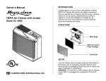
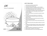
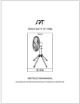
INSTRUCTION MANUAL
Micro-Computer Fan
Model: SF-1466
Thank you very much for your purchasing the SUNPENTOWN Stand Fan.
Please read the instructions carefully and keep for future reference.
IMPORTANT SAFETY INSTRUCIONS
Please read all instructions before using this product. Save these instructions for easy
reference. When using electrical appliances, basic precautions should always be
followed to reduce breakage, risk of fire, electric shock and injury to persons including
the following:
•
Do not use the fan outdoors.
•
Never use the fan unless it is fully assembled.
•
Do not use the fan under the following conditions: 1) High temperature of over 104F.
2) High humidity. 3) Steam filled room.
•
Do not push finger or any object through the grilles and do not touch the fan blade
during use. Be extra cautious when children and infants are around during use.
•
Take care that curtains or other objects are not sucked into the fan during operation.
•
Do not spray the fan with insecticide, which will damage the housing.
•
WARNING: The fan has a polarized plug (one blade is wider than the other). To
reduce risk of shock, this plug is intended to fit in a polarized outlet only one way. If
the plug does not fit fully in the outlet, reverse the plug. Do not attempt to defeat this
safety feature.
•
WARNING: To reduce the risk of fire or electric shock, do not use this fan with any
solid-state speed control device.
•
Unplug from wall outlet before servicing.
•
To avoid fire or shock hazard, the Stand Fan should ONLY be plugged into a
polarized 120 Volt AC outlet.
READ AND SAVE THESE INSTRUCTIONS
1
PARTS IDENTIFICATION
Handle
Fan Blade
Motor Head
Front Grille
Axle
Extension Tube
Height Lock
Base Stand
Foot of Base
Stand
Base
Plug
Power cord
Timer Knob
Control Panel
Remote Control
2
ASSEMBLY INSTRUCTION
A. Base Assembly
Lock Nut
1. Place Base on flat and sturdy ground.
2. Turn the Foot of Base Stand over and remove the
Lock Nut by turning counter-clock wise.
3. Insert Foot into base by aim the clip on the Foot to
the groove on the base and press down firmly.
Turn counterclock wise
Bottom view of
base stand
WARNING
During installation, take caution to not damage the insulation
of power cord.
4. Replace Lock Nut and turn clock-wise until tightened.
Turn clock
wise to lock
NOTE: To disassemble:
1. Remove Lock Nut by turning counter-clock wise.
2. Lift the rear of the Foot up and pull backwards.
3. Replace the Lock Nut back onto the Foot.
WARNING!
WARNING!
Do not stand immediately above the unit
when adjusting height, may cause
collision to body.
Do not plug in power source before the
unit is fully assembled. May cause
electric shock.
3
B. Blade Assembly
Axle
1. First, remove the following parts from the axle on the
motor head. Please remove before installing grilles:
Guard Lock Nut, Axle Sleeve and Lock Cap.
Guard
Lock Nut
Axle
Lock Cap
Axle
Sleeve
Guard
Lock Nut
2. Place the Rear Grille on the axle.
3. Place the Guard Lock Nut and tighten by turning clockwise.
Rear Grille
4. Place the Axle Sleeve on the Axle. (DO NOT USE)
5. Insert the Fan Blade on the Axle
6. Place the Lock Cap and tighten by turning COUNTER
clock-wise.
7. Install the Front Grille.
• Align the clip on the top of the front grill and clip it to
the rear grille.
• Press down firmly at the six points as indicated.
• Snap close the bottom clip
OPERATING INSTRUCTIONS
To Adjust the height of the stand: Press down on the Height
Lock and adjust height. Release when desired height is
reached.
The base includes a section to store the power cord, when unit
is not in use.
The base, by the control panel, includes a space to store the
remote control.
To place or replace batteries in the remote: remove back cover
of remote by sliding outward. Insert 2 AA batteries as indicated.
4
Guard Fan blade
Lock Nut
REMOTE AND CONTROL PANEL FUNCTIONS / INDICATIONS
REMOTE
CONTROL PANEL
POWER button
• Press once to turn unit ON
• Press again to turn unit OFF
FAN SPEED button
• Press to select fan speed in sequence: Low – Medium – High
TIMER button (timer-off setting only,)
• Press to set in sequence:
0 (or continuous) → 1 hr → 2 hr → 4 hr
OSCILLATION button
• Press once for Horizontal oscillation (left and right)
• Press again for Vertical oscillation (up and down)
• Press the third time for both Horizontal and Vertical oscillation, in
Horizontal and Vertical indicator lights will be lit.
MODE button
• Press once for Natural wind mode (please see below for details).
• Press again for Sleep mode (please see below for details).
• Press the third time to return to Normal mode.
5
shape. In this function, both
NATURAL WIND mode
Unit mimics the pattern of natural wind outdoors. The rhythm varies depending on the fan speed when
entered in Natural mode:
SLEEP mode
• If unit is set on High fan speed when entered in Sleep mode, unit will operate in High Rhythm for
0.5hrs, switch to Medium Rhythm for 0.5 hrs and then to Low Rhythm. Unit will continue operating in
Low Rhythm until Timer is up or manually turned off / change modes.
• If unit is set on Medium fan speed when entered in Sleep mode, unit will operate in Medium Rhythm
for 0.5 hrs, switch to Low Rhythm. Unit will continue operating in Low Rhythm until Timer is up or
manually turned off / change modes.
• If unit is set on Low fan speed when entered in Sleep mode, unit will operate in Low Rhythm
continuously until Timer is up or manually turned off / change modes.
Note: for pattern of High – Medium – Low Rhythm, please refer to patterns above.
6
MAINTENANCE
1.
2.
3.
4.
5.
6.
This product should be cleaned and checked on a regular basis.
Make sure the fan blade is clean at all times, to prevent color fading and damage.
For storage, clean and replace unit back in original packaging. Store in a cool, dry place.
To clean housing, wipe with clean damp cloth.
Never spray water directly onto the unit or immerse the unit/cord in water.
Do not use harsh chemicals such as acid, alcohol and the such on any part of the fan.
SPECIFICATION
Power Input: 120V / 60Hz
Power Consumption: High = 49W / Med = 40W / Low = 33W
R.P.M.: High = 1250 / Med = 1030 / Low = 850
Noise Level: 66 Db
Package Dimension: 16” x 10.7” x 4.25”
Your Guarantee
If this product is found to be faulty as a result of faulty materials or workmanship within one year from
date of purchase, it will be repaired free of charge.
This guarantee is subject to the following terms:
• Sunpentown must be notified of the fault.
• Proof of purchase must be presented to Sunpentown’s nominated representative.
• The warranty will be void if the product if modified, misused or repaired by an unauthorized
person.
• The warranty after repair will not be extended beyond the original one-year period.
• All replacement parts will be new or reconditioned.
• Parts, which are replaced, become the property of Sunpentown.
• The warranty applies for the use of the product in the USA only.
What is NOT COVERED:
•
•
•
•
•
Warranty does not include freight charges.
Incidental or consequential damage caused by possible defects with this product.
Damage to product caused by improper power supply voltage, accident, fire, floods or acts of
nature.
Failure of product resulting from unauthorized modifications to the product.
Improper installation or failure to perform the necessary maintenance.
This GUARANTEE is in addition to your Statutory Rights
Sunpentown Int’l Inc.
21415 Baker Parkway, City of Industry, CA 91789-5236
Tel: 909-468-5288 · Fax: 909-468-5279
[email protected]
www.sunpentown.com
7