1
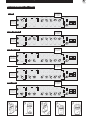
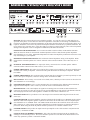
Laney
Alliance
USER MANUAL
MODEL : VC50
: VC100
: VH100R
Laney
1
INTRODUCTION
Congratulations on your decision to purchase a Laney amplifier.
Laney products are designed with ease of operation as a primary objective, however to ensure you derive the best from your
new amplifier, it is important you take time to read this user manual and to familiarise yourself with the control functions and
facilities available
BEFORE
SWITCHING ON
After unpacking your amplifier check that it is factory fitted with a three pin 'grounded' (or earthed) plug. Before plugging into
the power supply ensure you are connecting to a grounded earth outlet.
If you should wish to change the factory fitted plug yourself, ensure that the wiring convention applicable to the country where
the amplifier is to be used is strictly conformed to. As an example in the United Kingdom the cable colour code for
connections are as follows.
EARTH OR GROUND - GREEN/YELLOW
NEUTRAL - BLUE
LIVE - BROWN
This manual has been written for easy access of information. The front and rear panels of each unit are graphically illustrated,
with each control and feature numbered. For a description of the function of each control feature, simply check the number
with the explanations adjacent to each panel.
Your Laney valve amplifier has undergone a thorough two stage, pre-delivery inspection, involving actual play testing, as well
as valve burn in. Valves are the most important component in your Laney valve amp. However they are also the most fragile
component. The glass envelope and valve filaments can easily be damaged in transit without any apparent signs of damage to
the box, amp or valves. Valve damage is however quite simple to diagnose and even more simple to remedy. These procedures
are explained later in this manual..
When you first recieve your Laney valve amp, follow these simple procedures:
(i) Ensure that the amplifier is set at the correct voltage for the country it is to be used in.
(ii) Ensure that the speaker is connected to the appropriate socket.
(iii) Connect your instrument with a high quality shielded instrument cable. Use of cheap cables will compromise the sound
of your instrument and your amplifier.
If there is a problem with your Laney valve amplifier
DON'T
DO
PHONE YOUR DEALER!
Care of your Laney amplifier will prolong it's life.....and yours!. If you follow these guidelines your equipment will give you
years of playing pleasure
0V
22
2
MODEL VC50/VC100 & VH100R
RECOMMENDED SETTINGS
CLEAN
Reverb & Effect
levels should be
set to required
VOLUME
5
4
LO
Both HI and LO
inputs should be
experimented with INPUT
to obtain the sound
you are looking for.
HI
1
7
3
8
9
2
1
10
5
4
7
3
8
9
2
1
1
10
VOLUME
6
7
8
9
0
4
8
9
10
4
7
3
8
9
2
6
1
0
10
5
5
6
4
4
7
3
8
9
2
0
6
4
5
4
7
3
8
9
2
6
1
10
5
REVERB
TREBLE
6
1
10
5
5
0
6
4
7
3
8
9
2
0
5
6
4
VOLUME
4
5
1
0
3
8
9
2
1
10
5
4
7
8
9
1
0
4
6
10
5
6
4
3
7
3
7
3
7
3
7
3
7
8
9
2
8
9
2
8
9
2
8
9
2
8
9
2
8
9
1
0
1
10
0
VOLUME
1
0
10
1
10
0
1
0
10
MIDDLE
BASS
1
0
10
REVERB
TREBLE
8
9
0
7
3
8
9
2
1
10
4
1
6
8
9
0
10
4
2
0
7
6
3
10
5
5
4
7
3
8
9
2
5
6
1
10
5
MIDDLE
BASS
VOLUME
6
7
4
6
3
2
1
5
4
7
CHANNEL
5
6
3
7
8
9
2
1
10
0
STANDBY
POWER
STANDBY
POWER
STANDBY
POWER
STANDBY
POWER
STANDBY
POWER
10
PRESENCE
EFFECTS
0
6
4
4
7
3
8
9
2
0
6
4
5
4
7
3
8
9
2
6
1
0
10
5
REVERB
TREBLE
6
1
10
5
5
6
3
8
9
2
5
0
6
4
EFFECTS
4
6
1
10
5
4
4
7
7
3
8
9
2
RESONANCE
6
7
8
9
1
0
10
5
5
4
6
10
5
6
4
3
7
3
7
3
7
3
7
3
7
3
7
2
8
9
2
8
9
2
8
9
2
8
9
2
8
9
2
8
9
1
0
1
10
0
VOLUME
GAIN
DRIVE
1
0
10
1
10
0
0
10
MIDDLE
BASS
1
1
0
10
REVERB
TREBLE
ROCK RHYTHM
CHANNEL
5
6
3
7
8
9
2
1
10
0
10
PRESENCE
EFFECTS
Reverb & Effect
levels should be
set to required
VOLUME
5
4
2
1
0
3
8
9
2
1
7
3
2
8
9
2
0
1
10
VOLUME
6
7
8
9
0
4
8
9
10
4
7
3
8
9
2
6
1
0
10
5
5
6
4
4
7
3
8
9
2
0
6
4
5
4
7
3
8
9
2
6
1
0
10
5
REVERB
TREBLE
6
1
10
5
5
6
4
7
3
8
9
2
0
5
6
4
EFFECTS
4
6
1
10
4
5
7
3
8
9
2
RESONANCE
6
7
8
9
1
0
10
5
5
6
4
10
5
6
4
3
7
3
7
3
7
3
7
3
7
3
7
2
8
9
2
8
9
2
8
9
2
8
9
2
8
9
2
8
9
1
0
1
10
0
VOLUME
GAIN
DRIVE
4
1
6
MIDDLE
BASS
6
2
0
7
0
5
3
10
5
4
6
3
1
5
4
7
10
5
4
DRIVE
BRIGHT
6
3
HI
2
6
7
DRIVE
BRIGHT
6
2
0
LO
Both HI and LO
inputs should be
experimented with INPUT
to obtain the sound
you are looking for.
8
9
5
Reverb & Effect
levels should be
set to required
3
HI
3
3
CLEAN CRUNCH
LO
Both HI and LO
inputs should be
experimented with INPUT
to obtain the sound
you are looking for.
7
10
5
RESONANCE
EFFECTS
4
6
1
10
4
5
2
GAIN
DRIVE
4
1
6
MIDDLE
BASS
6
2
0
7
0
5
3
10
5
4
6
3
2
0
5
4
2
0
DRIVE
BRIGHT
6
3
1
0
10
1
0
10
0
10
MIDDLE
BASS
1
1
0
10
REVERB
TREBLE
BLUES LEAD
CHANNEL
5
6
3
7
8
9
2
1
10
0
10
PRESENCE
EFFECTS
Reverb & Effect
levels should be
set to required
VOLUME
5
4
LO
Both HI and LO
inputs should be
experimented with INPUT
to obtain the sound
you are looking for.
HI
2
1
0
3
8
9
2
1
7
8
9
0
8
9
0
5
8
9
10
4
3
8
9
2
5
6
1
6
4
7
8
9
1
0
5
0
2
5
3
8
9
2
0
4
7
8
9
1
0
5
5
8
9
2
0
5
8
9
2
2
0
5
3
8
9
2
1
0
ROCK LEAD
6
7
8
9
0
4
10
5
6
4
7
3
7
8
9
2
8
9
1
0
10
REVERB
TREBLE
5
1
6
2
10
4
7
10
3
RESONANCE
EFFECTS
6
1
4
8
9
1
5
0
7
MIDDLE
BASS
3
6
3
10
4
7
10
4
8
9
6
1
0
7
1
10
3
6
2
5
4
7
10
3
REVERB
TREBLE
6
1
6
2
10
4
7
10
3
VOLUME
GAIN
DRIVE
4
7
10
3
MIDDLE
BASS
6
1
0
7
0
5
2
6
2
10
4
3
10
3
1
VOLUME
6
7
4
6
3
2
1
5
4
7
10
5
4
DRIVE
BRIGHT
6
3
CHANNEL
5
6
3
7
8
9
2
1
10
0
10
PRESENCE
EFFECTS
Reverb & Effect
levels should be
set to required
VOLUME
4
5
3
2
LO
Both HI and LO
inputs should be
experimented with INPUT
to obtain the sound
you are looking for.
HI
1
0
4
DRIVE
BRIGHT
7
3
8
9
2
1
10
5
7
3
8
9
2
0
10
DRIVE
1
VOLUME
6
7
8
9
0
4
6
3
2
1
5
4
6
4
6
7
8
9
0
10
GAIN
4
1
0
4
7
3
8
9
2
5
6
1
0
10
5
MIDDLE
BASS
6
2
10
5
5
3
6
4
4
7
3
8
9
2
0
6
4
4
7
3
8
9
2
5
6
1
10
5
REVERB
TREBLE
6
1
10
5
5
0
6
4
4
7
3
8
9
2
0
6
4
7
3
8
9
2
5
6
7
8
9
1
0
10
5
RESONANCE
EFFECTS
4
6
1
10
5
5
4
6
10
5
6
4
3
7
3
7
3
7
3
7
3
7
3
7
2
8
9
2
8
9
2
8
9
2
8
9
2
8
9
2
8
9
1
0
10
VOLUME
1
0
10
BASS
1
0
10
MIDDLE
1
0
10
TREBLE
1
0
10
REVERB
1
0
10
EFFECTS
CHANNEL
5
6
3
7
8
9
2
1
0
10
PRESENCE
3
MODEL VC50/VC100/VH100R
1a
2
3
VOLUME
4
5
2
1
0
INPUT
4
HI
8
9
2
1
7
3
2
8
9
2
1
10
8
9
0
1
4
1
0
6
7
8
9
0
10
DRIVE
GAIN
20
19 18
4
4
7
3
8
9
2
6
1
0
10
5
5
6
4
4
7
3
8
9
2
0
6
4
3
8
9
2
6
1
10
5
5
4
7
0
6
4
4
7
3
8
9
2
0
6
4
EFFECTS
6
1
10
5
5
4
7
3
8
9
2
5
RESONANCE
7
8
9
0
6
4
10
5
6
7
3
7
3
7
3
7
3
7
3
7
2
8
9
2
8
9
2
8
9
2
8
9
2
8
9
2
8
9
0
10
VOLUME
1
0
10
BASS
1
0
10
MIDDLE
1
0
1
10
TREBLE
0
10
REVERB
1
0
5
4
3
1
14 15
6
1
10
5
12 13
11
REVERB
TREBLE
6
1
10
5
5
10
9
MIDDLE
BASS
6
2
10
5
5
3
8
7
VOLUME
6
7
4
6
3
0
1b
3
10
5
5
4
7
6
5
DRIVE
BRIGHT
6
3
LO
4
10
EFFECTS
17
CHANNEL
6
3
7
8
9
2
1
0
STANDBY
POWER
10
PRESENCE
16
EXPLANATION OF TERMS
N.B. It should be noted that the layout of the control panel is reversed and inverted on the VH100R when compared to the layout diagrams
1a
LO INPUT: This input is attenuated down approximately 6dB from the high input. It is useful in obtaining
output that is "tight" not "mushy" from high gain humbucker type pickups.
2
VOLUME: Adjusts the overall volume of the clean channel
3
BRIGHT SWITCH: Adds brightness and sparkle to the upper frequencies of the clean and clean drive
channel
4
5
6
7
8
9
10
DRIVE: This pot controls the amount of 'Valve" drive applied to the circuit.
VOLUME: Sets the overall volume level of the clean channel drive sound.
1 DRIVE SWITCH: Engages the clean channel drive sound (Also footswitchable)
BASS: Controls the low frequency EQ in the pre amplifier.
MIDDLE: Controls the mid frequency EQ in the pre amplifier.
TREBLE: Controls the high frequency EQ in the pre amplifier
REVERB: Controls the level of reverb assigned to each channel
11
EFFECTS: Controls the signal level upon its return from an external processor and blends it to the desired
level with the main signal.
12
CHANNEL SWITCH: Selects the required channel which is displayed by an illuminated indicator. The upper
channel produces the clean tone and mild overdrive that is reminiscent of a sixties American valve combo. The
lower channel produces the more substantial overdrive and distortion that is associated with British valve
stacks.
11 13
14
RESONANCE: Adjusts the 'damping' control of the amplifier speaker enclosure, thereby controlling the
'tightness' of the bass responce. This effect is very cabinet dependant so the switch should be adjusted to taste.
STANDBY: This switch enables/disengages the high voltage DC to the valves, switching the amplifier from a
'wait state' to an 'active state'. The AC voltage to the heaters is not effected by this switch so that an instant on
of the amplifier is achieved when switching to an active state, so long as the POWER SWITCH has remained in
the ON position. Always switch the amplifier to the 'STANDBY' before turning the main power switch off.
This will prolong valve life
4
MODEL VC50/VC100/VH100R
2
1a
3
VOLUME
4
5
2
1
0
INPUT
HI
8
9
2
1
3
2
8
9
2
1
1
10
4
8
9
0
1
0
6
4
7
8
9
0
10
DRIVE
GAIN
20
19 18
4
7
3
8
9
2
6
4
7
3
8
9
2
1
0
10
5
5
6
4
0
6
4
3
8
9
2
6
1
10
5
5
4
7
0
6
4
4
7
3
8
9
2
EFFECTS
6
4
1
0
10
5
5
6
4
7
3
8
9
2
5
RESONANCE
7
8
9
0
6
4
10
5
6
7
3
7
3
7
3
7
3
7
3
7
8
9
2
8
9
2
8
9
2
8
9
2
8
9
2
8
9
0
1
10
0
VOLUME
1
0
10
1
10
0
MIDDLE
BASS
1
0
10
1
0
10
REVERB
TREBLE
5
4
3
2
1
14 15
6
1
10
5
12 13
11
REVERB
TREBLE
6
1
10
5
5
10
9
MIDDLE
BASS
6
2
10
5
5
3
8
7
VOLUME
6
7
4
6
7
1b
18
19
3
3
0
16
17
7
10
5
4
5
4
6
5
DRIVE
BRIGHT
6
3
LO
4
CHANNEL
6
3
7
8
9
2
1
10
0
STANDBY
POWER
10
PRESENCE
EFFECTS
16
17
PRESENCE: Controls the high frequency material in the power amplifier.
VOLUME: Adjusts the overall volume of the overdrive channel
GAIN: Adjusts the input level of the overdrive channel.
DRIVE SWITCH: Allows activation of the overdrive section from the front panel.
20
DRIVE: Controls the amount of valve overdrive. The overdrive is applied to the circuit just prior to the gain
control. The drive is engaged only when the drive switch (19) is on. The drive may be operated by the switch or
remotely by the footswitch (FS4) connected on the rear panel.
1b
HI INPUT: This input provides maximum gain from the instrument to the pre amp. It is extremely useful for
guitars with single coiled or low gain humbucker type pickups. Use of high gain pickups in this input may drive
the pre amp to severely, causing a "mushy" output.
VC50/VC100 BACK PANEL
POWER FUSE
4 OHM
HT FUSE
8 OHM
EXTENSION
CABINET
21
IN
LINE
POWER
AMP
INTERNAL
CABINET
OUT
PRE
AMP
FOOTSWITCH
6L6
5881
RETURN
LEVEL
BIAS
RETURN
EFFECTS LOOP
INSERT
SIDE
BYPASS SEND
CHAIN
SEND
RETURN
OVERDRIVRE CHANNEL B
A+B
RETURN
EFFECTS LOOP
SEND
RETURN
CLEAN CHANNEL A
30 31 32 33 34 35 36 37 38 39
24 25 26 27 28 29
22 23
INSERT
EL34
VH100R BACK PANEL
EFFECTS LOOP
A+B
INSERT
EFFECTS LOOP
RETURN
LEVEL
SEND
RETURN
CLEAN CHANNEL A
RETURN
SEND
RETURN
OVERDRIVRE CHANNEL B
SEND
INSERT
SIDE
BYPASS RETURN
CHAIN
FOOTSWITCH
6L6
5881
EL34
BIAS
IN
PRE
AMP
LINE
OUT
SPEAKERS
1x16 ohm
2x16 ohm
1x8 ohm
2x8 ohm
1x4 ohm
HT FUSE
POWER FUSE
POWER
AMP
42 41 40
21
POWER CONNECTOR: This is where the mains cable attaches.
22
POWER FUSE: This fuse protects the AC power of the overall amplifier. Use ONLY the correct size and rating
of fuse as specified on the panel. If a fuse blows or fails and a replacement of the same size and rating is installed
and it in turn blows, the amplifier has suffered a malfunction internally and needs immediate service from a
qualified technician DO NOT TRY USING A FUSE OF HIGHER RATING.
5
MODEL VC50/VC100/VH100R
VC50/VC100 REAR PANEL
POWER FUSE
4 OHM
HT FUSE
8 OHM
EXTENSION
CABINET
21
IN
LINE
POWER
AMP
INTERNAL
CABINET
OUT
PRE
AMP
FOOTSWITCH
6L6
5881
RETURN
LEVEL
BIAS
RETURN
EFFECTS LOOP
INSERT
SIDE
BYPASS SEND
CHAIN
SEND
RETURN
OVERDRIVRE CHANNEL B
A+B
RETURN
EFFECTS LOOP
SEND
RETURN
CLEAN CHANNEL A
30 31 32 33 34 35 36 37 38 39
24 25 26 27 28 29
22 23
INSERT
EL34
VH100R BACK PANEL
EFFECTS LOOP
A+B
INSERT
EFFECTS LOOP
RETURN
LEVEL
SEND
RETURN
CLEAN CHANNEL A
RETURN
SEND
RETURN
OVERDRIVRE CHANNEL B
SEND
INSERT
SIDE
BYPASS RETURN
CHAIN
FOOTSWITCH
6L6
5881
EL34
BIAS
IN
PRE
AMP
LINE
OUT
SPEAKERS
1x16 ohm
2x16 ohm
1x8 ohm
2x8 ohm
1x4 ohm
HT FUSE
POWER FUSE
POWER
AMP
40 41 42
23
24
HT FUSE: This fuse protects the DC power within the amplifier. Use only the correct size and rating fuse as
specified on the panel. If a fuse blows or fails and a replacement of the same size and rating is installed and it in
turn blows, the amplifier has suffered a malfunction, at this point check the output valves and replace faulty one if
required. Should the valves not be the problem the amplifier should be checked out by a qualified technician. Do
not try using a fuse of greater value. Using fuses that are too large in current rating may cause serious irrepairable
damage to the amplifier. Fuses are designed in to PROTECT, DO NOT take chances.
1EXTENSION SPEAKER SOCKET: Use to connect an 8ohm extension cabinet, model number GS212PE.
When an extension cabinet is connected the resultant impedance will be 4 ohms and the speaker impedance
switch should be set to 4 ohms. Mismatched impedance will reduce tha amplifiers performance and in some cases
may cause damage to your amplifier.
25
IMPEDANCE SELECTOR SWITCH: This switches the internal impedance setting of the amplifier. When
using with the 'on board' speaker set to 8 ohms. When an 8 ohm extension cabinet is also connected, set to 4
ohms.
26
INTERNAL SPEAKER SOCKET: 1/4" output jack factory connected to the 'on-board' speaker. With no
extencion cabinet connected ensure that switch (5) is set to 8 ohms.
27
POWER AMP/LINE IN: This socket is provided to allow a signal to be fed directly to the power amplifier from
an effects unit or other pre amplifier. Connection at this point disconnects the internal pre- amplifier. Nominal
level 0dBu.
28
POWER AMP/LINEOUT: This socket provides an output from the pre-amplifier, post FX loop and may be used
to drive other power amplifiers, FX units or mixing desks. Nominal level 0dBu.
29
BIAS SWITCH: This is factory set to suit the valves fitted (5881). Should you wish to use EL34 valves the bias
switch should be re-set accordingly.
30
FOOTSWITCH SOCKET: This is a 5 pin 180 DIN socket for connection of the dedicated footswitch FS4 as
supplied with the amplifier. FS4 is a four way switch for remote on both channels and reverb.
31
RETURN LEVEL: This control adjusts the signal level returning from an external FX unit and allows the
correct mix to be achieved. This may also be used to provide additional pre amp gain for both channels when the
switch is deployed in the insert mode regardless of whether an effect unit is connected or not.
32
RETURN SOCKET:This is provided to recieve the output of an external FX unit being driven from the send
socket (14)
33
FX MODE SWITCH: For normal amplifier operation without FX this should be set to 'BYPASS' mode position.
When the whole of the amplifier signal is required to be directed to an external effect, such as a Graphic Eq the
switch should be set to ' INSERT' mode. The 'SIDE CHAIN' mode allows the connection of FX units such as
delays, flangers etc, where a direct signal path is maintained to avoid the normal loss of dynamics through FX
processors. When using this mode any FX unit should if possible be set to 'EFFECT ONLY' mode.
34
FX SEND SOCKET: This provides an output from the pre-amplifier to drive effects units in conjunction with
(12) & (13). Nominal level 0dBu.
35
FX LOOP SEND (OVERDRIVE CHANNEL): This socket provides an output from the pre-amplifier for
sending to an external FX processor. Processors fitted here operate in a 'side chain' mode and should be set for
effect only operation if possible. Nominal level 0dBu
6
MODEL VC50/VC100/VH100R
VC50/VC100 REAR PANEL
POWER FUSE
8 OHM
4 OHM
HT FUSE
EXTENSION
CABINET
21
LINE
IN
POWER
AMP
INTERNAL
CABINET
FOOTSWITCH
6L6
5881
OUT
RETURN
LEVEL
BIAS
PRE
AMP
RETURN
EFFECTS LOOP
INSERT
SIDE
BYPASS SEND
CHAIN
SEND
RETURN
OVERDRIVRE CHANNEL B
EFFECTS LOOP
A+B
RETURN
SEND
RETURN
CLEAN CHANNEL A
30 31 32 33 34 35 36 37 38 39
24 25 26 27 28 29
22 23
INSERT
EL34
VH100R BACK PANEL
EFFECTS LOOP
INSERT
EFFECTS LOOP
A+B
FOOTSWITCH
RETURN
LEVEL
SEND
RETURN
CLEAN CHANNEL A
SEND
RETURN
OVERDRIVRE CHANNEL B
RETURN
SEND
INSERT
SIDE
BYPASS RETURN
CHAIN
6L6
5881
EL34
BIAS
LINE
IN
PRE
AMP
SPEAKERS
1x16 ohm
OUT
2x16 ohm
1x8 ohm
2x8 ohm
1x4 ohm
HT FUSE
POWER FUSE
POWER
AMP
40 41 42
36
FX LOOP RETURN (Overdrive Channel): This socket is provided to accept the output of an externalFX
processor being driven from (15). The return level mix is controlled via the front panel effects level control.
37
FX LOOP RETURN A+B: This socket is provided for use when a single effects unit is to be used, on both
channels, at different mix levels, via the front panel effect level controls. In this set up the effects units may be
driven from either channel send sockets.
38
FX LOOP RETURN (Clean Channel): This socket is provided to accept the output of an external effects
processor being drive from (19). The return level mix is controlled via the front panel effects control.
39
FX LOOP SEND (Clean Channel): This socket provides an output from the pre-amplifier for sending to an
external FX processor. Processors connected here operate in the 'side chain' mode so should be set for effect
only operation if possible. Nominal level 0dBu.
40
41
42
SPEAKER OUTPUTS (VH100R): A series of five 1/4" output jacks allows the user to correctly interface the
output impedance of the amplifier to the selected speaker enclosures. In following the cabinet impedance
information printed around the appropriate jack or jacks, correct operation and impedance matching is ensured.
Mismatched impedance will reduce the amplifiers performance and in some cases can cause irreparable damage.
Ancillary Connection Examples
POWER FUSE
HT FUSE
4 OHM
EXTENSION
CABINET
8 OHM
IN
LINE
POWER
AMP
INTERNAL
CABINET
OUT
FOOTSWITCH
6L6
5881
RETURN
LEVEL
BIAS
PRE
AMP
INSERT
EL34
RETURN
EFFECTS LOOP
INSERT
SIDE
BYPASS SEND
CHAIN
SEND
RETURN
OVERDRIVRE CHANNEL B
EFFECTS LOOP
A+B
RETURN
SEND
RETURN
CLEAN CHANNEL A
Slave
power amplifier
FX.C
FX.B
EG. Multi-FX unit
in 'side chain' mode
Laney
EG. Chorus
FX.A
EG. Slap back delay
In via power
amp socket
Nominal Level 0dBu
or Graphic EQ in insert mode
POWER FUSE
HT FUSE
4 OHM
EXTENSION
CABINET
8 OHM
INTERNAL
CABINET
IN
LINE
POWER
AMP
OUT
FOOTSWITCH
6L6
5881
PRE
AMP
Graphic EQ
Overall Graphic EQ
INSERT
EL34
BIAS
RETURN
LEVEL
RETURN
INSERT
SIDE
BYPASS SEND
CHAIN
FX.A & B
PROCESSORS
Overall Side Chain FX Units
EFFECTS LOOP
SEND
RETURN
OVERDRIVRE CHANNEL B
A+B
RETURN
EFFECTS LOOP
SEND
RETURN
CLEAN CHANNEL A
FX. A&B
PROCESSORS ONLY
Single FX unit used on
both channels with front
panel level controls.
7
USEFUL HINTS AND TIPS
The following hints and tips are provided so that you can get the best performance out of your Laney valve amplifier. These are only
guidelines and should be adapted for your own preferences:1: Valve amplifiers take a short time to 'warm up' to optimum operating temperature. To get optimum performance out of your amp
allow the amplifier to 'warm up' for three mins. before you begin playing.
2: The position of an amplifier in a room has an effect upon the overall sound characteristics. If you wish to increase the bass
responce of your amplifier place the amplifier on the floor. If you wish to reduce the bass response of your amplifier place the
amplifier on a stand.
3: Do not place you amplifier hard up against a wall as this will reduce the air circulating around the back of the unit and may result in
overheating.
4: Connecting your guitar to either the 'HI' or 'LO' input has an effect on the sound, regardless of the guitar type/pickup
configuration. The 'HI' socket provides more gain. The 'LO' socket provides a lower gain. You should experiment with both inputs
to find the one which suits your guitar, style of playing and gives you the most tonally pleasing results.
5: When using the 'BRIGHT SWITCH' on the amplifier keep in mind that it has a greater audible effect the lower the amount of
distortion produced by the preamplifier. At some distortion levels the 'BRIGHT SWITCH' may appear to have no effect at all.
VALVE REPLACEMENT AND TROUBLE SHOOTING
The valves in your new valve amplifier will eventually need replacing due to wear, this is normal with valve amps. In most instances
you
should be able
to effect valve replacement yourself
incurring the costs
of a service engineer. Following are some of the
VALVE
REPLACEMENT
ANDwithout
TROUBLE
SHOOTINGPS
most likely symptoms of valve malfunction and a suggested method of correction.
Normally valve amps give optimum performance when fitted with matched sets of output valves as factory fitted to all Laney valve
amps. NB: Damage will not occur by not fitting matched sets although the amplifiers performance may be impaired.
SYMPTOM 1
Amp connections have been performed correctly but power light fails to illuminate
SOLUTION 1
Check time delay POWER FUSE and replace if necessary:100-120 Volts 5 Amp time delay
220-240 Volts 2 Amp time delay
SYMPTOM 2
Power light illuminates, no sound out put
SOLUTION 2
Check secondary HT fuse and if blown replace with 1 amp time delay
VALVE IDENTIFICATION
3
4
1
2
5
Pre Amplifier
input valves
6xECC83
6
7
8
9
10
Power Aamplifier
output valves
4x5881 matched quartet
VALVE FUNCTIONS
1 First gain stage-Clean channel
2 2nd gain stage-Clean channel
3 First gain stage Drive channel
4 2nd gain stage Drive channel
5 3rd gain stage Drive channel
6 Power driver stage
7 & 8 2x5881 Output valves for VC50
7,8,9&10 4x5881 Output valves for VC100/VH100R.
8
SYMPTOM 3
Secondary HT fuse (1Amp time delay) blows repeatedly. This is a strong indication of a damaged output valve. The valve
function chart shows the valve layout and the function each performs.
SOLUTION 3
Replace the secondary fuse and turn on the power WITH STANDBY ENGAGED. View the output valves. If one of the
valves fails to light up, replace that valve. If both of the output valves are lit dimily, look directly at the output valves abd
disengage standby. If one of the valves flashes brightly or glows red hot in comparison to the adjacent valves, replace that
particular valve. A simple way to verify that the valve is damaged is to switch the position of the suspect valve and follow the
above procedure. If the valve exhibits the same symptoms in a different valve socket position, you can be certain that the
valve is damaged.
If the output valve checks out OK, another cause of a blown secondary fuse is a damaged Driver pre amp valve No.6. Replace
the Driver pre amp valve No.6 first and follow the above procedures. If the symptom persists, consult a qualified engineer, do
not fit a higher rated fuse.
SYMPTOM 4
No pre amplifier boost on Drive channel
SOLUTION 4
Replace pre amplifier valves No. 1 & 2.
SYMPTOM 5
No clean channel, drive channel OK.
SOLUTION 5
Replace pre amp valve No. 3 & 4
SYMPTOM 6
Slow loss of power
SOLUTION 6
Check first for damaged output valves (glowing ,flashing or dead) by using the procedures described in symptom 3. Next check
driver pre amp valve No.6.
All of these trouble shooting procedures can be performed quickly, without the aid of any sophisticated test gear. We suggest that
you always maintain spare valves for emergency purposes. Keep your Laney free of dirt, dust and moisture to prevent
performance failure Never subject your valve amp to environmental conditions that would not be comfortable to you!
Should other customer service be necessary, contact your authorised Laney dealer or call Laney service direct.
TECHNICAL SPECIFICATION
VC50
Maximum Power Consumption 200Watts
Supply Voltage (Factory Pre-set) 115/230 Volts
Supply Frequency
50/60Hz
Output Power
50 Watts
Input Impedance Hi
1 Meg Ohm
Input impedance Lo
470k Ohm
FX loop level (nominal)
0dB
FX send/return impedance
1k/100k Ohm
Speaker impedance
2x16 Ohm(8)
Extension speaker
8 Ohm
Speaker size
2x12"300mm
Speaker rating
80 Watts
VH100R
Maximum Power Consumption
Supply Frequency
Input Impedance Hi
FX Loop/Line level (all nominal)
250 Watts
50/60 Hz
1 Meg
0dB
VC100
Maximum Power Consumption
Supply Voltage (Factory Pre-set)
Supply Frequency
Output Power
Input Impedance Hi
Input Impedance Lo
FX loop level (nominal)
FX send/return impedance
Speaker impedance
Extension speaker
Speaker size
Speaker rating
250Watts
115/230 Volts
50/60Hz
100 Watts
1 Meg Ohm
470 K Ohm
0dB
1k/100k Ohm
2x16 Ohm (8)
8 Ohm
2x12/300mm
80 Watts
Supply Voltage (Factory Preset) 115/230 V
Output power
100 Watts
Input Impedance Lo
470 k Ohm
FX Send/Return impedance
1k/100 k Ohm
NEWLYN ROAD, CRADLEY HEATH
WEST MIDLANDS
B64 6BE
GREAT BRITIAN
In the interest of continuing product developement BLT Industries reserve the right to amend specifications without prior notice.