1
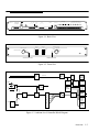
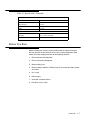
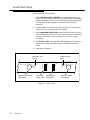
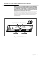
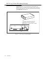
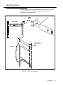
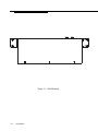
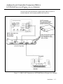
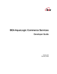
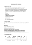
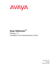
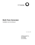
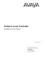
Ambient Level Controller
Installation and Use Manual
Issue 1, October 1999
© 1999 Bogen Communications, Inc.
All rights reserved. 54-2028-01 9910
Model: LUALC
PEC Code: 5335-621
COM Code: 408184273
Select Code: 701-000-131
© 1999 Bogen Communications, Inc.
All Rights Reserved. Printed in U.S.A.
Notice
Every effort was made to ensure that the information in
this guide was complete and accurate at the time of printing. However, information is subject to change.
FCC Statement (Part 15) - Radio Frequency
Interference
The Ambient Level Controller generates and uses radio frequency energy and, if not installed and used in strict accordance with the manufacturer's instructions, may cause interference to radio and television reception. Testing is being
conducted for compliance with the limits for a Class B
device in accordance with the specifications in Part 15 of
the FCC Rules. This testing is designed to provide reasonable protection against such interference. However, there is
no guarantee that interference will not occur in a particular
installation. If this equipment does cause interference to
radio or television reception, which can be determined by
turning the Ambient Level Controller unit off and on, the
user is encouraged to try to correct the interference by
one or more of the following measures:
- Reorient the radio or TV receiving antenna.
- Relocate the Ambient Level Controller unit with respect
to the radio or TV receiver or vice-versa.
- Plug the Ambient Level Controller unit into a different
outlet so that it and the radio or TV receiver are on different branch circuits.
If necessary, the user should consult the dealer or an experienced radio/television technician for additional suggestions. The user may find the following booklet, "How To
Identify and Resolve Radio-TV Interference Problems,"
helpful. This booklet was prepared by the Federal
Communications Commission (FCC) and is available from
the U.S. Government Printing Office, Washington, DC
20402. Stock order No. 004-000-00345-4.
Important Safety Information
Always follow these basic safety precautions when installing
and using the system:
1. Read and understand all instructions.
2. Follow all warnings and instructions marked on the product.
3. DO NOT block or cover the ventilation slots and openings. They prevent the product from overheating. DO NOT
place the product in a separate enclosure or cabinet, unless
proper ventilation is provided.
4. Never spill liquid on the product or drop objects into the
ventilation slots and openings. Doing so may result in serious damage to the components.
5. Repair or service must be performed by a factory
authorized repair facility.
6. The product is provided with a UL-CSA approved, 3-wire
ground type plug. This is a safety feature. DO NOT defeat
the safety purpose of the grounding type plug. DO NOT
staple or otherwise attach the AC power supply cord to
building surfaces.
7. DO NOT use the product near water or in a wet or
damp place (such as a wet basement).
8. DO NOT use extension cords. The product must be
installed within 6 feet of a grounded outlet receptacle.
9. DO NOT install telephone wiring during a lightning
storm.
10. DO NOT install telephone jacks in a wet location
unless the jack is specifically designed for wet locations.
11. Never touch uninsulated wires or terminals, unless the
line has been disconnected at the paging or controller
interface.
12. Use caution when installing or modifying paging or control lines.
Support Information
Paging systems integrated with small phone systems such as
Merlin Legend and Partner are supported by the National
Service Assistance Center (NSAC). The main number for
the NSAC is 800-628-2888. Paging systems integrated with
large switches such as the DEFINITY G3 are supported by
the Technical Service Center (TSC). The main number for
the TSC is 800-242-2121.
Contents
Page
1. Overview ....................................................................................................................................1-1
Features ............................................................................................................................1-2
Specifications ....................................................................................................................1-4
Before You Start ..............................................................................................................1-5
2. Operation .......................................................................................................2-1
Front Panel Setup ............................................................................................................2-2
Manual Use of the FM-15 Ambient Level Controller ............................................2-3
FM-14 Log Current Microphone Hookup ................................................................2-4
3. Installation .......................................................................................................3-1
Power Supply Hookup....................................................................................................3-2
Mounting Detail................................................................................................................3-3
Ambient Level Controller Connection With
LUUPAM Universal Paging Access Module................................................................3-5
Ambient Level Controller Connection With
LUPCM Paging System ................................................................................3-6
This page intentionally left blank
Overview
1
Contents
Features
1-2
Specifications
1-4
Before You Start
1-5
Overview
1-1
Features
■
Allows automatic, manual or remote control of sound system levels.
■
It has an SPL meter with over 50 dB range built in.
■
The microphone can be placed up to 5000 feet from unit.
■
Simplicity in set up and operation.
■
Single rack space - 1 RU.
■
Balanced 600 ohm inputs and outputs.
■
Line input activated by a contact closure.
■
Loop start TELCO input with priority over line input.
■
Clock inputs or remote control connections.
■
Relay outputs for emergency override or indicators.
■
Line output and a contact closure to supervise downstream equipment.
■
Internal microprocessor senses ambient noise via a microphone input, and
adjusts the paging level accordingly.
■
Rack or wall mount.
■
UL listed power supply, FCC Part 15 approved.
Figure 1-1 shows a back view of the Ambient Level Controller (ALC) and
Figure 1-2 shows a front view of the ALC. Figure 1-3 shows a block diagram
of the ALC.
1-2
Overview
Power Input
24 Volts AC
Line In
Telco In
Loop Start
C1 G
+ -
Clock Inputs or Remote Control
-24dB -24dB -18dB -12dB -6dB
Relay Outputs
Shield
Model FM-15
+ -
Mic Only
Mic Only
Line Out
Output
Level
NO
1
C
NC
NO
1
C
NC
NO
1
C
NC
NO
1
C
NC
C1 C
NO C
1
NO C
1
NO C
1
NO C
1
NO C
1
Figure 1-1. Back View
-18 dB
-24 dB
Manual Level Control
Noise Level
dB SPL
-12 dB
100dB
-6 dB
90dB
80dB
70dB
60dB
Paging Level
dB
105dB
Full Volume
95dB
-6 dB
85dB
-12 dB
75dB
-18 dB
65dB
-24 dB
Set Maximum Noise Level
95dB
100dB
90dB
85dB
105dB
Power
Automatic Level Control
Telephone Input Active
Figure 1-2. Front View
4 to
20 Mil
Rec.
0 to 5 Volt
LED
Driver
4 Bit
Converter
0 DBM
Audio
Detect
Gain Hold
C1
4 Bit
Converter
One of 8
AGC
0 dB
-6
-12
-18
Loop St
Clock
Inputs
FP Manual
or Automatic
Level
Control
Selection
Micro
68HC705
G
X 1 Buffer
4 Volume
Control
Over-rides
for High
Noise Level
LED
Display
X 1 Buffer
or Level
Set
600
600Ohm
Ohm
Bal line
Bal
line
Driver
Driver
FP
Selector
for Max.
Noise
-24
FP PA
Level
Display
Figure 1-3. Ambient Level Controller Block Diagram
Overview
1-3
Specifications
Table 1-1 lists the specifications for the ALC.
Table 1-1. Specifications
Parameter
Working Limits
Power Source
24 Volts AC UL listed power supply
Maximum Power Consumption
60 Watts
Frequency Response
250 Hz to 15KHz +/- 2dB
Signal To Noise [dB ref.]
Better than -60 dB
Maximum Output Level
0 dB,-12 dB with jumper
Output Relay Trigger Points
0 dB and -6 dB gain reduction
Output Relay Contact Rating
1 amp
No. of Relay Contacts
4
Input Level Controls [internal]
5
Control requirements
DRY contact closure
Input Types
Line
Telco, loop start
Output Types
Line [600 ohm]
Contact Closure On Output
Yes
Contact Closure Controlled Input
Yes
Front Panel Controls
Attenuation manual or automatic
Front Panel Indicators
Power
Attenuation, automatic
Telephone input active
REAR PANEL CONNECTORS
1-4
Overview
Relays
Compression screw
Microphone
RJ11-6 or compression screw
Line In
Compression screw
Line Out
Compression screw
Telephone
RJ11-6
Relay Outputs
Compression screw
Clock Inputs
Compression screw
Power
Compression screw
Microphone Type
Electret, omnidirectional
Maximum Mic Line Length
5000 feet
Table 1-1. Specifications (Continued)
PHYSICAL
Depth
8-3/4 inches
Width
With Rack Ears
17 inches
19 inches
Height
1-3/4 inches
Weight
8 pounds
ENVIRONMENTAL
Temperature
Operating
+32° to +104°F (0 to 40°C)
Humidity
0 to 85% Noncondensing
Before You Start
Before installing your system, read and understand the safety instructions.
Be sure you have all the necessary parts, tools, and test equipment, listed
below. Check the shipping container for the following contents:
1. FM-15 Ambient Level Controller.
2. FM-14 Log Current Microphone.
3. Rack mounting ears.
4. Rack mounting hardware (4 Phillips head 12-24 screws, 8 Phillips head 632 screws).
5. RJ-11 cord.
6. Power supply.
7. Installation and User Manual.
8. Male RCA to wires cable.
Overview
1-5
This page intentionally left blank
1-6
Overview
Operation
2
Contents
Front Panel Setup
2-2
Manual Use of the FM-15 Ambient Level Controller
2-3
FM-14 Log Current Microphone Hookup
2-4
Operation
2-1
Front Panel Setup
Set up the FM-15 ALC as follows:
1. Set the MANUAL LEVEL CONTROL to automatic (Blue Knob) (see
Figure 2-1). This allows the FM-15 ALC to calibrate itself.The automatic
position will allow the FM-15 ALC to constantly change the paging level
to compensate for the changes in noise level in the area being
monitored.
2. Check the SPL meter (the Green LED) (see Figure 2-1) for maximum
noise level. This is your high noise level reading.
3. Set the MAXIMUM NOISE LEVEL control (Red Knob) (see Figure 2-1)
to the average high noise level. If you feel the room noise may actually
be louder at some time, move the control up one click to the right
(clockwise).
4. The PAGING LEVEL meter (the Red LED paragraph) (see Figure 2-1)
indicates the paging level changes that are taking place with dual
LEDS.
5. Calibration is complete.
Telephone Input
Active
Automatic Level
Control
-18 dB
-24 dB
Manual Level Control
Noise Level
dB SPL
-12 dB
100dB
-6 dB
90dB
80dB
70dB
60dB
Manual Level Control
[Blue Knob]
SPL meter
[Green LED]
Paging Level
dB
105dB
Full Volume
95dB
-6 dB
85dB
-12 dB
75dB
-18 dB
65dB
-24 dB
Paging Level
[Red LED]
Figure 2-1. FM-15 ALC
2-2
Operation
Set Maximum Noise Level
95dB
100dB
90dB
85dB
105dB
Maximum Noise
[Red Knob]
Manual Use of the FM-15 Ambient Level Controller
The FM-15 ALC may be used without the FM-14 Log Current Microphone.
In this mode, the FM-15 ALC becomes a leveler or limiter for manual control
of the sound system. The SPL meter will not function but all other functions
will work in the normal manner. The Manual Level Control on the front panel
will set the level of the sound system (see Figure 2-1).
The Output Level Control (see Figure 2-2) is preset at the factory for a 0 dB
maximum output level. The Enable Contacts (see Figure 2-2) on the Line
Input terminal strip, when shorted with a DRY contact closure, will produce
an isolated DRY contact closure on the C1 and C terminals of the Line
Output terminal strip.
-12 dB
Output Level Control
J6
Minus 12dB Jumper
Telco In
Loop Start
Line In
C1 G
+ -
Line In Enable
Shield
TOP VIEW
Output
Level
Line Out
+ -
Mic Only
C1 C
Line Output Enable
Figure 2-2. FM-15 ALC Rear View
Operation
2-3
FM-14 Log Current Microphone Hookup
The wire for the FM-14 Log Current Microphone does not have to be
shielded. Use an RJ-11 connector at the microphone. When connecting to
the FM-15 ALC use an RJ-11 connector or wire directly to the terminal strip
marked MIC ONLY (see Figure 2-3).
OR
Output
Level
Line Out
+ -
Mic Only
NOTE: These terminals are redundant
MIC input connections, useful when a
Modular RJ-11 Plug and cable is not suitable.
Mic Only
NO
1
C
C1 C
Figure 2-3. FM-14 Log Current Microphone
2-4
Operation
Installation
3
Contents
Power Supply Hookup
3-2
Mounting Detail
3-3
Ambient Level Controller Connection With A
LUUPAM Universal Paging Access Module
3-5
Ambient Level Controller Connection With
LUPCM Paging System
3-6
Installation
3-1
Power Supply Hookup
Power Input
24 Volts AC
Telco In
Loop Start
Line In
C1 G
+ -
BLACK
WHITE
RED
GREEN
Model FM-15
Shield
Install the FM-15 ALC with the system to be controlled. Then install the
FM-14 Log Current Microphone in the area to be controlled. Connect the
power supply provided as marked on the PC board (BLACK-WHITE-REDGREEN, from left to right) (see Figure 3-1).
POWER SUPPLY
24VAC 1.6 60 HZ
DO NOT DEFEAT THE SAFETY GROUNDING PIN ON THE
POWER LUG.
Figure 3-1. Power Supply Hookup
3-2
Installation
Output
Level
Line Out
+ -
C1 C
Mounting Detail
The rack ears mount in any of four directions (see Figure 3-2). This makes
rack mounting or wall mounting possible. The power supply can be
mounted in any convenient place.
FRONT DETAIL
1.750
Typical
-18 dB
-24 dB
Manual Level Control
-12 dB
99dB
-6 dB
87dB
75dB
63dB
52dB
Noise Level
dB SPL
105dB
Paging Level
dB
Full Volume
93dB
-6 dB
81dB
-12 dB
63dB
-18 dB
53dB
-24 dB
Set Maximum Noise Level
93dB
99dB
87dB
81dB
105dB
Power
19"
PHILLIPS HEAD
#12-24 (TYPICAL)
REAR DETAIL
Figure 3-2. Rack Ears Mounting
Installation
3-3
Figure 3-3. Wall Mounting
3-4
Installation
Ambient Level Controller Connection With A
LUUPAM Universal Paging Access Module
The FM-15 ALC connects between the paging source (PBX, Key System or
standard telephone, and the paging amplifier) (see Figure 3-3).
NOTE: Loop start only.
Do not apply
Ring Voltage!
Figure 3-3. FM-15 ALC Connection to a LUUPAM Universal Paging Access Module
Installation
3-5
Note: The controller must be
switching line level only
Multiple FM-15 ALCs may be used with a single controller so each zone has its
own level correction (see Figure 3-4).
Figure 3-4. FM-15 ALC Used With A Paging Control System (LUPCMALL)
Installation
3-6