1
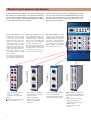
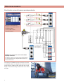
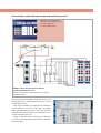
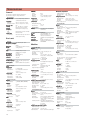
S U B S T A T I O N
A U T O M A T I O N
S O L U T I O N S
Faster testing
Easy to use
Flexible
TM1800
C i rc u i t B re a k e r A n a l y z e r S y s t e m
PROGRAMMA PRODUCTS
e
GE Energy Services
TM1800™ CIRCUIT BREAKER ANALYZER SYSTEM
! System platform for testing high voltage
circuit breakers
! Integrated static contact resistance measurement
! Expandable modular concept – high
flexibility (up to 48 + 48 timing channels)
! Automatic measurement of coil voltage
and current
! Stand-alone functionality – one toolbox
for all breaker testing
! Automatic measurement of a and b
auxilary contacts
! Designed for Off-line and On-line measurement
! Quick test functions
! Vibration measurement
! Analog or digital transducers for contact
travel measurements
! Temperature measurement
! Rugged and reliable for field use
! CABA backwards compatibility
! Calibration module for stable accuracy
! Multi-lingual Human-Machine Interface
! Predefined circuit breaker templates –
Automatic testing
! Enhanced reporting, assessments and
archiving of test results
! Enhanced contact timing
2
C IRCUIT
BREAKER ANALYZING
High voltage circuit breakers are extremely important
for the function of modern electric power supply systems. The breaker is the active link that ultimately has
the role of quickly opening the primary circuit when a
fault has occurred. Many times, the breaker has to perform its duty within a few milliseconds, after months,
perhaps years of idly standing by. Since condition based
maintenance has become the established strategy for
most owners and operators of electric power supply
systems, the need for reliable and accurate field test
instruments is obvious.
Market trends
Many new breaker technologies and designs have been
introduced over the past decades. At the same time,
the lifetime of an installed circuit breaker is often
longer than 40 years. This means that at most sites, the
vast range of existing circuit breakers with different
configurations present an enormous challenge to the
test engineers.
Another factor has been market driven reorganizations of electric power utilities. Frequently, the established service organizations within utilities have
given way to slimmed operations with outsourced maintenance and service. Again, this has meant that a lot of
practical know how and background history about specific breakers has been lost along the way.
The financial requirements on utilities have tightened
as well. Asset optimization has become a priority. The
possibility to continue using a costly circuit breaker
rather than unnecessarily replacing it with a new is very
interesting from this perspective – as long as it does not
put the safety and reliability of the electric power supply
at risk. This again puts the possibility to quickly and reliably diagnose the breaker’s condition into focus.
In line with Programma’s tradition, the new TM1800
Breaker Analyzer System is portable and rugged, making it suitable for use in any type of environment. The
concept is a flexible, modular system that can be easily
configured for any type of circuit breaker. Distribution
breakers with one contact per phase and one operating mechanism can easily be tested. Transmission
breakers often have a more complex design with several contacts per phase and separate operating mechanisms. Even here, TM1800 is fully capable of capturing any parameter. For example, when testing circuit
breakers with pre-insertion resistor (PIR) contacts,
TM1800 automatically measures timing of the main and
PIR contacts, as well as the resistance value of the pre
insertion resistor. Furthermore, with the TM1800 system, test methods such as static resistance measurement (SRM), dynamic resistance measurement (DRM)
and vibration testing are easily integrated in the circuit breaker testing.
TM1800 has a straightforward and user-friendly interface, CABA Local. The display is an 8-inch transreflecive screen that enhances the use in direct sunlight.
You can also use a separate PC with the optional CABA
Win software to prepare and evaluate the tests.
The user interface, CABA Local, has been designed
to facilitate setup and analysis. There are e.g. integrated
help functions that guides the user throughout the testing. Special efforts have also been made to reduce the
number of connecting leads required. Furthermore,
many functions have been automatized to reduce the
number of manual exercises and breaker operations
required to perform a test. As a result, the training
needed to use the TM1800 to its full extent is minimized and the time to carry out actual tests is brought
down to a minimum.
The reorganizations within the industry mentioned
above, (leading to outsourcing of service and maintenance), means that reporting, archiving and evaluation of test results become more critical. Modern service organizations need tools and facilities to provide
the breaker owner / operator with reports and recommendations in formats that are suitable.
The response
In response to all these challenges, GE Energy Services has designed the TM1800 breaker analyzer system.
The objective was to incorporate all relevant test functions in one compact unit that should be flexible
enough to test any circuit breaker that exist on the
market.
3
WHAT
NEEDS TO BE TESTED ON A CIRCUIT BREAKER
Timing measurements
Motion measurement
Simultaneity within a single phase is important in situations where a number of contacts are connected in
series. Here, the breaker becomes a voltage divider
when it opens a circuit. If the time differences are too
great, the voltage becomes too high across one contact, and the tolerance for most types of breakers is
less than 2 ms.
A high-voltage breaker is designed to interrupt a specific short-circuit current, and this requires operation
at a given speed in order to build up an adequate cooling stream of air, oil or gas (depending on the type of
breaker). This stream cools the electric arc sufficiently
to interrupt the current at the next zero-crossover. It is
important to interrupt the current in such a way that
the arc will not re-strike before the breaker contact
has entered the so-called damping zone.
The time tolerance for simultaneity between phases
is greater for a 3-phase power transmission system running at 50 Hz since there is always 6.67 ms between
zero-crossovers. Still, the time tolerance is usually specified as less than 2 ms, even for such systems. It should
also be noted that breakers that perform synchronized
breaking must meet more stringent requirements in
both of the aforesaid situations.
There are no generalized time limits for the time
relationships between main and auxiliary contacts, but
it is still important to understand and check their operation. The purpose of an auxiliary contact is to close
and open a circuit. Such a circuit might enable a closing coil when a breaker is about to perform a closing
operation and then open the circuit immediately after
the operation starts, thereby preventing coil burnout.
The A contact must close well in advance of the closing of the main contact. The B contact must open when
the operating mechanism has released its stored energy in order to close the breaker. The breaker manufacturer will be able to provide detailed information
about this cycle.
Speed is calculated between two points on the motion curve. The upper point is defined as a distance in
length, degrees or percentage of movement from a)
the breaker’s closed-position or b) the contact-closure
or contact-separation point. The time that elapses between these two points ranges from 10 to 20 ms, which
corresponds to 1-2 zero-crossovers.
The distance throughout which the breaker’s electric arc must be extinguished is usually called the arcing zone. From the motion curve, a velocity or acceleration curve can be calculated in order to reveal even
marginal changes that may have taken place in the
breaker mechanics.
Damping is an important parameter for the highenergy operating mechanisms used to open and close
a circuit breaker. If the damping device does not function satisfactorily, the powerful mechanical strains that
develop can shorten breaker service life and/or cause
serious damage. The damping of opening operations
is usually measured as a second speed, but it can also
be based on the time that elapses between two points
just above the breaker’s open position.
Contact closure
Arcing zone
Stroke
Position
Closed position
Speed calculation points
Damping zone
Open position
Time
4
Coil currents
Dynamic resistance measurements (DRM)
These can be measured on a routine basis to detect potential mechanical and/or electrical problems in actuating coils well in advance of their emergence as actual faults.
The coil’s maximum current (if current is permitted to
reach its highest value) is a direct function of the coil’s
resistance and actuating voltage. This test indicates
whether or not a winding has been short-circuited.
DRM procedures measure variations in contact resistance during breaker operation – not to be confused
with static resistance measurement, which measures
contact resistance when a breaker is closed.
When you apply a voltage across a coil, the current
curve first shows a straight transition whose rate of rise
depends on the coil’s electrical characteristic and the supply voltage (refer to picture1-2). When the coil armature
(which actuates the latch on the operating mechanism’s
energy package) starts to move the electrical relationship
changes and the coil current drops (3-5). When the armature hits its mechanical end position, the coil current
rises to the current proportional to the coil voltage (5-8).
The auxiliary contact then opens the circuit and the coil
current drops to zero with a current decay caused by the
inductance in the circuit (8-9).
The peak value of the first, lower current peak is related to the fully saturated coil current (max current),
and this relationship gives an indication of the spread to
the lowest tripping voltage. If the coil was to reach its
maximum current before the armature and latch start to
move, the breaker would not be tripped. It is important
to note, however, that the relationship between the two
current peaks varies, particularly with temperature. This
also applies to the lowest tripping voltage.
DRM has a number of applications. On certain types
of breakers DRM can be used to measure the shortening of arcing contacts. When breaker contact motion
is measured simultaneously with resistance, the results
can be used to determine the length of the arcing contact. In some cases, breaker manufacturers can supply
reference curves for the type of contact in question.
In another application, timing measurements can
be performed on a breaker with both sides grounded,
and it is difficult (because of practical considerations)
to disconnect one side from ground. If a sufficiently
high current is used (about 250 A or higher), there
will be a clearly evident step in the voltage change when
the breaker contact closes or opens in spite of the parallel ground connections. Similarly, DRM can be used
when a breaker has parallel main contacts.
Example of coil current on circuit breaker
1 Trip coil energized
6 Change in coil inductance
Example of DRM measurement
1 Motion measurement, phase C 6 Separation of main contact
2-3 Armature travel
3-4 Armature operates trip latch
4-5 Armature completes its travel
5 Armature hits stop
2
3
4
5
7
8
9
Proportional to DC coil resistance
Auxiliary contact opens
Current decay
Voltage drop, phase C
Timing, phase B
Timing, phase A
Start of motion
7
Separation of arcing contact
5
FLEXIBILITY
WITH MODULAR CONFIGURATION
TM1800 ascertain the condition of any circuit breaker type
and model from a wide range of circuit breaker manufacturers and with its modular design it permits user configurations for any application. It also enables upgrading for future
circuit breaker applications and designs.
The main part of the top panel is designed for the modules. You can configure your TM1800 with the type of module that suit your needs and of course add/replace modules whenever you like. In an“empty” slot there should always be a dummy module.
Controls the operation of the
circuit breaker. It gives a pulse
to the coil for close, open and
for the motor operation. The
module has three contact closures, one for each phase. For
1-phase operation use A for
close and B for open, C can be
used for motor operation or second trip coil. If two modules are
used you can have 3-phase operation with separate voltage
for all phases and close and
open operation.
The analog module is for measurement of any analog signal
measured with an industrial
standard transducer with voltage (10V) or current (4-20mA)
output. Typical quantities that
are measured are for example
motion, voltage, current, vibration (acoustic), pressure etc.
Measures the timing of the
main and parallel resistor contacts. Each pair of channels is
independent of the others and
has its own current limited DC
voltage source. Measurement
current is limited to 27 mA.
One channel can measure both
the main and the resistor contact and resistance of linear PIR.
For DRM measurements you
need two channels per break.
• The function of the sequence
is set in CABA Local
• Main contact timing
Digital
• Sequences C, O, C-O, O-C,
O-C-O
• Six channels per module
(grouped 3x2 in pairs with
common return)
Analog
• Three independent contact
functions per module.
Timing M/R
Control
The control module measures
coil current and voltage and timing of auxiliary a and b contacts.
• Three channels per module
Digital channels for measurement of motion, both linear and
rotary with incremental transducer.
• 10 V and 24 V output
• Measure with any industrial
standard analog transducer
• Parallel contact timing
• Six channels per module
• Parallel contact (PIR)
resistance
• Measurement ranges
transducer resolution up to
±32000 pulses.
• Power supply: 5 V and
12 V DC
6
On the top panel of the basic unit are the following inputs and outputs.
• Power supply
• Trig inputs and trig outputs
• External outputs for DRM trig and Warning signal (alerting nearby personnel that breaker
operation is about to take place).
• Earth (Ground) Connection
• Sync input and sync output
• Temperature transducer input
• Communication interfaces (USB, Ethernet etc)
Measures timing of any auxiliary contact, for example spring
motor auxiliary contacts.
• Thermal printer sensitive
line dot method
• Timing of contact or
voltage. Polarity insensitive.
• Printing speed 50mm/s (400
dot lines/s)
• Six channels per module
(each one separately)
grouping marked with
background colour
• Paper width 114mm (4")
Like any other measuring instrument TM1800 has to be calibrated to traceable standards on
a regular basis. With the calibration module the unit can be
calibrated in field.
PC-card module is a non-optional module, which is a part
of the basic unit. The two PCcard slots are for any type of
PCMCIA card i.e. storage, modem, network, wireless communication etc. The module also
contains the hard disk for the
system for easy extraction and
secures storage of recorded
data during transport.
This module is always in slot 10
in the module panel.
• The calibration module is
intended to be in slot 9 in
the module panel.
• You only need to send this
module for calibration and
you can use TM1800
without it.
PC-card
Printer
Timing Aux
A number of different printout
formats are available as well as
user adapted, both graphic and
numeric. You can have printouts
in English, German, French,
Spanish, Swedish. The printing
can be set to automatic printout
in CABA Local.
For on-site calibration of measuring inputs. The calibration
module is slightly smaller than
the other modules and has a
designated module place.
Calibration
For making printouts. Printouts
can also be made via parallel
(LPT) or USB output in top module or from PC with CABA Win.
• Two PC-card slots
• Type I/II/III PCMCIA cards
• 20 GB storage capacity on
built-in hard drive
• Optional: Flash disk
• Safety plug type of connections
7
A PPLICATION
EXAMPLES
Circuit breaker system with common operating mechanism
Minimum configuration of
modules for this application is:
1 Control module
1 Timing M/R module
1 Analog module
Y1 = Close coil
Y2 = Trip coil 1
Y3 = Trip coil 2
TM1800 Set-up for one main contact and common
operating mechanism
The drawing shows an analog measurement but it
can also be done with a digital module and incremental transducers.
The settings in TM1800 are easy to handle in the internal software CABA Local. Easy access via function keys
and the built in keyboard with track ball and a large,
bright screen wich is sharp as well indoor as in direct
sunlight.
8
Circuit breaker system with separate operating mechanism per pole
Minimum configuration of
modules for this application is:
2 Control modules
1 Timing M/R module
TM1800 set-up for two main contacts and one
operating mechanism per pole.
Motion measurement can be added with an analog
or digital module.
Above set-up shows complete wiring for pole A. The
timing hook-up for remaining pole B and C is done
accordingly to pole A.
Two control modules (six outputs) are needed to
control each coil (Y1/Y2) for every pole. The above
set-up shows the wiring of pole A. This also automatically tests timing on the auxiliary contacts that are connected in series to the coils.
When at site, doing the hook-up you can get help
on how to connect by pressing the i-button, see example to the right.
9
S PECIFICATIONS
General
Specifications are valid after 30 minutes warm up time.
Specifications are subject to change without notice.
Environment
Application field
Temperatur
emperaturee
Operating
Storage & transport
Enclosur
Enclosuree class
Humidity
Transpor
ransportt
Compliance
EMC
Safety
Cer
tifications
Certifications
CB-Certificate
For use in highvoltage substations
and industrial environments.
- 20°C to +50°C (-4°F to +122°F)
- 55°C to +85°C (-67°F to +185°F)
IP41
5% - 95% RH, non-condensing.
Operating and non-operating
ISTA 2A (unit in transport case)
EN 61326:1997+ A1:1998 + A2:2001
EN 61010-1:2001
IEC 61010-1:2001 (incl. all national
deviations) CE marking
Basic unit
General
Mains input
100 – 240 V AC, 50 – 60 Hz
Max power consumption
200 VA
Dimensions
513x175x438 mm (20.2"x17.2"x6.9")
Weight
15.5 kg (34.2 lbs)
Display
Type
Diagonal size
No. of pixels
Display mode
Luminance
Keyboard
Available languages
Pointing device
External input
Trig in
Voltage mode
Input range
Threshold level
Time inaccuracy
Contact mode
Output voltage
Output current
Threshold level
Transreflecting to increase
visibility in direct sunlight
21 cm (8")
800 x 600 (W x H)
256k colour
350 cd/m2
English, Swedish, Spanish, French,
German
Built-in trackball and mouse buttons
0 – 250 V AC/DC
User configurable in software in
steps of 1 V
±0.01% of reading ±0.1 ms
25 – 30 V DC
20 mA ±5 mA
1.5 kΩ ±0.5 kΩ
External outputs
General
No. of channels
3, (TRIG OUT, DRM, WARNING)
TRIG OUT
Switch
Electronic
Resolution
1 ms
Duration
User configurable in software
Inaccuracy
±0.01% of reading ±0.1 ms
Voltage mode
Output Voltage
12 V DC ±5%
Output Current
max 0.5 A
Contact mode
Making/Breaking range
max. 0.5 A
Resistive load
at 12 V
DRM
Switch
Relay
Resolution
10 ms
Inaccuracy
±0.01% of reading ±10 ms
Voltage mode
Output voltage
12 V DC ±5%
Output current
max 0.5 A
Contact mode
Making/Breaking range
max. 0.5 A
Resistive load
at 12 V
10
WARNING
Switch
Relay
Resolution
10 ms
Duration
User configurable in software
Inaccuracy
±0.01% of reading ±10 ms
Voltage mode
Output Voltage
12 V DC ±5%
Output Current
max 1 A
Contact mode
Making/Breaking range
max. 1 A
Resistive load
at 12 V
Temperature
Interface
for HighPrecision 1-wire® Digital
Thermometer
Communication interfaces
PC-cardd
Type I/II/III PCMCIA cards
PC-car
USB
Universal Serial Bus ver. 1.1
Ether
net
Ethernet
100 base-Tx Fast Ethernet
Printer por
portt
LTP, Multi-mode parallel (ECP/EPP/
SPP)
Serial por
portt
RS232, 9-pin D-Sub female
Exter
nal scr
een
External
screen
SVGA, up to 800 x 600 at 64k color,
2 MB SDRAM
Modules
Control Module
General
No. of channels
Time base inaccuracy
Resolution
Bandwidth
Measuring time
3
±0.01% of reading ±0.1 ms
0.1 ms
5 kHz
19 sec at 10 kS/s, 39 sec at
5 kS/s, 200 sec at 10 kS/s (Data
compression)
0 – 250 V AC/DC
1.0 kg (2.2 lbs)
Input voltage range
Weight
Non-bouncing switch
Function
Normally Open/Normally closed,
dual direction
Continuous current 16 A
Max current
60 A during 100 ms with
intermittence of 5%
Delay from trig in (if applicable)
<2.5 ms
Cur
Currrent measuring
Measuring range
±90 A
Resolution
3 mA (At data compression x 2)
Inaccuracy:
±1% of reading ±0.1% of range
Voltage measuring
Measuring range
±250 V
Resolution
20 mV
Inaccuracy
±1% of reading ±0.1% of range
Auxiliary contact status/r
esistance
status/resistance
Open circuit voltage 30 V ±10%
Short circuit current < 25 mA
Status threshold
Open > 10 kΩ > close
Resistance range
0 – 10 kΩ
Resolution
4 digits
Inaccuracy
±2% of reading ±0.2% of range
Timing M/R Module
General
No. of channels
6, in pairs of 2
Time base inaccuracy ±0.01% of reading ±0.05 ms
Resolution
0.05 ms
Bandwidth
5 kHz at ≤10 kS/s, 10 kHz at 20 kS/s
Measuring time
8 sec at 20 kS/s, 16 sec at
10 kS/s, 1000 sec at 20 kS/s (Data
compression)
Induction protection Capacitively coupled interference
current from surroundings max 20 mA
per channel.
Weight
0.8 kg (1.8 lbs)
Timing of main and rresistive
esistive contacts
Measuring voltage 55 V ±10%
Measuring current
≤27 mA ±10%
Status threshold
Main < 10 Ω <PIR < 10 kΩ < Open
PIR rresistance
esistance measur
ement
measurement
Supported PIR types Linear PIR
Measuring range
0 Ω – 10 kΩ
Inaccuracy
±10% of reading ±0.1% of range
Voltage measur
ement
measurement
Measuring range
±100 V, ±10 V, ±0.5 V,
Resolution
20 mV*, 0.4 mV*, 20 µV*
Inaccuracy
±1% of reading ±0.1% of range
* At data compression x 2
Analog Module
General
No. of channels
Time base inaccuracy
Sampling rate
Bandwidth
Measuring time
Transducer resistance
Weight
Output
Voltage output
Current output
Cur
Currrent measuring
Current meas. range
Resolution
Inaccuracy
Voltage measuring
Input voltage range
Measuring ranges
Resolution
Inaccuracy:
Digital module
General
No. of channels
Supported types
Time base inaccuracy
Measuring time
Weight
Output
Voltage
Current output
Digital input
Sampling rate
Range
Resolution
Inaccuracy
3
±0.01% of reading ±0.025 ms
1 – 40 kS/s
15 kHz
10 sec at 40 kS/s, 20 sec at 20 kS/s
500 Ω – 10 kΩ at 10 V output
0.8 kg (1.8 lbs)
10 V ±5%, 24 V ±5%
0 – 22 mA
0 – 22 mA
0.35 µA (At data compression x 2)
±1% of reading ±0.1% of range
0 – 250 V AC/DC
±10 V, ±250 V
0.3 mV, 20 mV
±1% of reading ±0.01% of range
6
Incremental transducers, RS422
±0.01% of reading ±0.05 ms
16 sec at 20 kS/s
0.7 kg (1.5 lbs)
5 V DC ±5% or 12 V DC ±5%
< 200 mA
1 – 20 kS/s
±32000 pulses
1 pulse
±1 pulse
Timing Aux Module
General
No. of channels
6
Time base inaccuracy ±0.01% of reading ±0.05 ms
Resolution
0.05 ms
Measuring current
< 25 mA
Measuring time
16 sec at 20 kS/s, 32 sec at 10 kS/s
Weight
0.8 kg (1.8 lbs)
Contact Mode
Measuring voltage 27 V ±10%
Status threshold
Closed < 100 Ω, Open > 1 kΩ
Inaccuracy
±5% of threshold
Voltage Mode
Input voltage range 0 – 250 V AC/DC
Status threshold
10 V
Inaccuracy
±0.5 V
Printer module
General
Printer type
Paper type
Printing speed
Horizontal resolution
Vertical resolution
Enclosure class
Weight
Thermal printer
Thermal 114 mm
50 mm/s (400 dotlines/s)
8 dots/mm
8 dots/mm
IP21
0.8 kg (1.8 lbs)
Calibration module
General
Reference Stability ±250 ppm per year
Weight
0.6 kg (1.3 lbs)
O RDERING
Dolphin clips
Ground cable
USB memory 256 Mb
Timing M/R cable
TM1800 Basic Unit ...................................................
Complete with:Transport case, User’s manual,
Mains and Ground cable, USB memory pen
Control module
...................................................
Complete with: 3 cable sets, 5 m ..... GA-00870
Timing M/R module ...................................................
Complete with: 3 cable sets, 5 m ..... GA-00850
3 dolphin clips, black .......................... 40-08320
6 dolphin clips, red .............................. 40-08322
Analog module
...................................................
Complete with: 3 cable sets, 10 m ... GA-01005
Digital module Cables delivered with transducers ..
Timing Aux module ...................................................
Complete with: 3 cable sets, 5 m ..... GA-00870
Calibration module ...................................................
Complete with: Calibration cable .. GA-001006
Printer module Complete with: Paper role ..............
Dummy module
...................................................
O PTIONAL
Analog module cable
Timing Aux cable
Transducers and mounting kit
Digital transducer cable
Cable reels
INFORMATION
Art. No:
CG-19090
CG-19030
CG-19080
CG-19000
CG-19040
CG-19060
CG-19020
CG-19050
CG-19010
ACCESSORIES
CABA Win R02A
.................................................... SA-02000
Temperature Sensor with sensor cable, 5 m ............ XB-31010
Motion Transducers – Rotary - Digital
1-phase Ready-to-Use Digital Rotary Transducer .... XB-39110
3-phase Ready-to-Use Digital Rotary Transducer .... XB-39120
Complete with: Mounting and calibration kit
Baumer BDH Digital transducer ................................. XB-39130
Complete with: Transd.cable & Flex coupling
Motion Transducers – Rotary - Analog
1-phase Ready-to-Use Analog Rotary Transducer ... XB-31091
3-phase Ready-to-Use Analog Rotary Transducer ... XB-31093
Complete with: Mounting and calibration kit
IP 6501 rotary transducer 357° ................................... XB-31010
Complete with: Tranducer cable
Motion Transducers – Linear - Analog
TLH 500 linear transducer 500 mm (20") travel. ....... XB-30020
LWG 225 linear transducer, 225 mm (9") travel. ...... XB-30117
TS 150 linear transducer 150 mm (6") travel. .......... XB-30030
Mounting kits
Kit for TLH, LWG, TS and IP transducers. ................. XB-39010
Kit for linear transducers, TLH/LWH ......................... XB-39065
Kit for vibration transducers ...................................... XB-39070
Kit for calibration of rotary transducer, IP6501 ........ XB-39095
Breaker-Specific Transducer Mounting Kits
For HPL circuit breaker (ABB) ..................................... XB-39080
For LTB circuit breaker (ABB) ..................................... XB-39090
For BLG operating mechanism (ABB) ....................... XB-39085
Extension cables
Analog cable TM1800, XLR female to male, 10 m .. GA-01005
For Analog and Timing M/R cables and
temperature sensor
Cable reel, 20 m (65.5 ft) ................................ black GA-00840
........................................... red GA-00842
......................................... blue GA-00846
...................................... green GA-00845
..................................... yellow GA-00844
Dynamic resistance measurement
DRM1000 Injection Control ........................................ BL-90041
Complete with: Connection box, Cables (red
and blue for vehicle battery) and Sensing cables
Vibration testing
Signal Conditioning Amplifier SCA606 ..................... BL-13096
Accelerometer DYTRAN 3200B5 ................................ XB-32010
Vibration Analysis Software
Separate CABA option for DTW -analysis. ........... BL-8270X
Please contact GE Energy Services for more
information on optional accessories.
11
S U B S T A T I O N
A U T O M A T I O N
S O L U T I O N S
TM1800
C i rc u i t B re a k e r A n a l y z e r S y s t e m
PROGRAMMA PRODUCTS
e
GE Energy Services
NOTICE OF COPYRIGHT & PROPRIET
ARY RIGHTS
PROPRIETARY
© 2003, Programma Electric AB. All rights reserved.
The contents of this document are the property of Programma Electric AB. No part of this
work may be reproduced or transmitted in any form or by any means, except as permitted in
written license agreement with Programma Electric AB.
Programma Electric AB has made every reasonable attempt to ensure the completeness and
accuracy of this document. However, the information contained in this document is subject to
change without notice, and does not represent a commitment on the part of Programma
Electric AB.
TRADEMARK NOTICES
Programma® is a registered trademark of Programma Electric AB. The GE logo is registered
trademark of General Electric Company. All other brand and product names mentioned in this
document are trademarks or registered trademarks of their respective companies.
Programma Electric AB is certified according to ISO 9001.
Programma Electric AB
Eldarvägen 4
SE-187 75 TÄBY
Sweden
Phone +46 8 510 195 00
Fax +46 8 510 195 95
E-mail [email protected]
Internet www.gepower.com
Printed matter No. ZI-CG01E R01A 2003
GEA-13519