1
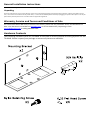
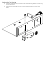
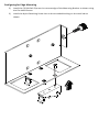
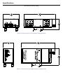
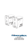
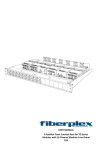
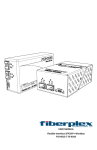
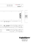
USER MANUAL TD‐Series DIN Rail Mount TD‐DINR General Installation Instructions Please consider these general instructions in addition to any product‐specific instructions in the “Installation” chapter of this manual. Unpacking Check the equipment for any transport damage. If the unit is mechanically damaged, if liquids have been spilled or if objects have fallen into the unit, it must not be connected to the AC power outlet, or it must be immediately disconnected by unplugging the power cable. Repair must only be performed by trained personnel in accordance with the applicable regulations. Warranty, Service and Terms and Conditions of Sale For information about Warranty or Service information, please see our published ‘Terms and Conditions of Sale’. This document is available on fiberplex.com or can be obtained by requesting it from [email protected] or calling 301.604.0100. Hardware Contents The following hardware parts are included to facilitate all of the possible mounting options for the TD‐DINR. Please inspect your package to ensure all pieces are available: Introduction The FiberPlex TD‐DINR is a specialized Mounting Bracket intended to mount a single FiberPlex TD‐ Series unit onto DIN rail conforming to standard EN 50022 (top hat sections only). Either 35 x 7.5mm or 35 x 15mm section DIN rail will be compatible with this device. Possible mounting configurations are: Flat mounting, the lower profile but wider rail signature Or Edge mounting, the higher profile but narrower rail signature Key Features Tool‐less DIN rail attach/detach Tool‐less TD unit mount/dismount Mounting configuration requires no alteration of the chassis Provision is made for cooling airflow Getting Started Initial Inspection Immediately upon receipt, inspect the shipping container for damage. The container should be retained until the shipment has been checked for completeness and the equipment has been checked mechanically and electrically. If the shipment is incomplete, if there is mechanical damage, or if the unit fails to operate notify FiberPlex and make the shipping materials available for the carrier's inspection. Configuring for Flat Mounting 1) Install the (2) DIN Rail Clips on the wide surface of the Mounting Bracket as shown using the Flat Head Screws 1) Install the Nylon Retaining Screw into to the threaded bushing on the small tab as shown Configuring for Edge Mounting 2) Install the (2) DIN Rail Clips on the narrow edge of the Mounting Bracket as shown using the Flat Head Screws 3) Install the Nylon Retaining Screw into to the threaded bushing on the small tab as shown Mounting the TD Module Mount the TD unit in the same manner regardless of the initial configuration of the mount itself or the height of top hat DIN rail utilized (35 x 7.5 or 35 x 15mm). The edge mounting solution happens to be shown below. All fasteners necessary for configuration and mounting are included. 1) Line up key hole on the bottom of the TD Module with the studs on the Mounting Bracket and push flat against the plate. 2) Slide the TD module forward until it stops. 3) Tighten the Retaining Screw until snug. 4) Snap the Rail Clips on to the DIN Rail. Specifications All units are Inches [mm] Figure 2 Dimensions for Flat Mount Configuration Figure 1 Dimensions for Edge Mount Configuration UMTDDIN 150107 18040-412 Guilford Rd. • Annapolis Junction, MD 20701 fiberplex.com • [email protected] • 301.604.0100