1
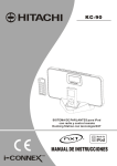
IQD10ZS High Resolution 600 TVL Mini Speed Dome CCTV Camera 10x Optical Zoom User Manual IQD10ZS -‐ User Manual Contents 1. PRODUCT INTRODUCTION 1.1 FEATURES …………………………………………………………………………………….……………….… 3 1.2 FUNCTIONS ………………….……………………………………………………………………………….... 4 1.3 PACKAGED CONTENTS …………………………………………………………………………..……..…. 4 2. INSTALLATION 2.1 INSTALLATION WARNING …………………………………………..…………………………..…..…… 5 2.2 BRACKET INSTALLATION ….……………………………………………………………….…………….. 7 2.3 WIRING …………………………………………………………………………………………….…………….. 8 3. OPERATING BASICS 4. MENU SETTINGS 4.1 MAIN MENU ……………………………………………………………………………………………..……. 10 4.2 SYSTEM INFORMATION …………………………………………………………………….……………. 11 4.3 ADDRESS SETTING ……………………………….…………………………………………………………. 12 4.4 MOTION (PAN/TILT SETTINGS) …………..………………………………………………….………... 11 4.5 PATTERNS …………………………………………………………………………………………..…………. 13 4.6 CAMERA …………………………..…………………………………………………………………………… 14 4.7 CRUISE SETTING (Tour) ….……………………...……………….………………………………………. 14 4.8 DISPLAY SETUP ………………………………………………………..………………….…………………… 15 5. TROUBLESHOOTING 5.1 TROUBLE SHOOTING TABLE …………………………………………….……………………………… 15 2 IQD10ZS -‐ User Manual 1. PRODUCT INTRODUCTION 1.1 FEATURES Advanced Pan Tilt Zoom functionality: § Automatic recognition for RS 485 control protocol § Recognizes 2400, 4800, 9600 Baud Rate (Compatible with PELCO D/P protocols). § Complete 360 degree° rotation and 90° vertical rotation allows surveillance without any blind spots § High speed Pan Tilt rotation § Based on vector drive technology that ensures the Pan & Tilt motion takes the most efficient and shortest path when viewing Presets § Features an advanced micro-‐stepping motor that allows the Pan/Tilt rotation reach speeds of 0.05 degree/sec. This allows the video image to be more accurate and stable under high magnification times. Presets and Tours § Maximum of 256 Presets (every Preset includes a lens magnification and viewing angle position) § Records up to 1 predefined tour (which consists of a maximum of 20 Presets) § Set up the left and right border of specified zones § Execute Pan Tilt Zoom functions at specified speeds § A Preset can include a continuous 360° scan On Screen Display (OSD) Menu § Built-‐in OSD screen menu that allows you to easily access and modify the speed dome’s operating parameters/settings § Operating information such as horizontal/vertical viewing angle, magnification of the lens and Preset in use, can be displayed on screen for the operator. 3 IQD10ZS -‐ User Manual 1.2 FUNCTIONS § Setup of address code: The IQD10ZS allows the user to manually set the camera’s protocols such as its ID address, baud rate and RS485 protocol. § Automatic turnover: When the camera reaches its maximum tilt position, by continuing the movement on a PTZ controller, the lens will automatically flip 90° and rotate 180° horizontally. Therefore the user will not have to scroll all the way back to the opposite viewing angle, allowing them to a achieve 180 ° continuous surveillance. § Reserve and Call Preset: Users can store up to 256 Presets which can be set via the speed dome itself or via a compatible controller § Lens/Iris Control: The camera’s lens can be fully controlled via a PTZ controller such as the zoom and focus. Additionally if you want to reset lens (i.e. auto-‐focus) the user can simply shake the PTZ controller’s joystick (left to right) or set up a relevant Preset. § Night vision: The Speed Dome will automatically switch to its nightvision mode once the illumination levels drop to a user specified level (Optional infrared lighting is required for the camera to view in nightvision mode) § Patterns: The camera can store up to 4 patterns which can then be launched by the PTZ controller as predefined presets (i.e. numbers 84, 85, 86, and 87) § Tours: The camera can store 1 Tour, which allows the camera to move to a user-‐defined pattern, which itself is a sequence of user-‐defined Preset points. The tour can then be easily launched by the PTZ controller. 1.3 PACKAGE CONTENTS The packaged box for the IQD10ZS comes with the following items: § § § § § § IQD10ZS Speed Dome Camera Wall Bracket Power Supply Screws Allen key User Manual Should any of these items be missing please contact your local distributor. 4 IQD10ZS -‐ User Manual 2. INSTALLATION INSTRUCTIONS 2.1 Warning WARNING: This symbol is intended to alert the user to the presence of non-‐insulated “dangerous voltage”. CAUTION: This symbol is intended to alert the user to presence of important operating and maintenance (Servicing) instructions in the literature accompanying the appliance. Disposal of Old Electrical & Electronic Equipment (Applicable in the European Union and other European countries with separate collection systems-‐ WEEE). This symbol on the product or on its packaging indicates that this product should not be treated as household waste. Instead, you should make arrangements for the recycling of this unit. By ensuring this product is disposed of correctly, you will help to prevent harm to the environment, and avoid possible health issues, which may be caused by inappropriate waste handling of this product. The recycling of materials helps to conserve our natural resources. For more detailed information about recycling of this product, please contact your local council office, your household waste disposal service or the shop where you purchased the product. In addition you can find further information online at www.environment-‐agency.co.uk 5 IQD10ZS -‐ User Manual Prior to installation and use of this product, please observe the following points: § Installation and servicing should be carried out by qualified service personnel. § It is important that the dome camera is not left in a position where the camera is pointing directly at the sun or other extremely bright light source. This may result in CCD damage and poor image quality. § The installation position must be as far away from high voltage sources as possible. § The dome cover is high quality optical product -‐ Try to avoid touching it as any scratches or marks left on the surface could affect image quality (we recommend the use of cotton gloves when handling). Please refer to the installation manual for further guidance § In order to get the optimum image at all times, the dome cover should be cleaned periodically. Be careful when cleaning; only hold the cover edge, avoiding direct contact with the dome cover. Acid from fingerprints will damage the coated surface of the dome cover. Direct contact with hard objects could lead to deterioration of the image. Please use a soft clean cloth or similar to clean interior and exterior surfaces of the cover. A neutral detergent (non-‐acid based) or high-‐grade furniture detergent may be used. § Only use replacement parts recommended by your local distributor. § After replacement/repair of this unit’s electrical components, take a resistance measurement between line and exposed parts to verify the exposed parts have not been connected to line circuitry. § When unpacking the dome, the Pan/Tilt module should be handled with care. Do not place in a position where something could rub against or fall onto the housing. § When installing camera module, avoid touching any parts which could be easily damaged, such as the optics and PCB. § Make sure all power and telemetry connections are complete before powering up the camera. § Do NOT install the camera close to the air outlet of an air conditioning unit as the camera may be affected by the resulting water condensation. 6 IQD10ZS -‐ User Manual 2.1 BRACKET INSTALLATION The IQD10ZS is supplied with a wall mounting bracket which can be installed as follows: § The bracket is made up of 2 identical mounting plates and a swan-‐neck style pole. Please secure the 2 mounting plates to either end of the swan-‐neck pole with the screws provided. Please ensure that grooves on the mounting plate match the corresponding groove on the speed dome, so the cables have a way out of the bracket if needed: § Feed the IQD10ZS camera’s cables through the bracket , so that they are protected: § § Once the cables have been feed through successfully please secure the bracket to the top of the speed dome, using the screws provided: Once the bracket is secured to the IQD10ZS, it is safe to install to a wall: 7 IQD10ZS -‐ User Manual 2.1 Wiring Connections: § RS485 Connection: Ensure that the camera and PTZ controller/keyboard/DVR are connected by a suitable CAT-‐5 cable. If you have more than 1 dome please set incremental addresses for each camera. Please ensure that the camera’s setting (i.e. Baud Rate, Camera ID etc.) match/correspond between the Speed Dome and controlling device. Please note that the orange cable on the RS485 is the positive connection and the yellow is negative. § Video Connection: Use a BNC cable to connect the speed dome directly to a monitor or DVR. § Power Supply Connection: Ensure that the camera to a suitable power outlet, ensuring that you use the power supply provided. Please Note: § When you turn on the power for speed dome it will begin to initialise for a few seconds, as the camera runs a self-‐test protocol § Handle with care whilst installing the camera ensuring that none of the moving parts are damaged. § Use shielded cable and do not mix with other cables. § Keep the PTZ dome camera or signal transmission cable away from high voltage equipment or cables (at least 50 meters) and ensure that is lightning and surge protection § Do not use the PTZ dome camera in environments of extreme temperature or humidity. The temperature should be between -‐25 ° and 50° with humidity <90% 3. BASIC OPERATIONS 8 IQD10ZS -‐ User Manual 3. OPERATING BASICS To control the PTZ functions you will need use a compatible PTZ joystick/keyboard controller/DVR. These instructions are based upon Xvision’s XSDZ-‐3DM Speed Dome Joystick controller. Please Note: PTZ joystick/Controller manufacturers may have different operational configurations. Please refer to the manufacturer’s operating manual for further details. Setting up Presets: § A Preset is a fixed position of the camera and its lens, which is defined by the user. A Preset includes both the lens’ position (i.e. horizontal/vertical position) and its state (i.e. zoom magnification and Iris) § Use the PTZ controller to set the camera chosen position, zoom and iris § Using the controller press the SET button, then key in the chosen Preset number (i.e. number 9) and press the PRESET (PRE) button to store the chosen parameters. To Call a Preset: § Key in the chosen Preset number and press the PRE button to move the camera to the chosen preset parameters (i.e. position, zoom and Iris) A list special defined Presets recognised by the Speed Dome are listed below as follows: SPECIAL PRESETS FUNCTION 95 + CALL XXX + PRESET (PRE) XXX + CALL 82 + CALL 83 + CALL 84 + CALL 85 + CALL 86 + CALL 87 + CALL 88 + CALL 89 + CALL 90 + CALL 91 + CALL 96 + CALL 98 + CALL 99 + CALL Enter Main Menu Reserve Preset xxx Call Preset xxx Frame Scan (Left to Right image scan) Delete all presets Call Pattern 1 Call Pattern 2 Call Pattern 3 Call Pattern 4 Preset 1-‐10 cruise Preset 11-‐20 cruise Preset 21-‐30 cruise Preset 31-‐40 cruise 360° Scan 360° continuous scanning Preset Cruise (Tour) 9 IQD10ZS -‐ User Manual 4. MENU SETTINGS 4.1 Main Menu The items in the main menu are listed below as follows: § SYSTEM INFORMATION: Displays the camera’s general information § ADDR SETTING: Camera’s operating protocols § MOTION: PTZ Movement Settings § PATTERNS: Configure Patterns § CAMERA: Configure settings for the lens § CRUISE SETTING: Configure Cruises § DISPLAY SETUP: Configure displayed on-‐screen information. § RESTORE FACTORY DEFAULT: Restores the factory default setting § REBOOT SYSTEM: Reboot the camera § EXIT: Exit the OSD menu 4.2 SYSTEM INFORMATION The System Information option displays the speed domes general operating parameters and information which is displayed as follows: SYSTEM INFORMATION COM 9600, N, 8 ,1 ADDRESS 1 SOFTWARE VERSION V5.2 BACK EXIT Please Note: The options described with the System Information cannot be changed within this menu The System Information menu items are explained as follows: § COM: Baud Rate, Parity Bit, Date Bit and Stop Bit § ADDRESS: Camera ID for PTZ control (i.e. between 0-‐255) § SOFTWARE VERSION: Current software version § BACK: Returns back to the previous menu § EXIT: Exits the main menu 4.3 ADDRESS SETTING The address setting menu is displayed as follows: ADDR SETTING ADDR TYPE HARD ADDR SOFT 255 ADDR H ARD 1 BACK EXIT 10 IQD10ZS -‐ User Manual The speed domes address type (ADDR TYPR) can set between either SOFT (automatically obtains an address) or HARD (address is physically set via the dip-‐switches). Once selected press the <OPEN> button to save any changes. Similarly uses the joystick to scroll through the other options to set either the ADDR SOFT or ADDR HARD. Once completed you can select BACK or EXIT options to leave the setup. 4.4 MOTION (PAN/TILT SETTINGS) The Motion option menu is displayed as follows: MOTION < F RAME S CAN> POWER UP NONE PARK TIME 15s PARK ACTION NONE BACK EXIT § < FRAME SCAN>: Allows the user to setup the camera’s maximum left/right position during a scan and displays the following menu: FRAME SCAN SET SCAN POSITION CLEAR FRAME SCAN FRAME SCAN SPEED 16 BACK EXIT To setup the left/right maximum positions select SET SCAN POSITION and the following menu will be displayed SET FRAME SCAN LEFT LIMIT POSITION IRIS OPEN TO CONTINUE To set the LEFT LIMIT POSITION move the joystick to the desired location and press the <OPEN> button on your controller to save. Once saved the user will be prompted to set RIGHT LIMIT POSITION as shown below: SET FRAME SCAN RIGHT LIMIT POSITION IRIS OPEN TO CONTINUE 11 IQD10ZS -‐ User Manual Follow the same procedure as detailed above to set the RIGHT LIMIT POSITION. Once this is successfully completed the system will automatically revert back to the previous menu. To clear any previous preset positions select the CLEAR FRAME SCAN option and the following menu will be displayed, as in the image below: CLEAR FRAME SCAN WAIT Select CLEAR FRAME SCAN to delete any previous presets. Once complete the user will be taken back to the previous menu. § § § FRAME SPEED SCAN: allows the user to set the movement (i.e. Pan & Tilt) speed. The speed can be set between 1 and 32 (please note the larger the number set the faster the speed). <POWER UP>: Allows the user to set the speed domes action upon being powered up. The options that can be chosen are as follows: o NONE: No action o CRUISE: Launches the Presets Cruise (Tour) o PATTERN 4: Launches Pattern 4 o PATTERN 3: Launches Pattern 3 o PATTERN 2: Launches Pattern 2 o PATTERN 1: Launches Pattern 1 o PRESETS 8: Moves preset position 8 o PRESETS 1: Moves preset position 1 o FRAME SCAN: Launches a frame scan (horizontal scan) o RANDOM SCAN: Launches a random scan o AUTO SCAN: Launches an auto scan < PARK TIME>: Allows the user to configure the camera’s waiting time during presets (i.e. the range can be set between 15 and 250 seconds) <PARK ACTION>: Allows the user to set the speed domes action when the speed dome is idle. The options that can be chosen are as follows: o NONE: No action o REPEAT LAST: Repeats last action o CRUISE: Launches the Presets Cruise (Tour) o PATTERN 4: Launches Pattern 4 o PATTERN 3: Launches Pattern 3 o PATTERN 2: Launches Pattern 2 o PATTERN 1: Launches Pattern 1 12 IQD10ZS -‐ User Manual o o o o o PRESETS 8: PRESETS 1: FRAME SCAN: RANDOM SCAN: AUTO SCAN: moves Preset position 1 moves Preset position 8 Launches a frame scan (horizontal scan) Launches a random scan Launches an auto scan 4.5 PATTERNS A Pattern allows the user to record a specific path/pattern, displaying the following menu: PATTERN PATTERN NUMBER 1 <PROGRAM PATTERN> CLEAR CURRENT PATTERN CLEAR ALL PATTERN BACK EXIT § PATTERN NUMBER: Choose a pattern number (range between 1-‐4), as shown by the number highlighted. § <PROGRAM PATTERN>: To set a pattern select this option and the following menu is displayed: PROGRAM PATTERN MOVE THE CAMERA TO THE STARTING POSITION “IRIS OPEN” TO CONTINUE Move the camera to the chosen starting position for the pattern and press the OPEN button on the PTZ Joystick/Keyboard to begin recording (the screen will then display the amount of memory used, as a percentage for that particular pattern) STORAGE USED <PCT> 1% Move the joystick through the desired route/pattern and then press the <OPEN> button to save the desired pattern. The user will then be reverted back to the previous menu once completed. The same process can then be repeated to set up to 4 different patterns. § CLEAR CURRENT PATTERN: Clears the predefined pattern (i.e. defined by the pattern number highlighted in the menu) § CLEAR ALL PATTERN: Clears all predefined patterns § BACK: returns to the previous menu § EXIT: exits the OSD menu 13 IQD10ZS -‐ User Manual 4.6 CAMERA This allows the user to change the parameters for the camera’s lens. The following menu will be displayed: CAMERA DIGITAL ZOOM OFF AUTO IRIS ON ZOOM SPEED 7 BACK EXIT § DIGITAL ZOOM: Manually switch the digital zoom ON or OFF § AUTO IRIS: Manually switch the Auto Iris ON or OFF § ZOOM SPEED: Set the Zoom’s speed (range between 1-‐7) § BACK: returns to the previous menu § EXIT: exits the OSD menu 4.7 CRUISE SETTING (TOURS) The Cruise Setting allows the user to combine up to 30 Presets as continuous tour/movement. The following menu is displayed as follows: CRUISE SETTING DWELL T IME < SECS> 6 PRESET1 ON PRESET2 ON PRESET3 ON PRESET4 ON PRESET5 ON PRESET6 ON PRESET7 ON PRESET8 ON PRESET9 ON PRESET10 ON § DWELL TIME<SECS>: Refers to the waiting time between different cruises § PRESET LIST: Allows the user to choose which Presets are active. -‐ The user can select which specific Presets to use (maximum of 20 Presets). -‐ 10 Presets per page are displayed. Using the controller to scroll down the user can see the remaining presets on the second page of the Cruise Setting menu. -‐ Using the joystick, select which Presets are to be used in the Tour and press the PRE button to select the chosen Preset. The user can then choose to switch the Preset between ON or OFF during the cruise. § BACK: returns to the previous menu 14 IQD10ZS -‐ User Manual 4.8 DISPLAY SETUP This option allows the user to configure the type of information that can be displayed on screen during normal operation. The following menu will be displayed: DISPLAY SETUP PRESET LABEL ON ZOOM ON P/T DEG ON BRIGHT DATA OFF IR DATA OFF BACK EXIT § PRESET LABEL: Displays the Preset number currently in operation § ZOOM: Displays the current magnification position of the lens § P/T DEG: Current vertical and horizontal angle of the lens § BRIGHT DATA: The current external illumination level § BACK: returns to the previous menu § EXIT: exits the OSD menu 5. TROUBLE SHOOTING Trouble Possible Reason Solution No movement or image Power cable is connected Correct the connection when the power has been incorrectly switched on Power Supply is faulty Change the Power Supply Faulty Video connection Correct the connection Not enough power Power camera locally No movement when the Incorrect baud rate and ID Re-‐set the DIP Switch power has been switched on code but has an image RS485 (CAT5) cable Check RS-‐485 connection disconnected, short circuited cable or connected incorrectly. Incorrect RS485 (CAT5) cable Check RS-‐485 connection wiring. cable RS 485 (CAT5) cable Check RS-‐485 connection disconnected cable Image is not consistent or Video cable is not connected Change the cable and/or test not clear properly or is faulty on a shorter run Not enough power Power camera locally Mains power or another Check the camera on a short cable interfering with video cable run quality, possibly running next to the video cable 15