1
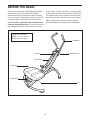
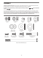
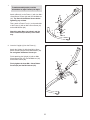
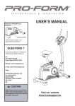
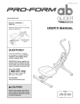
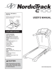
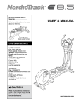
Model No. PFEVBE13710.2 Serial No. Write the serial number in the space above for reference. USER’S MANUAL Serial Number Decal QUESTIONS? If you have questions, or if there are missing parts, please contact us: UK Call: 08457 089 009 From Ireland: 053 92 36102 Website: www.iconsupport.eu E-mail: [email protected] Write: ICON Health & Fitness, Ltd. c/o HI Group PLC Express Way Whitwood, West Yorkshire WF10 5QJ, UK AUSTRALIA Call: 1-800-237-173 E-mail: [email protected] CAUTION Read all precautions and instructions in this manual before using this equipment. Keep this manual for future reference. www.iconeurope.com TABLE OF CONTENTS WARNING DECAL PLACEMENT . . . . . . . . . . . . . . . . . . . . . . . . . . . . . . . . . . . . . . . . . . . . . . . . . . . . . . . . . . . . . . .2 IMPORTANT PRECAUTIONS. . . . . . . . . . . . . . . . . . . . . . . . . . . . . . . . . . . . . . . . . . . . . . . . . . . . . . . . . . . . . . . . . . 3 BEFORE YOU BEGIN. . . . . . . . . . . . . . . . . . . . . . . . . . . . . . . . . . . . . . . . . . . . . . . . . . . . . . . . . . . . . . . . . . . . . . . .4 ASSEMBLY . . . . . . . . . . . . . . . . . . . . . . . . . . . . . . . . . . . . . . . . . . . . . . . . . . . . . . . . . . . . . . . . . . . . . . . . . . . . . . . .5 HOW TO USE THE ABDOMINAL EXERCISER. . . . . . . . . . . . . . . . . . . . . . . . . . . . . . . . . . . . . . . . . . . . . . . . . . . . 9 EXERCISE GUIDELINES. . . . . . . . . . . . . . . . . . . . . . . . . . . . . . . . . . . . . . . . . . . . . . . . . . . . . . . . . . . . . . . . . . . . 12 PART LIST. . . . . . . . . . . . . . . . . . . . . . . . . . . . . . . . . . . . . . . . . . . . . . . . . . . . . . . . . . . . . . . . . . . . . . . . . . . . . . . .14 EXPLODED DRAWING. . . . . . . . . . . . . . . . . . . . . . . . . . . . . . . . . . . . . . . . . . . . . . . . . . . . . . . . . . . . . . . . . . . . . .15 ORDERING REPLACEMENT PARTS . . . . . . . . . . . . . . . . . . . . . . . . . . . . . . . . . . . . . . . . . . . . . . . . . . . Back Cover WARNING DECAL PLACEMENT This drawing shows the location(s) of the warning decal(s). If a decal is missing or illegible, see the front cover of this manual and request a free replacement decal. Apply the decal in the location shown. Note: The decal(s) may not be shown at actual size. PROFORM is a registered trademark of ICON IP, Inc. 2 IMPORTANT PRECAUTIONS WARNING: To reduce the risk of serious injury, read all important precautions and instructions in this manual and all warnings on your abdominal exerciser before using your abdominal exerciser. ICON assumes no responsibility for personal injury or property damage sustained by or through the use of this product. 1. Before beginning any exercise program, consult your physician. This is especially important for persons over age 35 or persons with pre-existing health problems. 8. K eep children under age 12 and pets away from the abdominal exerciser at all times. 9. T he abdominal exerciser should not be used by persons weighing more than 300 lbs. (136 kg). 2. U se the abdominal exerciser only as described in this manual. 10.Wear appropriate clothes while exercising; do not wear loose clothes that could become caught on the abdominal exerciser. Always wear athletic shoes for foot protection while exercising. 3. It is the responsibility of the owner to ensure that all users of the abdominal exerciser are adequately informed of all precautions. 4. T he abdominal exerciser is intended for home use only. Do not use the abdominal exerciser in any commercial, rental, or institutional setting. 11.Use extreme caution while mounting and dismounting the abdominal exerciser (see HOW TO MOUNT AND DISMOUNT THE ABDOMINAL EXERCISER on page 9). Always hold the handlebar while exercising; do not hold the pivot frame or the console. 5. Keep the abdominal exerciser indoors, away from moisture and dust. Place the abdominal exerciser on a level surface, with carpet or a non-slip mat beneath it. 12.Keep hands and feet away from moving parts. 6. M ake sure that there is enough clearance around the abdominal exerciser to mount, dismount, and use the abdominal exerciser. 13.Over exercising may result in serious injury or death. If you feel faint or if you experience pain while exercising, stop immediately and cool down. 7. Inspect and properly tighten all parts regularly. Replace any worn parts immediately. 3 BEFORE YOU BEGIN Thank you for selecting the PROFORM® AB GLIDER abdominal exerciser. The versatile AB GLIDER abdominal exerciser is designed to help you develop your core muscles, improve your muscle tone, achieve a shapelier figure, and increase your overall fitness. of this manual. To help us assist you, note the product model number and serial number before contacting us. The model number and the location of the serial number decal are shown on the front cover of this manual. Before reading further, please review the drawing below and familiarize yourself with the labeled parts. For your benefit, read this manual carefully before using the abdominal exerciser. If you have questions after reading this manual, please see the front cover Length: 4 ft. (122 cm) Width: 2 ft. 6 in. (76 cm) Weight:53 lbs. (24 kg) Handlebar Console Handlebar Knob Pivot Frame Knee Pad Roller Stop Pin 4 ASSEMBLY Assembly requires two persons. Place all parts of the abdominal exerciser in a cleared area and remove the packing materials. Do not dispose of the packing materials until assembly is completed. In addition to the included tool(s), assembly requires a Phillips screwdriver wrench . and an adjustable As you assemble the abdominal exerciser, use the drawings below to identify small parts. The number in parentheses below each drawing is the key number of the part, from the PART LIST near the end of this manual. The number following the parentheses is the quantity needed for assembly. Note: If a part is not in the hardware kit, check to see if it has been preassembled. To avoid damaging parts, do not use power tools. M8 Locknut (46)–1 M10 Locknut (38)–1 M10 Curved Washer (39)–2 M4 x 16mm Screw (31)–2 M4 Washer (48)–2 Large Washer (41)–1 M6 x 15mm Button Screw (28)–4 M8 x 15mm Button Screw (29)–12 M10 x 157mm Button Bolt (30)–1 5 M6 Washer (35)–4 M8 Washer (34)–13 Pivot Washer (43)–1 M8 x 55mm Button Bolt (47)–1 1. 1 o make assembly easier, read the T information on page 5 before you begin. Attach a Base (2) to the Frame (1) with four M8 x 15mm Button Screws (29) and four M8 Washers (34). Tip: Start all the Button Screws before tightening any of them. 1 29 34 Then, attach a Frame Foot (11) to the underside of the Frame (1) with an M4 x 16mm Screw (31) and an M4 Washer (48). 29 34 2 Attach the other Base (not shown) and the other Frame Foot (not shown) in the same way. 11 48 31 2. Insert the Upright (4) into the Frame (1). 2 Attach the Upright (4) with three M8 x 15mm Button Screws (29) and three M8 Washers (34). Do not tighten the Button Screws yet. 4 inish attaching the Upright (4) with an M8 x F 55mm Button Bolt (47), two M8 Washers (34), and an M8 Locknut (46). 29 irmly tighten the three M8 x 15mm Button F Screws (29) and the M8 Locknut (46). 47 34 34 34 1 46 6 34 3.Attach the Handlebar (5) to the Upright (4) with an M10 x 157mm Button Bolt (30), two M10 Curved Washers (39), and an M10 Locknut (38). 3 Tip: It may be helpful to use a hex key to turn the M10 x 157mm Button Bolt (30) while you are inserting it through the Handlebar (5) and the Upright (4). 30 5 39 Secure the Handlebar (5) with the Handlebar Knob (37). 39 4 37 4.Using a small plastic bag to keep your hand clean, apply a small amount of the included grease to both sides of a Pivot Washer (43) and to the axle on the Pivot Frame (3). 4 Slide the Pivot Washer (43) onto the axle on the Pivot Frame (3). Then, insert the Pivot Frame into the Frame (1). 3 Attach the Pivot Frame (3) with an M8 x 15mm Button Screw (29) and a Large Washer (41). Do not overtighten the Button Screw; the Pivot Frame must pivot freely. Grease 43 1 41 29 7 38 5.Orient the Knee Pad (7) and the Roller Carriage (6) as shown. 5 Attach the Knee Pad (7) to the Roller Carriage (6) with four M6 x 15mm Button Screws (28) and four M6 Washers (35). 7 Wide End 6 Welded Bar 35 35 28 28 6.Orient the Roller Carriage (6) as shown. Slide the Roller Carriage onto the Pivot Frame (3). 6 3 16 Tighten the Roller Stop (16) into the Pivot Frame (3). Welded Bar 7.Move the Roller Carriage (6) to the position shown, and align the indicated hole in the Roller Carriage with the corresponding hole (not shown) in the Pivot Frame (3). 6 7 Insert the Pin (27) into the Roller Carriage (6) and the Pivot Frame (3). Hole 3 6 27 8. M ake sure that all parts are properly tightened before you use the abdominal exerciser. Note: Some hardware may be left over after assembly is completed. 8 HOW TO USE THE ABDOMINAL EXERCISER HOW TO MOUNT AND DISMOUNT THE ABDOMINAL EXERCISER HOW TO LOCK THE PIVOT FRAME To lock the Pivot Frame (3) so that it will not swivel from side to side, insert the Pin (27) into the Pivot Frame and into the Upright (4). The pivot frame can swivel from side to side, and the knee pad can move forward and backward; to avoid losing your balance, use extreme caution while mounting and dismounting the abdominal exerciser. 27 Before mounting the abdominal exerciser, make sure that the Pivot Frame (3) is in the position shown below. Do not rotate the Pivot Frame so that the Console (8) is near the floor as shown in the inset drawing. 3 4 5 8 7 3 HOW TO LOCK THE KNEE PAD To lock the Knee Pad (7) so that it will not move forward and backward, insert the Pin (27) into the Roller Carriage (6) and into the Pivot Frame (3). 3 8 7 Next, stand beside the abdominal exerciser and hold the Handlebar (5) firmly with both hands. Place one knee on the Knee Pad (7), halfway between the front of the Knee Pad and the back of the Knee Pad. Then, place your other knee on the Knee Pad. Always hold the Handlebar while exercising; do not hold the Pivot Frame or the Console (8). 27 3 To dismount, hold the Handlebar (5) and place one foot at a time on the floor beside the Knee Pad (7). 9 6 HOW TO USE THE ABDOMINAL EXERCISER HOW TO STORE THE ABDOMINAL EXERCISER The abdominal exerciser can be used with the pivot frame in the locked position or the unlocked position (see HOW TO LOCK THE PIVOT FRAME on page 9). In addition, the abdominal exerciser can be used with the knee pad in the locked position or in the unlocked position (see HOW TO LOCK THE KNEE PAD on page 9). The abdominal exerciser can be folded for storage. First, remove the Pin (27) if necessary. Next, remove the Roller Stop (16), and slide the Knee Pad (7) off the Pivot Frame (3). 5 With the pivot frame unlocked and the knee pad unlocked, the pivot frame can swivel from side to side and the knee pad can move forward and backward. To exercise, use your core muscles to swivel the pivot frame from side to side and/or to move the knee pad forward and backward. 3 Wide End With the pivot frame locked and the knee pad unlocked, the pivot frame will not swivel from side to side, but the knee pad will move forward and backward. To exercise, use your core muscles to move the knee pad forward and backward. 7 37 16 27 With the pivot frame unlocked and the knee pad locked, the pivot frame can swivel from side to side, but the knee pad will not move forward and backward. To exercise, use your core muscles to swivel the pivot frame from side to side. Then, remove the Handlebar Knob (37), swivel the Pivot Frame (3) to the right or to the left, and fold the Handlebar (5) downward. For more information about using the abdominal exerciser, see the accompanying workout DVD. Reverse these actions to reassemble the abdominal exerciser. Make sure to orient the Knee Pad (7) as shown. 10 FEATURES OF THE CONSOLE HOW TO USE THE CONSOLE The console features five modes that provide instant exercise feedback during your workouts: Note: Make sure that a battery is installed (see HOW TO INSTALL A BATTERY at the left). If there is a sheet of plastic on the display, remove the plastic. Scan—Displays the Time, Calorie, and Reps/Min modes in a repeating cycle 1. Turn on the console. Press the console button on the console or begin exercising to turn on the console. Time—Displays the elapsed time 2. Select a mode for display. Count—Displays the number of repetitions completed during the current workout Calorie—Displays the approximate number of calories you have burned Reps/Min—Displays the number of repetitions completed per minute Scan mode—To select the scan mode, press the console button repeatedly until an arrow appears next to the word SCAN. Time, Calorie, or Reps/Min mode—To select one of these modes for continuous display, press the console button repeatedly until an arrow appears next to the desired selection. Make sure that there is not an arrow next to the word SCAN. HOW TO INSTALL A BATTERY The console requires one AAA battery (not included); an alkaline battery is recommended. IMPORTANT: If the console has been exposed to cold temperatures, allow it to warm to room temperature before you insert a battery. Otherwise, you may damage the console display or other electronic components. 3.Begin exercising and follow your progress with the display. As you exercise, the console will provide instant feedback about your workout. 4. Reset the console, if desired. Locate the battery door on the back of the console. Press the tab on the battery door, and remove the battery door. Next, insert a battery into the console; orient the battery as shown by the diagram inside the console. Then, reattach the battery door. To reset the console display, press and hold the console button for several seconds until zeros appear in the display. 5.When you are finished exercising, the console will turn off automatically. If you do not move the knee pad and do not press the console button for a few minutes, the console will turn off automatically. 11 EXERCISE GUIDELINES Aerobic Exercise—If your goal is to strengthen your cardiovascular system, you must perform aerobic exercise, which is activity that requires large amounts of oxygen for prolonged periods of time. For aerobic exercise, adjust the intensity of your exercise until your heart rate is near the highest number in your training zone. WARNING: Before beginning this or any exercise program, consult your physician. This is especially important for persons over age 35 or persons with pre-existing health problems. HOW TO MEASURE YOUR HEART RATE These guidelines will help you to plan your exercise program. For detailed exercise information, obtain a reputable book or consult your physician. Remember, proper nutrition and adequate rest are essential for successful results. To measure your heart rate, exercise for at least four minutes. Then, stop exercising and place two fingers on your wrist as shown. Take a six-second heartbeat count, and multiply the result by 10 to find your heart rate. For example, if your six-second heartbeat count is 14, your heart rate is 140 beats per minute. EXERCISE INTENSITY Whether your goal is to burn fat or to strengthen your cardiovascular system, exercising at the proper intensity is the key to achieving results. You can use your heart rate as a guide to find the proper intensity level. The chart below shows recommended heart rates for fat burning and aerobic exercise. WORKOUT GUIDELINES Warming Up—Start with 5 to 10 minutes of stretching and light exercise. A warm-up increases your body temperature, heart rate, and circulation in preparation for exercise. Training Zone Exercise—Exercise for 20 to 30 minutes with your heart rate in your training zone. (During the first few weeks of your exercise program, do not keep your heart rate in your training zone for longer than 20 minutes.) Breathe regularly and deeply as you exercise—never hold your breath. To find the proper intensity level, find your age at the bottom of the chart (ages are rounded off to the nearest ten years). The three numbers listed above your age define your “training zone.” The lowest number is the heart rate for fat burning, the middle number is the heart rate for maximum fat burning, and the highest number is the heart rate for aerobic exercise. Cooling Down—Finish with 5 to 10 minutes of stretching. Stretching increases the flexibility of your muscles and helps to prevent post-exercise problems. EXERCISE FREQUENCY Burning Fat—To burn fat effectively, you must exercise at a low intensity level for a sustained period of time. During the first few minutes of exercise, your body uses carbohydrate calories for energy. Only after the first few minutes of exercise does your body begin to use stored fat calories for energy. If your goal is to burn fat, adjust the intensity of your exercise until your heart rate is near the lowest number in your training zone. For maximum fat burning, exercise with your heart rate near the middle number in your training zone. To maintain or improve your condition, complete three workouts each week, with at least one day of rest between workouts. After a few months of regular exercise, you may complete up to five workouts each week, if desired. Remember, the key to success is to make exercise a regular and enjoyable part of your everyday life. 12 SUGGESTED STRETCHES The correct form for several basic stretches is shown at the right. Move slowly as you stretch—never bounce. 1. Toe Touch Stretch Stand with your knees bent slightly and slowly bend forward from your hips. Allow your back and shoulders to relax as you reach down toward your toes as far as possible. Hold for 15 counts, then relax. Repeat 3 times. Stretches: Hamstrings, back of knees and back. 1 2. Hamstring Stretch Sit with one leg extended. Bring the sole of the opposite foot toward you and rest it against the inner thigh of your extended leg. Reach toward your toes as far as possible. Hold for 15 counts, then relax. Repeat 3 times for each leg. Stretches: Hamstrings, lower back and groin. 2 3. Calf/Achilles Stretch With one leg in front of the other, reach forward and place your hands against a wall. Keep your back leg straight and your back foot flat on the floor. Bend your front leg, lean forward and move your hips toward the wall. Hold for 15 counts, then relax. Repeat 3 times for each leg. To cause further stretching of the achilles tendons, bend your back leg as well. Stretches: Calves, achilles tendons and ankles. 3 4 4. Quadriceps Stretch With one hand against a wall for balance, reach back and grasp one foot with your other hand. Bring your heel as close to your buttocks as possible. Hold for 15 counts, then relax. Repeat 3 times for each leg. Stretches: Quadriceps and hip muscles. 5. Inner Thigh Stretch Sit with the soles of your feet together and your knees outward. Pull your feet toward your groin area as far as possible. Hold for 15 counts, then relax. Repeat 3 times. Stretches: Quadriceps and hip muscles. 13 5 PART LIST Model No. PFEVBE13710.2 R0312A Key No. Qty. Description Key No. Qty. Description 1 2 3 4 5 6 7 8 9 10 11 12 13 14 15 16 17 18 19 20 21 22 23 24 25 26 27 Frame Base Pivot Frame Upright Handlebar Roller Carriage Knee Pad Console Pivot Cover Base Foot Frame Foot Bumper Pivot Frame Cap Upper Handlebar Cap Upright Cap Roller Stop Foam Grip Reed Switch/Wire Upper Roller Lower Roller Roller Carriage Cap Long Magnet Bracket Short Magnet Bracket Console Screw Roller Spacer M4 x 12mm Screw Pin 28 29 30 31 32 33 34 35 36 37 38 39 40 41 42 43 44 45 46 47 48 49 50 * • * * M6 x 15mm Button Screw M8 x 15mm Button Screw M10 x 157mm Button Bolt M4 x 16mm Screw Roller Axle M4 x 20mm Screw M8 Washer M6 Washer M10 Washer Handlebar Knob M10 Locknut M10 Curved Washer Bushing Large Washer Lower Handlebar Cap Pivot Washer Base Cap M13 Washer M8 Locknut M8 x 55mm Button Bolt M4 Washer M5 Washer M5 x 16mm Screw Assembly Tool Grease Packet DVD User’s Manual 1 2 1 1 1 1 1 1 1 4 2 2 1 2 1 1 2 1 2 2 2 1 1 3 4 1 1 4 12 1 15 2 2 13 4 6 1 3 2 2 1 2 1 4 2 5 1 10 2 2 – – – – Note: Specifications are subject to change without notice. For information about ordering replacement parts, see the back cover of this manual. *These parts are not illustrated. 14 EXPLODED DRAWING Model No. PFEVBE13710.2 R0312A 7 46 46 36 32 36 14 32 31 6 35 25 35 19 25 36 28 46 28 8 25 19 45 25 21 36 21 9 46 49 50 24 22 20 36 12 38 36 18 20 16 31 43 34 46 40 41 34 11 48 31 29 48 31 44 2 10 48 31 5 49 39 47 44 42 37 48 31 15 34 10 48 48 34 26 34 39 2 23 29 10 15 34 1 29 44 31 29 40 27 31 33 4 45 13 30 24 3 17 29 11 48 31 31 29 34 44 10 48 31 38 ORDERING REPLACEMENT PARTS To order replacement parts, please see the front cover of this manual. To help us assist you, be prepared to provide the following information when contacting us: • the model number and serial number of the product (see the front cover of this manual) • the name of the product (see the front cover of this manual) • the key number and description of the replacement part(s) (see the PART LIST and the EXPLODED DRAWING near the end of this manual) Part No. 328713 R0312A Printed in China © 2012 ICON IP, Inc.