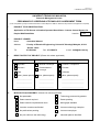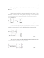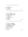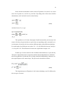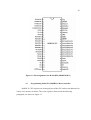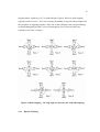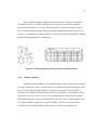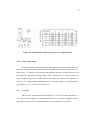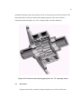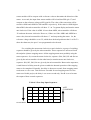
1
Lampiran 20 UTM/RMC/F/0024 (1998) UNIVERSITI TEKNOLOGI MALAYSIA BORANG PENGESAHAN LAPORAN AKHIR PENYELIDIKAN TAJUK PROJEK : APPLICATION OF TILT SENSOR IN HEADSET OPERATED SURVEILANCE CAMERA CONTROL SYSTEM FOR PEOPLE WITH DISABILITIES Saya ANITA BINTI AHMAD (HURUF BESAR) Mengaku membenarkan Laporan Akhir Penyelidikan ini disimpan di Perpustakaan Teknologi Malaysia dengan syarat-syarat kegunaan seperti berikut : Universiti 1. Laporan Akhir Penyelidikan ini adalah hakmilik Universiti Teknologi Malaysia. 2. Perpustakaan Universiti Teknologi Malaysia dibenarkan membuat salinan untuk tujuan rujukan sahaja. 3. Perpustakaan dibenarkan membuat penjualan Penyelidikan ini bagi kategori TIDAK TERHAD. 4. * Sila tandakan ( / ) salinan Laporan Akhir SULIT (Mengandungi maklumat yang berdarjah keselamatan atau Kepentingan Malaysia seperti yang termaktub di dalam AKTA RAHSIA RASMI 1972). TERHAD (Mengandungi maklumat TERHAD yang telah ditentukan oleh Organisasi/badan di mana penyelidikan dijalankan). TIDAK TERHAD TANDATANGAN KETUA PENYELIDIK Nama & Cop Ketua Penyelidik Tarikh : 10 NOVEMBER 2006 CATATAN : * Jika Laporan Akhir Penyelidikan ini SULIT atau TERHAD, sila lampirkan surat daripada pihak berkuasa/organisasi berkenaan dengan menyatakan sekali sebab dan tempoh laporan ini perlu dikelaskan sebagai SULIT dan TERHAD. Lampiran 13 UTM/RMC/F/0014 (1998) UNIVERSITI TEKNOLOGI MALAYSIA Research Management Centre PRELIMINARY IP SCREENING & TECHNOLOGY ASSESSMENT FORM (To be completed by Project Leader submission of Final Report to RMC or whenever IP protection arrangement is required) 1. PROJECT TITLE IDENTIFICATION : Application of Tilt Sensor in Headset Operated Surveillance Camera Control System for People With Disabilities 2. Vote No: 75226 PROJECT LEADER : Name : Anita binti Ahmad Address : Faculty of Electrical Engineering, Universiti Teknologi Malaysia, 81310 Skudai Johor Tel 3. : 07-5535326 Fax : 07-5566272 e-mail : [email protected] DIRECT OUTPUT OF PROJECT (Please tick where applicable) Secientific Research Applied Research Algorithm Method/Technique Product / Component Demonstration / Process Structure Product/Process Development Prototype Data Other, please specify 4. Software Other, please specify Other, please specify ___________________ __________________ ___________________________ ___________________ __________________ ___________________________ ___________________ __________________ ___________________________ INTELLECTUAL PROPERTY (Please tick where applicable) Not patentable Technology protected by patents Patent search required Patent pending Patent search completed and clean Monograph available Invention remains confidential Inventor technology champion No publications pending Inventor team player No prior claims to the technology Industrial partner identified 1 UTM/RMC/F/0014 (1998) 5. LIST OF EQUIPMENT BOUGHT USING THIS VOT -Nil 6. 7. STATEMENT OF ACCOUNT a) APPROVED FUNDING RM : ……-…………………… b) TOTAL SPENDING RM : ……-…………………… c) BALANCE RM : ……-…………………… TECHNICAL DESCRIPTION AND PERSPECTIVE Please tick an executive summary of the new technology product, process, etc., describing how it works. Include brief analysis that compares it with competitive technology and signals the one that it may replace. Identify potential technology user group and the strategic means for exploitation. a) Technology Description It focuses on the invention of a head-set operated device to control the movement of the camera, such that the camera can turn left and right according to the movement of the human head. It employs one tilt sensor, which placed in the headset to determine head position and to function as simple headset control system. The tilt sensor detects the lateral head motion to drive the left or right displacement of the camera. This system was invented to assist people with disabilities to live an independent life or even allow them to work as security personnel to earn their life. The idea can be employed in other application such as robotics, intelligent home devices and vehicle control as well. b) Market Potential For security company. 2 UTM/RMC/F/0014 (1998) c) Commercialisation Strategies We have contacted some security company and still discussing the potential of this research in their company. 8. RESEARCH PERFORMANCE EVALUATION a) FACULTY RESEARCH COORDINATOR Research Status Spending Overall Status ( ) ( ) ( ) ( ) ( ) ( ) Excellent Very Good ( ) ( ) ( ) ( ) ( ) ( ) Good Satisfactory ( ) ( ) ( ) Fair ( ) ( ) ( ) Weak Comment/Recommendations : _____________________________________________________________________________ _____________________________________________________________________________ _____________________________________________________________________________ _____________________________________________________________________________ _____________________________________________________________________________ _____________________________________________________________________________ ………………………………………… Signature and stamp of JKPP Chairman Name : ……………………………………… Date 3 : ……………………………………… UTM/RMC/F/0014 (1998) RE b) RMC EVALUATION Research Status Spending Overall Status ( ) ( ) ( ) ( ) ( ) ( ) ( ) ( ) ( ) Excellent Very Good Good ( ) ( ) ( ) ( ) ( ) ( ) ( ) ( ) ( ) Satisfactory Fair Weak Comments :_____________________________________________________________________________ _____________________________________________________________________________ _____________________________________________________________________________ _____________________________________________________________________________ _____________________________________________________________________________ _____________________________________________________________________________ Recommendations : Needs further research Patent application recommended Market without patent No tangible product. Report to be filed as reference ……………………………………….. Name : …………………………………………… Signature and Stamp of Dean / Deputy Dean Research Management Centre Date : …………………………………………… 4 ABSTRACT Owing to the lack of appropriate assistive devices, people with disabilities often encounter several obstacles when going through their life. This project describes the motivation and design considerations of an economical head operated surveillance camera for people with disabilities. In addition, it focuses on the invention of a head-set operated device to control the movement of the camera, such that the camera can turn left and right according to the movement of the human head. It employs one tilt sensor, which placed in the headset to determine head position and to function as simple headset control system. The tilt sensor detects the lateral head-motion to drive the left or right displacement of the camera. A touch switch device was deployed to contact gently with operator’s cheek to give special signal when the operator saw some suspected scenery from the camera. Operator may puff his cheek to trigger the device to perform such function. The signal from sensor is converted to digital signal by Analogue to Digital Converter. This digital signal will enable the microcontroller to perform simple control algorithm to drive the stepper motor to turn the camera accordingly. This system was invented to assist people with disabilities to live an independent life or even allow them to work as security personnel to earn their life. The idea can be employed in other applications such as robotics, intelligent home devices and vehicles control as well. ABSTRAK Orang cacat sentiasa menghadapi halangan dalam kehidupan harian mereka disebabkan oleh kekurangan alat pembantu yang sesuai. Projek ini membincangkan motivasi dan reka bentuk satu sistem kawalan kamera berpandukan kepala manusia yang ekonomi untuk orang cacat.. Di samping itu, ia fokus kepada ciptaan satu headset yang boleh mengawal gerakan kamera seperti putaran ke kiri atau ke kanan mengikut pergerakan kepala manusia. Ia menggunakan satu senser tilt yang diletakkan di headset untuk mengenalpasti posisi kepala manusia dan sebagai satu sistem kawalan berpanduan headset. Senser tilt ini mengesan pergerakkan kepala bagi menggerakkan kamera ke kiri atau ke kanan. Satu suis sentuhan juga digunakan untuk sentuh dengan muka pengguna bagi memberi isyarat apabila pengguna ternampak sesuatu yang disyaki daripada gambaran oleh kamera. Pengguna boleh menggerakkan anak muka mereka untuk membolehkan suis sentuh untuk menjalankan fungsi tersebut. Isyarat daripada senser akan ditukarkan ke isyarat digital oleh Penukar Analog ke Digital. Isyarat digital tersebut akan membolehkan mikrocontroller untuk menjalankan algorithm kawalan bagi motor pelankah memusing kamera. Sistem ini direka bagi membantu orang cacat berdikari dalam kehidupan dan seterusnya membolehkan mereka berkerja sebagai pegawai keselamatan demi mencari rezeki bagi kehidupan mereka. Idea ini juga boleh di gunakan dalam apikasi yang lain seperti dalam robotik, alatan rumah yang pintar dan kawalan kenderaan. CONTENTS CHAPTER TITLE PAGE ABSTRACT ABSTRAK CONTENTS LIST OF TABLES LIST OF FIGURES I II INTRODUCTION 1 1.1 Introduction 1 1.2 Objectives of the Project 3 1.3 Scope of the Project 4 1.4 Organization of the Thesis 4 BASIC CONCEPT OF A TILT SENSOR 5 2.1 Basic Concept 5 2.2 Characteristics Of Tilt Sensor 7 2.3 Dual-Axis Tilt Sensor 8 III 2.4 Sensor Selection 11 2.5 Sensor Calibrations 13 2.6 Calculations For Finding Right Angle 14 APPLICATION NOTES ON 21 MICROCONTROLLER 3.1 Basic Concept Of Microcontroller 21 3.2 System Architecture Of 22 M68HC11 Series 3.3 Programming Model For 24 M68HC11 Microcontroller 3.4 Operating Modes And On-Chip 26 Memory IV 3.5 Electric Erase Programmable ROM 28 3.6 Analog To Digital Converter In 68HC11 29 APPLICATION NOTES ON USED STEPPING 33 MOTOR 4.1 Basic Concept Of Stepping Motor 33 4.1.1 Full Step 33 4.1.2 Half Stepping 35 4.1.3 Bipolar Winding 36 4.1.4 Unipolar Winding 37 4.1.5 Others Step Angles 38 4.2 Accuracy 38 4.3 Resonance 39 4.4 Torque 40 4.5 Linear Actuators 41 4.6 AC Synchronous Motors 44 4.7 Drivers 44 4.7.1 Bipolar Drive 45 4.7.2 Unipolar Drive 45 4.7.3 Inductance To Resistance 45 (L/R) Drives 4.8 V 4.7.4 Chopper Drives 46 4.7.5 Microstepping Drives 46 Used Stepping Motor 46 PEOPLE WITH DISABILITIES 49 5.1 Introduction 49 5.2 Successful Disable People 49 5.3 Spinal Cord Injuries 51 5.3.1 Definition 51 5.3.2 Spinal Cord 51 5.3.3 The Effects Of Spinal Cord 53 Injuries 5.3.4 The Cure Of The Injuries 55 5.3.5 The Life Of A Injured People 55 5.3.6 The Length Of Life For The 56 SCI Patients 5.4 Statistics About The Disable People 57 5.4.1 Statistics In Malaysia 58 5.4.2 Statistics About SCI in 59 United State VI HARDWARE DEVELOPMENT AND CIRCUITS DESIGN 63 6.1 Project Overview 63 6.2 Sensor Module 64 6.2.1 Sensor Selection 65 6.2.2 Sensor Converter Circuits 66 6.3 Controller Module 68 6.3.1 Hardware Design 69 6.3.2 Software Programming 72 6.4 Switching Module 77 6.5 Surveillance Camera 79 VII RESULTS 81 VIII CONCLUSION AND RECOMMENDATION 85 8.1 Conclusion 85 8.2 Problems 85 8.3 Future Development And 86 Recommendation IX REFERENCES 88 LIST OF TABLES NO. TABLES 3.1 TITLE Input for MODA and MODB pins PAGE 27 and its Operating Mode 5.1 Life expectancy (years) for post-injury 62 by severity of injury and age at injury 6.1 DC voltage output of the sensor module 67 circuits 6.2 Codes for showing alphabets 70 6.3 Four Step Input Sequences 73 LIST OF FIGURES NO. FIGURES 2.1 TITLE Single-axis view of a five-pin, fluid-filled PAGE 6 tilt sensor in the upright position shows the physical relationship among the vial, pins and fluids when the sensor is slightly tilted 2.2 The arrows indicate the direction of 9 current flow that occurs when voltage waveforms apply simultaneous excitation to four outer pins 2.3 Hardware and firmware functions are 10 performed by a high-end, microprocessor-based, dual-axis inclinometer 2.4 Tilt sensor signal plotted against the 11 ideal tangent response, note that above 20° the signal output becomes nonlinear and requires calibration 3.1 M68HC11 E-series block diagram 23 3.2 Pin Assignments for 48-Pin DIP 24 (M68HC811E2) 3.3 Programming Model For M68HC11 25 E Series 3.4 The Flow of Programming M68HC11 25 E Series 3.5 Memory Map for MC68HC11E0, 28 MC68HC11E1, MC68HC11E8, and MC68HC(7)11E9 3.6 Electrical Model of an A/D Input 30 Pin (Sample Mode) 3.7 A/D Converter Block Diagram 31 3.8 A/D Conversion Sequence 32 4.1 Magnetic field created by energizing 33 a coil winding 4.2 “One phase on” stepping sequence 34 for two phase motor 4.3 “Two phase on” stepping sequence 35 for two phases motor 4.4 Half-stepping – 90° step angle is 36 reduced to 45° with half-stepping 4.5 Wiring diagram and step sequence 37 for bipolar motor 4.6 Wiring diagram and step sequence 38 for unipolar motor 4.7 Partial cut away showing pole plates 39 of a 7.5° step angle motor 4.8 Frictional torque is the force (F) 41 required to move a load multiplied by the length of the lever arm (r) 4.9 Linear Actuators, left to right: (3/4” Ø), 42 captive shaft (1” Ø) non-captive, and (1.4” Ø) captive 4.10. Linear actuator cut away showing 43 threaded rotor to lead screw interface 4.11 The Connection Between Each 47 Phase Wire 5.1 Spinal Cord and its surrounding bones 53 5.2 Human Vertebrate With Spinal Cord 54 5.3 Number of Rehabilitation Center in 58 Malaysia 5.4 Number of Inmates in Each Center 59 5.5 Etiology of SCI since 1990 61 6.1 Head-set Control System 64 6.2 System Architecture 64 6.3 0717-4304-99 “MCL” Dual Axis, 66 Wide Angle, Electrolytic Tilt Sensor 6.4 AC To DC Conversion Circuits 68 6.5 Voltage Divider Circuits Give 5V and 1V 70 6.6 7-segment Display 71 6.7 Controller Module Circuits 72 6.8 Program Flow Chart 74 6.9 The connection of MAX 232C and 75 DS275 for communication between PC and Microcontoller chip 6.10 PCBUG11 76 6.11 Mini IDE version 1.14 by MGTEK 77 6.12 Motor Switching Circuits 78 6.13 Logitech QuickCam® 79 6.14 QuickCam Version 6.0SE 80 7.1 Head-set Operated Surveillance Camera 82 Control System 7.2 User With The Head-Set Operated 82 Control System 7.3 Controller Module 83 7.4 Motor Switching Module 83 7.5 Connection Between The Modules 84 CHAPTER 1 INTRODUCTION 1.1 Introduction Owing to the lack of appropriate input devices, people with disabilities often encounter several obstacles when going through their life. People with spinal cord injuries (SCIs) and who are paralyzed have increasingly applied electronic assistive devices to improve their ability to perform certain essential functions. Electronic equipment, which has been modified to benefit people with disabilities include communication and daily activity devices, computers and powered wheelchairs. A wide range of interfaces is available between the user and the device. These interfaces can be an enlarged computer keyboard or a complex system that allows the user to operate or control a movement with the aid of a mouthstick, an eye imaged input system, electroencephalogram (EEG) signals and an infrared or ultrasound-controlled mouse system (origin instruments’ headmouse and prentke romish’s head master) and etc. However, for many people the mouthstick method is not 2 accurate and comfortable to use. Likewise, the eye movement and the EEG methods are capable of providing only a few controlled movements, have slow response time for signal processing and require substantial motor coordination. Within the infrared or ultrasound-controlled computer mouse, there are two primary determinants that are of concern to the user. The first one being whether the transmitter is designed to aim at an effective range or not with respect to receiver, the other one being whether the cursor of computer mouse can move with his head or not. These considerations increase the load for people with disabilities. Thus, alternative systems that utilize commercially available electronics to perform tasks with easy operation and easy interface control are sorely required. The ability to operate motor powered devices has become increasingly important to people with disabilities, especially as the advancement of technology allows more and more functions to be controlled by an electric powered motor. There are many reasons for people with disabilities to operate an electric powered motor. For instance, they need to control the wheel chair, which is moved by the motored wheels. Besides, with more and more robotics technology applied in modern home, they need to control the movement of the mobile robots, which can help them to perform many jobs in their living place. Further more, there are many automated electronics devices, which are operated by electric powered motor in this modern world in offices, factories and at home. Therefore, there is an urgent need to develop a practical and economic method to help people with disabilities in going through their daily life. This research focuses on the design of a tilt sensor-controlled headset control system for patients who are quadriplegic from a cervical cord injury and have retained the ability to rotate the neck. The tilt sensors or inclinometers detect the angle between a sensing axis and a reference vector such as gravity or the earth’s magnetic field. In the area of medicine science, tilt sensors have been used mainly in occupational medicine research. For example, application of sensors in gait analysis is currently being investigated. Otun and Anderson employed a tilt sensor to continuously measure the 3 sagittal movement of the lumbar spine. Andrews et al. used tilt sensors attached to a floor reaction type ankle foot orthosis as a biofeedback source via an electrocutaneous display to improve postural control during functional electrical stimulation (FES) standing. Bowker and Heath recommended using a tilt sensor to synchronize peroneal nerve stimulation to the gait cycle of hemiplegics by monitoring angular velocity. Basically, tilt sensors have potential applications of improving the abilities for persons with other disabilities. As stated, the study presents a head-operated control system that uses tilt sensors placed in the headset to determine user’s head position and to function as a simple head-operated control system for surveillance camera. The tilt sensors can sense the operator’s head motion up, down, left, and right, etc. Accordingly, the motor that was employed to move the camera direction can be determined. 1.2 Objectives of the Project The main motivation for this project is to help the disabilities people to live a better life. With a practical way to control the motor, it can help them to perform many simple activities in their daily life. With surveillance camera installed on the motor, it can help them to operate the camera and further more to enable them to view their surrounding and further more to gain a job as security personnel and earn their life. Besides, the project also aims to design and develop the device to enable the people with disabilities, especially those with Spinal Cord Injuries (SPI) and paralyzed to enhance their quality of life. On the other hand, the project also provide the opportunities to study the alternative ways to control the electric powered motor by tilt sensor and microcontroller. This method can be applied in other applications such as virtual robotics control, medical operation applications, home devices applications and etc. 4 1.3 Scope of the Project 1. To understand the function and the operation of various tilt sensors. 2. To study the application of the microcontroller and its feasibility for the projects. 3. To understand the operation of a stepper motor and the ways to use an used unipolar stepping motor. 4. To design the prototype of the sensor module, controller module and motor switching module. 5. To develop a practical way to enable the people with disabilities to control the movement of the motor. 1.4 Organization of the Thesis This thesis consists of 8 chapters as below: 1. Introduction. 2. Basic concept of a tilt sensor. 3. Application notes on a Motolora M68HC11 microcontroller. 4. Concepts and application notes on an used stepping motor. 5. People with disabilities- Spinal Cord Injuries. 6. Design and development of the project. 7. Results of the projects. 8. Conclusion and Recommendation. 5 CHAPTER 2 BASIC CONCEPT OF A TILT SENSOR 2.1 Basic Concept Electrolytic tilt sensors are capable of producing extremely accurate pitch and roll measurements in a variety of applications. They provide excellent repeatability, stability, and accuracy when operating at low frequencies, and come in a variety of packages with varying tilt range and resolution. These rugged, passive devices can be used in environments of extreme temperature, humidity, and shock. Sensors may vary in height, pin spacing, electrolyte volume and composition, and pin and glass treatment, so there are many possible combinations of attributes for each model of sensor. To properly evaluate an electrolytic tilt sensor, its performance should be tested in conditions that closely reflect the end product's actual operating environment. Normally, vendors have Signal Conditioning Boards that can be used to interface the sensor to a host product. Both analog and microprocessor-based modules are offered. The signal conditioning board excites the sensor and provides a linearized analog or digital output to the host. Typically, a regulated DC power source is required, and provision is made for offset and gain adjustments. The board must be carefully 6 aligned in order to provide accurate test results. However, these boards are very expensive. As the sensor tilts, the surface of the fluid remains level due to gravity. The fluid is electrically conductive, and the conductivity between the two electrodes is proportional to the length of electrode immersed in the fluid. At the angle shown, for example, the conductivity between pins a and b would be greater than that between b and c (Please refer to figure 2.1). Electrically, the sensor is similar to a potentiometer, with resistance changing in proportion to tilt angle. Figure 2.1 shows one axis of a fluidfilled sensor tipped at 15°. Figure 2.1 Single-axis view of a five-pin, fluid-filled tilt sensor in the upright position shows the physical relationship among the vial, pins and fluids when the sensor is slightly tilted. However, user can't just attach the sensor to a 6 V battery and expect it to work. The sensor is an electrolytic cell that functions somewhat similarly to a lead acid battery, but in reverse. Instead of converting chemical energy into electricity, a direct electric current induces a chemical reaction--electrolysis--in the fluid. Positive ions in the fluid 7 migrate to the cathode, where they combine with excess electrons and lose some of their charge. Likewise, negative ions in the fluid propagate to the anode and combine with excess protons to lose their charge. If allowed to proceed, the reaction will eventually render the fluid nonconductive. To prevent electrolysis, alternating current must be used to excite the sensor. The required frequency and symmetry of the AC waveform depend on the chemistry of the fluid and composition of the electrodes. The frequency must be high enough so that the process described above is reversible. For some electrolytes this frequency can be as low as 25 Hz. Other solutions require a minimum of 1000 Hz to 4000 Hz. 2.2 Characteristics Of Tilt Sensor There are a few other, less pernicious characteristics of the electrolytic fluid that are important to understand: a. Total conductance varies with both temperature and tilt angle. Therefore, a measurement technique that is insensitive to total conductance is required to precisely determine the tilt angle. Sensor manufacturers can control what they call the null impedance at room temperature by changing the volume and chemical composition of the fluid. The extent to which the impedance varies with temperature and tilt depends on the physical properties of the fluid and the geometry of the device. Impedance can typically change by a factor of 20 or more over temperature and tilt. b. The sensor's angle range is a function of the volume of fluid, electrode spacing, and electrode height. Provided that the electrodes and container are tall enough not to be limiting factors, tilt measurement range is proportional to fluid volume. Because the volume of a liquid is proportional to its temperature, the overall gain, or scale factor, of the device is also proportional to temperature. If this 8 effect is large enough to be significant, the measurement circuitry must compensate by varying gain inversely with temperature. c. The fluid may need to settle after a sudden jolt, so the measurement does not always indicate the sensor's true attitude. Manufacturers can add damping agents that change the fluid's viscosity without affecting its conductance, but these work best to filter out high-frequency vibration in an otherwise stable measurement environment. Higher viscosity can also reduce repeatability, especially at high angles, due to interaction between the fluid and its container. As previously noted, scale factor is proportional to fluid volume, and since the fluid clinging to the wall is not part of the volume interacting with the electrodes, the measurement will change depending on the extent of surface wetting. 2.3 Dual-Axis Tilt Sensor With the advancement of manufacturing techniques, dual-axis sensors exhibit the same fluid characteristics as single-axis devices--but have the added complexity of interaction between the axes. Both axes share the center electrode. The four outer electrodes are ideally placed at the four corners of a perfect square. Misalignment between electrodes gives rise to cross-axis coupling that can result in significant errors. There are at least two techniques that can be used to derive independent measurements for each axis. The first is to excite only one axis at a time, alternating between pitch and roll at an appropriate rate. In this case, the excitation must be completely disconnected from one axis while the other is being driven. Leakage to the disconnected side will adversely affect the active measurement. A second technique requires two excitation frequencies, one twice the other. Here, all four pins are driven simultaneously, and the phase of the excitation determines which axis is being measured. . Figure 2.2 shows the waveforms applied to outer 9 electrode pins a, c, d, and e. Beneath the waveforms, the diagrams indicate the direction of current flow through the sensor. Figure 2.2 The arrows indicate the direction of current flow that occurs when voltage waveforms apply simultaneous excitation to four outer pins Note that when using the first technique, the two orthogonal axes are along the diagonals a–c and d–e, while in the second method the two axes are aligned with the edges of the square formed by the outer electrodes. This gives rise to a small difference in sensitivity (change in signal per degree tilt) and range between the two techniques. It also requires either a physical rotation of the sensor or an electronic rotation of the axes to equate pitch and roll measurements. A significant advantage of the four-phase drive is its simplicity. It can easily be implemented in hardware, entailing neither microcontroller overhead nor critical timing functions. Low-leakage switches are not required, and there are several ways that the signal from the center electrode can be processed to yield pitch and roll measurements. The alternating axis drive requires less power and may be easier to switch on and off so that the sensor is excited only when a measurement is needed. Since the 10 measurement axes are along the diagonals, the signal is slightly more sensitive to tilt, which is generally advantageous.Figure 2. 3 shows the major functional elements of a high-end, microprocessor-based, dual-axis tilt meter. Figure 2.3 Hardware and firmware functions are performed by a high-end, microprocessor-based, dual-axis inclinometer. A low-end or analog signal conditioner may omit the back-end processing functions. These functions require that extra calibration measurements be taken, and they involve a degree of algorithmic complexity that may not always be necessary. The graph in Figure 2.4 is an example of a signal vs. tilt angle curve for a sensor excited with 5 V. 11 Figure 2.4 Tilt sensor signal plotted against the ideal tangent response, note that above 20° the signal output becomes nonlinear and requires calibration. 2.4 Sensor Selection The primary factors to consider when choosing an electrolytic tilt sensor are: • Required range of tilt • Electrolyte impedance and frequency characteristics • Storage and operating temperature range Sensor height is determined largely by the required range of tilt. Sensors <0.6 in. high typically have an operating range of less than ±40° tilt. Since range also depends on electrode spacing, you can do a little better by choosing a device with closer spacing, if the option exists. Electrodes are usually spaced on a 0.15 in., 0.2 in., or 0.25 in. diameter circle. 12 Sensor impedance and frequency characteristics are important in the design of excitation and measurement electronics. The circuitry must accommodate the wide range of impedance presented by the sensor, often a factor of 20 or more. The excitation must be an AC waveform with a frequency high enough to prevent the damaging onset of electrolysis. The power delivered by the excitation must also be sufficiently low to prevent excessive pin heating. Pin heating can cause the shape of the meniscus at the liquid-pin interface to change, resulting in an altered signal vs. tilt angle transfer characteristic. Excessive pin heating will also raise the electrolyte temperature, which then increases in volume and produces an increased scale factor. Although not usually one of the primary concerns when selecting an electronic device, storage temperature can be crucial to tilt sensors. The mechanical integrity of the seals is essential in preventing electrolyte leakage. Extreme ambient temperature excursions during shipping and production can be a problem for a low-cost plastic sensor intended for use in a commercial, room-temperature application. Bonding techniques that yield high-quality seals are a part of the sensor manufacturers' proprietary expertise. Glass and ceramic are popular housing materials because they can be made to produce good, hightemperature seals. Glass has the additional advantage of transparency, allowing the level and color of the electrolyte to be observed. The operating temperature range determines the extent to which the measurement circuit must compensate for impedance and scale factor change. For many electrolytes, if the operating range is limited, the scale factor change due to electrolyte expansion and contraction can be ignored. If you are attempting to use a sensor near its maximum tilt angle, the operating temperature range may need to be limited due to temperature dependence of the nonlinear signal transfer characteristic in this region. 13 2.5 Sensor Calibrations In many applications, absolute tilt angles in degrees, radians, mils, or fractions of a revolution are not needed. It may be sufficient to normalize the raw measurement signals from the sensor to compensate for offset and gain variation, in which case the resulting signals are proportional to the tangents of the angles. The measurements may be repeatable for a single unit, but there may still be unit-to-unit variation due to uncompensated cross-axis coupling. For unit-to-unit repeatability of better than 1° or 2° over a range of more than ±10° to ±15° of tilt, we probably need to calibrate in order to compensate for cross-axis coupling. It might not be enough to consider the cross-axis variation of the sensor. In general, pitch and roll must be measured about orthogonal axes affixed to the PCB on which the sensor is mounted. Alignment of the sensor to the board can contribute as much or more to cross-axis coupling than construction tolerances of the sensor itself. Electrical characteristics of the sensor and drive electronics might also contribute. It is interesting to note that sensors with repeatability and stability specified in hundredths of a degree can exhibit cross-axis coupling on the order of 1° or 2° at 10°15° of tilt. The only way to compensate for this effect is to measure it and compensate by applying a 2 3 2 gain matrix. To further complicate matters, the elements of the 2 3 2 matrix will change with tilt angle unless the electrodes are exactly parallel. This problem is not unique to dual-axis electrolytic sensors. Two single-axis sensors mounted on the same board would require similar decoupling. Dual-axis accelerometers also exhibit this problem, which may be specified on the data sheet as transverse sensitivity--in other words, the amount in percent of the signal from the sensitive axis that appears on the other axis. 14 2.6 Calculations For Finding Right Angle From Figure 2.1 it can be seen that angles are measured in the tilted frame of reference of the sensor platform. For a single axis, it doesn't matter which frame of reference was chosen, tilted or horizontal will measure the same angle either way. But when both the pitch and roll axes are tilted, the angles measured directly from the sensor may not be the angles that we want. The orientation of a tilted platform can actually be described by four pairs of angles that may all be different: • Pitch and roll measured by an accelerometer (p, r) • Pitch and roll derived from a fluid-filled sensor (P, R) • A coordinate transformation, or axis rotation pair (u, f) • The platform inclination and rotation about its normal axis (´, g) To find the relationships between these angles, first define two sets of orthogonal axes: [t, u, v] for the tilted frame of reference of the sensor platform and [x, y, z] for the Earth's fixed (horizontal) frame of reference. A mapping from horizontal to tilted coordinates using sequential axis rotations (u, f) is given by: (2.1) which reduces to: 15 (2.2) When measuring pitch and roll with a two-axis accelerometer, angles are measured from the gravity vector in the Earth's fixed frame of reference to the tilted sensor platform. The signals are proportional to sin p and sin r, where p and r are vertical pitch and roll angles. If we let p be the vertical angle the t axis makes with the horizontal plane, and r the vertical angle u makes with the horizontal plane, then: p = , and sin r = sin cos (2.3) Substituting Equation (2.3) in Equation (2.2), the coordinate transformation matrix becomes: (2.4) Since this is an orthogonal matrix, its inverse and transpose are equal, giving the following transformation from tilted to horizontal coordinates: (2.5) 16 This mapping will be used later in the derivation of the relation between (p, r) and (P, R). Signals from an electrolytic tilt sensor are proportional to tan P and tan R in the tilted frame of reference of the sensor platform (as in Figure 1). Two vectors, not necessarily orthogonal, that lie along the level surface of the fluid can be defined in [ t u v ] coordinates as: (2.6) A unit vector in the z direction of the Earth's fixed frame of reference is obtained by taking the cross product of VP and VR and dividing by the resultant magnitude: (2.7) This vector is the bottom row of the transformation matrix from the tilted to the horizontal coordinate system for the electrolytic tilt sensor (2.8) 17 Equating like terms in Equations (2.5) and (2.8) leads to: (2.9) Using trigonometric identities, these expressions can be written as follows: (2.10) Again using trigonometric identities, we can solve for cos p and cos r: (2.11) 18 Notice that the denominators in the results of Equations (2.10) and (2.11) are the same for sin p and cos r, and for cos p and sin r. By taking ratios of the terms with like denominators, sin P and sin R can be written directly: (2.12) And also from (2.3), we get: (2.13) The equalities in (2.12) show that angles P and R measured by an electrolytic tilt sensor will always be greater than or equal to the corresponding p and r measured by an accelerometer, because the devices measure different angles using different techniques. For small angles, the differences are minor. If r < 10°, the difference between P and p is <1% for pitch <20°. The differences become more significant for angles >20°. Neither type of sensor measures the coordinate transformation (u, f) pair directly. This pair is important because it represents rotations about independent axes affixed to the moving platform. If pitch and roll are being controlled independently, then these are the required inputs to the control loops. The pair can be calculated as follows: (2.14) The important aspect of Equation (2.14) is that calculating u and f is different for the two types of sensors. 19 For either type of sensor, a slight rotation of the device on its platform can give rise to large cross-axis error at high tilt. To determine the magnitude of cross-axis error to sensor rotation, it is best to use the fourth pair of angles (´, g), where ´ is the inclination of the platform relative to the horizontal plane and g is a rotation of the platform about its normal vector. As intended here, ´ is also the angle between the normal to the platform, or direction v, and the vertical vector, z, so the cosine of this angle is the dot product of these two vectors. The dot product is simply the row 3, column 3 entry in the coordinate transformation matrices of Equations (2.2), (2.5), and (2.8). Thus, the inclination, ´, of the platform is given by: (2.15) Equations (2.12) and (2.13) can be used to verify that Equation (2.15) is correct. We can also verify that if pitch or roll is zero from either sensor, then the inclination is equal to the non-zero angle. For an electrolytic tilt sensor, the formula in Equation (2.15) can be rewritten as: tan2 = tan2 P + tan2 R (2.16) Since sin2 g + cos2 g = 1, it's easy to see that Equation (16) is satisfied by substituting: (Since we haven't specified the direction of g, either sing or cosg can be used in the expression for tan P, as long as the other term is used in tan R.) These expressions can now be used to evaluate the extent of cross-axis coupling that is introduced by a slight rotation of the sensor. Suppose that the requirement is for both P and R to be accurate to within ±0.5° for angles between ±60°. When both P and R are 60°, the platform inclination, ´, from Equation (16) is 67.8°. 20 Using Equation (17) and this inclination, sing = 0.004° and g = 0.23°. For a sensor with pins spaced on a 0.25 in. diameter circle, the pins must be located to within ±0.0005 in. to achieve the required accuracy. If we need to measure tilt, electrolytic tilt sensors are an excellent choice. Their advantages are low cost, low power consumption, repeatability, and reliability. However, they are complex devices due to their sensitivity to both internal (circuitry) and external (environmental) influences, which can alter their performance. Users unfamiliar with the technology would be well advised to work closely with vendors or consultants who can guide them through the evaluation process. 21 CHAPTER 3 APPLICATION NOTES ON MICROCONTROLLER 3.1 Basic Concept Of Microcontroller Microcontroller is a single chip microcomputer, which has microprocessor, memory, Serial and parallel I/O, timer and other peripherals. The single chip microcomputer is an ideal component for controlling mechanical and electrical devices, and it is used inside many consumer products as well. This is because this chip controls the products, therefore it is sometimes called microcontroller. The names single chips computer and microcontroller are interchangeable, although some companies prefer one over the other in their literature. The processor and control unit part of the single chip computer is called a microprocessor. Microprocessor is a reasonable name because the electronics from the microprocessor integrated circuit is incorporated into the single chip computer. The quickly changing technology makes creating perfectly clear terminology difficult. A microcomputer is said to be embedded if it is inside a device that is not called a computer. Microcomputers provide sophisticated features to consumer products at low 22 cost. The computer makes the products easy to use by people with a wide range of skills. Embedded microcomputer contain in some common products like: Satelite TV receivers, Microwave Ovens, Home Heating Thermostats, Automobiles, Robotics and etc. There are many microcontroller available in the market. The famous manufacturers of the device are: PIC, ATMEL, MOTOLORA, INTEL, NEC, PHILIPS and etc. Among them, MOTOLORA produces popular microcontroller, 68HC11 series, which have lots of academic reference books and web resources. The 68HC11 E series is comprised of many devices with various configurations of RAM, ROM or EPROM, and EEPROM. Several low-voltage devices are also available. With the exception of a few minor differences, the operation of all E-series Microcontroller Unit (MCU) is identical. A fully static design and high-density complementary metal-oxide semiconductor (HCMOS) fabrication process allow E-series devices to operate at frequencies from 3 MHz to dc, with very low power consumption. 3.2 System Architecture Of M68HC11 Series The CPU is designed to treat all peripheral, I/O, and memory locations identically as addresses in the 64 K byte memory map. This is referred to as memorymapped I/O. There are no special instructions for I/O that are separate from those used for memory. This architecture also allows accessing an operand from an external memory location with no execution-time penalty. M68HC11 E-series microcontroller are available packaged in 52-pin PLCC, 52pin windowed CLCC, 64-pin QFP, 52-pin thin QFP, 56-pin SDIP, and 48-pin DIP (MC68HC811E2 or MC68HC811E1). Most pins on these MCUs serve two or more functions. 23 Figure 3.1 shows the functional block diagram of 68HC11 E-series microcontroller. While figure 3.2 shows the pin assignment of the 48 pins M68HC11E2 microcontroller. Figure 3.1 M68HC11 E-series block diagram 24 Figure 3.2 Pin Assignments for 48-Pin DIP (M68HC811E2) 3.3 Programming Model For M68HC11 Microcontroller M68HC11 CPU registers are an integral part of the CPU and are not addressed as if they were memory locations. The seven registers, discussed in the following paragraphs, are shown in Figure 3.3. 25 Figure 3.3 Programming Model For M68HC11 E Series The programming of the microcontroller is based on the above model. Assembly language is a symbolic representation of the instructions and data numbers in a program. A program called an assembler translates the symbols to binary numbers that can be loaded into the computer memory. The name assembly language apparently comes from the operation of the assembler program. The assembler puts together or assembles the complete instruction code from the op code and operand. Assembly Language Assembler (ASM11.exe) Machine Language EEPROM Loader Microcontroller Figure 3.4 The Flow of Programming M68HC11 E Series 26 The Assembly Language for M68HC11 is based on the following standard structure: For Example: Label Start Mnemonics Effective Address Remarks LDAA #$56 *Load $56 to A STAA $1009 DEX The ultimate goal of the assembly process is to put the binary instruction codes and binary data numbers that are programmed into the memory of the microcontroller, which is called target computer. All the work that precedes putting the program into memory is aimed at the target computer. The assembler program reads a symbolic source module that it translates into a binary object module. The source module is a physical entity, such as a disk file, that contains all the characters that make a symbolic program. The symbolic program is called the source code. The object module is a physical entity, such as a disk file, that contains he binary numbers that will be loaded into the memory of the target computer. The binary numbers in he object modules are called object code. A load module is a physical entity, such as a disk file, that can be read by a loader program. A loader program reads the load module and places the binary numbers into the memory of the target computer. Some assembler programs generate object modules that are also load modules, so the name load module is sometimes an alternative to the name object module. However, other system may require an intemediate program, sometimes called a linker, to convert the object module into a load module. 3.4 Operating Modes And On-Chip Memory The values of the mode select inputs MODB and MODA during reset determine the operating mode. Single-chip and expanded multiplexed are the normal modes. In 27 single-chip mode only on-chip memory is available. However, it need the manufacturer to program the internal ROM. So it is not suitable for this project. Expanded mode, however, allows access to external memory. Each of the two normal modes is paired with a special mode. This mode is only useful for the system, which needs large memory or I/O. Bootstrap, a variation of the single-chip mode, is a special mode that executes a boot loader program in an internal bootstrap ROM. This mode is suitable for this project as it don’t need external data bus and memory. Test is a special mode that allows privileged access to internal resources. It is only useful for the manufacturer to test the IC. Table 3.1 Input for MODA and MODB pins and its Operating Mode LOGIC INPUT FOR MODB AND MODB MODB MODA OPERATING MODE 1 0 Single Chip 1 1 Expanded 0 0 Special Bootstrap 0 1 Test Mode When the microcontroller is reset in special bootstrap mode, a small on-chip ROM is enabled at address $BF00–$BFFF. The ROM contains a bootloader program and a special set of interrupt and reset vectors. The MCU fetches the reset vector, then executes the bootloader. Bootstrap mode is a special variation of the single-chip mode. Bootstrap mode allows special-purpose programs to be entered into internal RAM. When boot mode is selected at reset, a small bootstrap ROM becomes present in the memory map. Reset and interrupt vectors are located in this ROM at $BFC0–$BFFF. The bootstrap ROM contains a small program which initializes the SCI and allows the user to download a program into on-chip RAM. The size of the downloaded program can be as large as the size of the on-chip RAM. After a four-character delay, or after 28 receiving the character for the highest address in RAM, control passes to the loaded program at $0000. . Use of an external pull-up resistor is required when using the SCI transmitter pin because port D pins are configured for wired-OR operation by the bootloader. In bootstrap mode, the interrupt vectors are directed to RAM. This allows the use of interrupts through a jump table. Figure 3.5 Memory Map for MC68HC11E0, MC68HC11E1, MC68HC11E8, and MC68HC(7)11E9 3.5 Electric Erase Programmable ROM Some E-series devices contain 512 bytes of on-chip EEPROM. The MC68HC811E2 contains 2048 bytes of EEPROM with selectable base address. The erased state of an EEPROM bit is one. During a read operation, bit lines are precharged to one. The floating gate devices of programmed bits conduct and pull the bit lines to zero. Unprogrammed bits remain at the precharged level and are read as ones. 29 Programming a bit to one causes no change. Programming a bit to zero changes the bit so that subsequent reads return zero. When appropriate bits in the BPROT register are cleared, the PPROG register controls programming and erasing the EEPROM. The PPROG register can be read or written at any time, but logic enforces defined programming and erasing sequences to prevent unintentional changes to EEPROM data. When the EELAT bit in the PPROG register is cleared, the EEPROM can be read as if it were a ROM. The on-chip charge pump that generates the EEPROM programming voltage from VDD uses MOS capacitors, which are relatively small in value. The efficiency of this charge pump and its drive capability are affected by the level of VDD and the frequency of the driving clock. The load depends on the number of bits being programmed or erased and capacitances in the EEPROM array. The clock source driving the charge pump is software selectable. When the clock select (CSEL) bit in the OPTION register is zero, the E clock is used; when CSEL is one, an on-chip resistor-capacitor (RC) oscillator is used. The EEPROM programming voltage power supply voltage to the EEPROM array is not enabled until there has been a write to PPROG with EELAT set and PGM cleared. This must be followed by a write to a valid EEPROM location or to the CONFIG address, and then a write to PPROG with both the EELAT and EPGM bits set. Any attempt to set both EELAT and EPGM during the same write operation results in neither bit being set. 3.6 Analog To Digital Converter In 68HC11 The analog-to-digital (A/D) system, a successive approximation converter, uses an all capacitive charge redistribution technique to convert analog signals to digital values. 30 The A/D system is an 8-channel, 8-bit, multiplexed-input converter. The converter does not require external sample and hold circuits because of the type of charge redistribution technique used. A/D converter timing can be synchronized to the system E clock, or to an internal resistor capacitor (RC) oscillator. The A/D converter system consists of four functional blocks: multiplexer, analog converter, digital control, and result storage. The multiplexer selects one of 16 inputs for conversion. Input selection is controlled by the value of bits CD:CA in the ADCTL register. The eight port E pins are fixed- direction analog inputs to the multiplexer, and additional internal analog signal lines are routed to it. Port E pins can also be used as digital inputs. Digital reads of port E pins are not recommended during the sample portion of an A/D conversion cycle, when the gate signal to the N-channel input gate is on. Because no P-channel devices are directly connected to either input pins or reference voltage pins, voltages above VDD do not cause a latchup problem, although current should be limited according to maximum ratings. Figure 3.6 Electrical Model of an A/D Input Pin (Sample Mode) 31 Figure 3.7 A/D Converter Block Diagram A/D converter operations are performed in sequences of four conversions each. A conversion sequence can repeat continuously or stop after one iteration. The conversion complete flag (CCF) is set after the fourth conversion in a sequence to show the availability of data in the result registers. Figure 3.7 shows the timing of a typical sequence. Synchronization is referenced to the system E clock. 32 Figure 3.8 A/D Conversion Sequence 33 CHAPTER 4 APPLICATION NOTES ON USED STEPPING MOTOR 4.1 Basic Concept Of Stepping Motor This chapter discuss about the basic theory of the operation of a stepping motor. 4.1.1 Full Step Motors convert electrical energy into mechanical energy. A stepper motor converts electrical pulses into specific rotational movements. The movement created by each pulse is precise and repeatable, which is the reason for stepper motors are so effective for positioning applications. Permanent Magnet stepper motors incorporate a permanent magnet rotor, coil windings and magnetically conductive stators. Energizing a coil winding creates an electromagnetic field with a north and south pole as shown in figure 4.1. Figure 4.1 Magnetic field created by energizing a coil winding 34 The stator carries the magnetic field, which causes the rotor to align itself with the magnetic field. The magnetic field can be altered by sequentially energizing or “stepping” the stator coils, which generates rotary motion. Figure 4.2. “One phase on” stepping sequence for two phase motor Figure 4.2 illustrates a typical step sequence for a two-phase motor. In Step 1 phase A of a two-phase stator is energized. This magnetically locks the rotor in the position shown, since unlike poles attract. When phase A is turned off and phase B is turned on, the rotor rotates 90° clockwise. In Step 3, phase B is turned off and phase A is turned on but with the polarity reversed from Step 1. This causes another 90° rotation. In 35 Step 4, phase A is turned off and phase B is turned on, with polarity reversed from Step 2. Repeating this sequence causes the rotor to rotate clockwise in 90° steps. The stepping sequence illustrated in figure 4.2 is called “one phase on” stepping. A more common method of stepping is “two phase on” where both phases of the motor are always energized. However, only the polarity of one phase is switched at a time, as shown in figure 4.3. With two phases on stepping the rotor aligns itself between the “average” north and “average” south magnetic poles. Since both phases are always on, this method gives 41.4% more torque than “one phase on” stepping, but with twice the power input. Figure 4.3. “Two phase on” stepping sequence for two phases motor 4.1.2 Half Stepping The motor can also be “half stepped” by inserting an off state between transitioning phases. This cuts a stepper’s full step angle in half. For example, a 90° 36 stepping motor would move 45° on each half step, figure 4. However, half stepping typically results in a 15% - 30% loss of torque depending on step rate when compared to the two phase on stepping sequence. Since one of the windings is not energized during each alternating half step there is less electromagnetic force exerted on the rotor resulting in a net loss of torque. Figure 4.4 Half-stepping – 90° step angle is reduced to 45° with half-stepping. 4.1.3 Bipolar Winding 37 The two phases stepping sequence described utilizes a “bipolar coil winding.” Each phase consists of a single winding. By reversing the current in the windings, electromagnetic polarity is reversed. The output stage of a typical two phase bipolar drive is further illustrated in the electrical schematic diagram and stepping sequence in figure 4.5. As illustrated, switching simply reverses the current flow through the winding thereby changing the polarity of that phase. Figure 4.5 Wiring diagram and step sequence for bipolar motor. 4.1.4 Unipolar Winding Another common winding is the unipolar winding. This consists of two windings on a pole connected in such a way that when one winding is energized a magnetic north pole is created, when the other winding is energized a south pole is created. This is referred to as a unipolar winding because the electrical polarity, i.e. current flow, from the drive to the coils is never reversed. The stepping sequence is illustrated in figure 6. This design allows for a simpler electronic drive. However, there is approximately 30% less torque available compared to a bipolar winding. Torque is lower because the energized coil only utilizes half as much copper as compared to a bipolar coil. 38 Figure 4.6 Wiring diagram and step sequence for unipolar motor. 4.1.5 Others Step Angles In order to obtain smaller step angles, more poles are required on both the rotor and stator. The same number of pole pairs are required on the rotor as on one stator. A rotor from a 7.5° motor has 12 pole pairs and each pole plate has 12 teeth. There are two pole plates per coil and two coils per motor; hence 48 poles in a 7.5° per step motor. Of course, multiple steps can be combined to provide larger movements. For example, six steps of a 7.5° stepper motor would deliver a 45° movement. Figure 4.7 illustrates the 4 pole plates of a 7.5 motor in a cut away view. 4.2 Accuracy The accuracy for can-stack style steppers is 6 - 7% per step, non-cumulative. A 7.5° stepper will be within 0.5° of theoretical position for every step, regardless of how many steps are taken. The incremental errors are non-cumulative because the 39 mechanical design of the motor dictates a 360° movement for each full revolution. The physical position of the pole plates and magnetic pattern of the rotor result in a repeatable pattern through every 360° rotation (under no load conditions). Figure 4.7 Partial cut away showing pole plates of a 7.5° step angle motor 4.3 Resonance Stepper motors have a natural resonant frequency as a result of the motor 40 being a spring-mass system. When the step rate equals the motor’s natural frequency, there may be an audible change in noise made by the motor, as well as an increase in vibration. The resonant point will vary with the application and load, but typically occurs somewhere between 70 and 120 steps per second. In severe cases the motor may lose steps at the resonant frequency. Changing the step rate is the simplest means of avoiding many problems related to resonance in a system. Also, half stepping or micro stepping usually reduces resonance problems. When accelerating to speed, the resonance zone should be passed through as quickly as possible. 4.4 Torque The torque produced by a specific rotary stepper motor is a function of: • The step rate • The current through the windings • The type of drive used (The force generated by a linear motor is also dependent upon these factors.) Torque is the sum of the friction torque (Tf) and inertial torque (Ti). T= Tf + Ti (4.1) The frictional torque (ounce-inches or gram-cm) is the force (F), in ounces or grams, required to move a load multiplied by the length, in inches or cm, of the lever arm used to drive the load (r) as shown in figure 4.8. 41 Tf = F • r (4.2) Figure 4.8 Frictional torque is the force (F) required to move a load multiplied by the length of the lever arm (r) The inertial torque (Ti) is the torque required to accelerate the load (gram-cm2). Ti = I (ω/t) π θ K (4.3) Where: I = the inertial load in g-cm2 ω= step rate in steps/second t = time in seconds θ= the step angle in degrees K = a constant 97.73 It should be noted that as the step rate of a motor is increased, the back electromotive force (EMF) (i.e. the generated voltage) of the motor also increases. This restricts current flow and results in a decrease in useable output torque. 4.5 Linear Actuators The rotary motion of a stepper motor can be converted into linear motion by several mechanical means. These include rack & pinion, belt and pulleys and other mechanical linkages. All of these options require various external mechanical 42 components. The most effective way to accomplish this conversion is within the motor itself. The linear actuator was first introduced in 1968. Figure 4.9 shows some typical linear actuators. Figure 4.9 Linear Actuators, left to right: (3/4” Ø), captive shaft (1” Ø) noncaptive, and (1.4” Ø) captive Conversion of rotary to linear motion inside a linear actuator is accomplished through a threaded nut and leadscrew. The inside of the rotor is threaded and a lead screw replaces the shaft. In order to generate linear motion the lead screw must be prevented from rotating. As the rotor turns the internal threads engage the lead screw resulting in linear motion. Changing the direction of rotation reverses the direction of linear motion. The basic construction of a linear actuator is illustrated in figure 4.10. 43 Figure 4.10. Linear actuator cut away showing threaded rotor to lead screw interface. The linear travel per step of the motor is determined by the motor’s rotary step angle and the thread pitch of the rotor nut and leadscrew combination. Coarse thread pitches give larger travel per step than fine pitch screws. However, for a given step rate, fine pitch screws deliver greater thrust. Fine pitch screws usually can not be manually “backdriven” or translated when the motor is unenergized, whereas many coarse screws can. A small amount of clearance must exist between the rotor and screw threads to provide freedom of movement for efficient operation. This results in .001” to .003” of axial play (also called backlash). If extreme positioning accuracy is required, backlash can be compensated for by always approaching the final position from the same 44 direction. Accomplishing the conversion of rotary to linear motion inside the rotor greatly simplifies the process of delivering linear motion for many applications. Because the linear actuator is self contained, the requirements for external components such as belts and pulleys are greatly reduced or eliminated. Fewer components make the design process easier, reduce overall system cost and size and improve product reliability. 4.6 AC Synchronous Motors Stepping motors can also be run on AC (Alternating Current). However, one phase must be energized through a properly selected capacitor. In this case the motor is limited to only one synchronous speed. For instance, if 60 hertz is being supplied, there are 120 reversals or alterations of the power source. The phase being energized by a capacitor is also producing the same number of alterations at an offset time sequence. The motor is really being energized at the equivalent of 240 steps per second. For a 15° rotary motor, 24 steps are required to make one revolution (24 SPR). This becomes a 600 RPM synchronous motor. In the case of a linear actuator the linear speed produced is dependent on the resolution per step of the motor. For example if 60 hertz is supplied to a .001”/ step motor the resulting speed is .240” per second (240 steps per second times .001”/step). Many stepping motors are available as 300 or 600 RPM AC synchronous motors. (4.4) 4.7 Drivers Stepper motors require some external electrical components in order to run. These components typically include a power supply, logic sequencer, switching components and a clock pulse source to determine the step rate. Many commercially 45 available drives have integrated these components into a complete package. Some basic drive units have only the final power stage without the controller electronics to generate the proper step sequencing. 4.7.1 Bipolar Drive This is a very popular drive for a two phase bipolar motor having four leads. In a complete driver/controller the electronics alternately reverse the current in each phase. The stepping sequence is shown in figure 4.5. 4.7.2 Unipolar Drive This drive requires a motor with a center-tap at each phase (6 leads). Instead of reversing the current in each phase, the drive only has to switch current from one coil to the other in each phase (figure 4.6). The windings are such that this switching reverses the magnetic fields within the motor. This option makes for a simpler drive but only half of the copper winding is used at any one time. This results in approximately 30% less available torque in a rotary motor or force in a linear actuator as compared to an equivalent bipolar motor. 4.7.3 Inductance To Resistance (L/R) Drives This type of drive is also referred to as a constant voltage drive. Many of these drives can be configured to run bipolar or unipolar stepper motors. L/R stands for the electrical relationship of inductance (L) to resistance (R). Motor coil impedance vs. step rate is determined by these parameters. The L/R drive should “match” the power supply output voltage to the motor coil voltage rating for continuous duty operation. Most published motor performance curves are based on full rated voltage applied at the motor leads. Power supply output voltage level must be set high enough to account for electrical drops within the drive circuitry for optimum continuous operation. Performance levels of most steppers can be improved by increasing the applied voltage 46 for shortened duty cycles. This is typically referred to as “over-driving” the motor. When over-driving a motor, the operating cycle must have sufficient periodic off time (no power applied) to prevent the motor temperature rise from exceeding the published specification. 4.7.4 Chopper Drives A chopper drive allows a stepper motor to maintain greater torque or force at higher speeds than with an L/R drive. The chopper drive is a constant current drive and is almost always the bipolar type. The chopper gets its name from the technique of rapidly turning the output power on and off (chopping) to control motor current. For this setup, low impedance motor coils and the maximum voltage power supply that can be used with the drive will deliver the best performance. As a general rule, to achieve optimum performance, the recommended ratio between power supply and rated motor voltage is eight to one. An eight to one ratio was used for the performance curves in this catalog. 4.7.5 Microstepping Drives Many bipolar drives offer a feature called microstepping. Microstepping electronically divides a full step into smaller steps. For instance, if one step of a linear actuator is 0.001 inch, this can be driven to have 10 microsteps per step. In this case, one microstep would normally be 0.0001 inch. Microstepping effectively reduces the step increment of a motor. However, the accuracy of each microstep has a larger percentage of error as compared to the accuracy of a full step. As with full steps, the incremental errors of microsteps are non-cumulative 4.8 Used Stepping Motor Used Stepping Motor is available in many electronics devices, such as: Computer Hard Disk Drives, Floppy Disk Drives, CR-ROM Drives, Printer, and etc. One can get an used stepping motor with much cheaper price compared to buy a new one. Usually, 47 computer retail shops sell used Hard Disk Drive or even giving out out-of ordered drive to their frequent customer without charging any money. When disassembly the drives, we can notice there are a stepping motor inside or below the magnetic films. These stepping motor usually have 6 wires. By having visual check onto the stepping motors, we can know that it is a 4 phases unipolar stepping motor from its wires. Next, we need to identify the wire for each phase. We can check the resistance between each wire to identify the phases of the wire. Normally, common power wire only has half resistance or even smaller resistance compared to others. This is because the common power wire has only 1 coil in between compared to others, which have 2 or more coils in between. Figure 4.11 shows the connection between each phase wire. Figure 4.11 The Connection Between Each Phase Wire The next clue to identify the phase for each wire is the color of each wire. Usually, two wires with same color are the common power wire, which is connected to the power supply. To know the rest of the phase wire, we can perform a simple test on each wire. We can supply voltage to common power wire and ground one of the wire. There will be a small turn on the motor shaft. 48 For example, there are 6 wires: 2 chocolate wires, 1 yellow wire, 1 red wire, 1 blue wire, and 1 white wire. First, we should supply the voltage to the common power wires. In this case, 2 chocolate color wires are supplied with 12 V DC voltage. Then, we assume yellow wire as coil 4 and ground it to the power supply. Then, we continue to ground the red color wire. If there is one small move counter clockwise, then, it will be identified as coil 1. Then, we continue to ground the green color wire. If there is a small move clockwise, then we can identify it as coil 3. Lastly, we ground the blue color wire, if there is no movement, then, it will be identified as coil 2. By performing simple resistance reading between each wire and simple test with providing power supply and grounding to each wire, we can know the internal coil number for each wire easily. 49 CHAPTER 5 PEOPLE WITH DISABILITIES 5.1 Introduction The purpose of this chapter is to discuss the important of technology to help the people with disabilities, especially those with Spinal Cord Injuries (SPI) to life a normal life. On the other hand, it will give some technical review about the SPI as this project is mainly for those who are facing this problem. Besides, it will discuss some statistics of the current situation with disabled people. 5.2 Successful Disable People There are many people around us, who cannot enjoy the life style of a normal human. These people lost their normal life by missing their eyes’ sight, hearing ability, losing their hands, legs, or breaking their mobility ability by injured their brain, or spinal cord and etc. All of them don’t plan or want to live such life. However, the accidents, wars, diseases, virus, improper health care facilities in their area, or even inherited diseases cause them unable to live a normal life since they are young or later in their life. However, these people won’t give up in their life and continue to strive for excellence in various aspect of their life. Through out the man kind history, there are many disable people success in their life. Their achievements are not only set an good example for man kind but they also make way for the human to live a good life. The contemporary example of disable people who is very famous of his achievement in physics is Professor Steven Hawking. He has motor neurone disease 50 since he was young and pneumonia later in his life. Yet, he made himself graduate from famous Oxford University, UK and became guru in the field of general relativity, cosmology and theoretical physics. He was helped by a computer expert in California, US, called Walt Woltosz, who had heard of Professor Steven’s plight of difficulties in speaking. Walt sent him a computer program, which he had written, called Equalizer. It allowed Professor Steven to select words from a series of menus on the screen, by pressing a switch in his hand. The program could also be controlled by a switch, which is operated by head or eye movement. When Professor Steven have built up what he want to say, he can send it to a speech synthesizer. At first, he just ran the Equalizer program on a desktop computer. However David Mason, of Cambridge Adaptive Communication, fitted a small portable computer and a speech synthesizer to Professor Hawking wheel chair. This system allowed him to communicate much better than he could before. He can manage up to 15 words a minute. Besides, he can either speak what he have written, or save it on disk. He also can then print it out, or call it back, and speak it sentence by sentence. Using this system, Professor Steven had written books, and dozens of scientific papers. He also gave many scientific and popular talks with the system. This is one of the many lively examples of technology, which enable people with disabilities to perform well in their life. Not to mention people like Christopher Reeve, the famous actor of credited movie: "Superman" in 1978, who injured his Spinal Cord while in an equestrian competition in 1995. Reeve has not only put a human face on spinal cord injury but he has motivated neuroscientists around the world to conquer the most complex diseases of the brain and central nervous system and became the important man of several non-profit organization in US. Besides, Reeve also maintains a rigorous speaking schedule, traveling across the states giving motivational talks to numerous groups, organizations and corporations. His success was mainly caused by the advancement of technology in rehabilitation engineering. There are many good examples around us that the disable people can perform their dairy life well and became excellence in their life. All these happens because of the 51 hard works of the engineers, who work day and night to realize the dream and help those who are under privileges to live a better and joyful life. 5.3 Spinal Cord Injuries This part of the text will discuss about the Spinal Cord Injuries as this project is mainly for those who are struggle with this problem and had retained their ability to rotate their neck. 5.3.1 Defination Spinal Cord Injury (SCI) is the damage to the spinal cord that results in a loss of function such as mobility or feeling. Frequent causes of damage are trauma (car accident, gunshot, falls, etc.) or disease (polio, spina bifida, Friedreich's Ataxia, etc.). The spinal cord does not have to be severed in order for a loss of functioning to occur. In fact, in most people with SCI, the spinal cord is intact, but the damage to it results in loss of functioning. SCI is very different from back injuries such as ruptured disks, spinal stenosis or pinched nerves. A person can "break their back or neck" yet not sustain a spinal cord injury if only the bones around the spinal cord (the vertebrae) are damaged, but the spinal cord is not affected. In these situations, the individual may not experience paralysis after the bones are stabilized. 5.3.2 Spinal Cord The spinal cord is about 18 inches long and extends from the base of the brain, down the middle of the back, to about the waist. The nerves that lie within the spinal cord are upper motor neurons (UMNs) and their function is to carry the messages back 52 and forth from the brain to the spinal nerves along the spinal tract. The spinal nerves that branch out from the spinal cord to the other parts of the body are called lower motor neurons (LMNs). These spinal nerves exit and enter at each vertebral level and communicate with specific areas of the body. The sensory portions of the LMN carry messages about sensation from the skin and other body parts and organs to the brain. The motor portions of the LMN send messages from the brain to the various body parts to initiate actions such as muscle movement. The spinal cord is the major bundle of nerves that carry nerve impulses to and from the brain to the rest of the body. The brain and the spinal cord constitute the Central Nervous System. Motor and sensory nerves outside the central nervous system constitute the Peripheral Nervous System, and another diffuse system of nerves that control involuntary functions such as blood pressure and temperature regulation are the Sympathetic and Parasympathetic Nervous Systems. The spinal cord is surrounded by rings of bone called vertebra. These bones constitute the spinal column (back bones). In general, the higher in the spinal column the injury occurs, the more dysfunction a person will experience. The vertebra is named according to their location. The eight vertebra in the neck are called the Cervical Vertebra. The top vertebra is called C-1, the next is C-2, etc. Cervical SCI's usually cause loss of function in the arms and legs, resulting in quadriplegia. The twelve vertebra in the chest are called the Thoracic Vertebra. The first thoracic vertebra, T-1, is the vertebra where the top rib attaches. Injuries in the thoracic region usually affect the chest and the legs and result in paraplegia. The vertebra in the lower back between the thoracic vertebra, where the ribs attach, and the pelvis (hip bone), are the Lumbar Vertebra. The sacral vertebra run from the Pelvis to the end of the spinal column. Injuries to the five Lumbar vertebra (L-1 thru L-5) and similarly to the five Sacral Vertebra (S-1 thru S-5) generally result in some loss of functioning in the hips and legs. Figure 5.1 shows the Spinal Cord and it’s surrounding bones. 53 Figure 5.1 Spinal Cord and its surrounding bones 5.3.3 The Effects Of Spinal Cord Injuries The effects of SCI depend on the type of injury and the level of the injury. SCI can be divided into two types of injury - complete and incomplete. A complete injury means that there is no function below the level of the injury; no sensation and no voluntary movement. Both sides of the body are equally affected. An incomplete injury means that there is some functioning below the primary level of the injury. A person with an incomplete injury may be able to move one limb more than another, may be able to feel parts of the body that cannot be moved, or may have more functioning on one side of the body than the other. With the advances in acute treatment of SCI, incomplete injuries are becoming more common. The level of injury is very helpful in predicting what parts of the body might be affected by paralysis and loss of function. Remember that in incomplete injuries there will be some variation in these prognoses. 54 Cervical (neck) injuries usually result in quadriplegia. Injuries above the C-4 level may require a ventilator for the person to breathe. C-5 injuries often result in shoulder and biceps control, but no control at the wrist or hand. C-6 injuries generally yield wrist control, but no hand function. Individuals with C-7 and T-1 injuries can straighten their arms but still may have dexterity problems with the hand and fingers. Injuries at the thoracic level and below result in paraplegia, with the hands not affected. At T-1 to T-8 there is most often control of the hands, but poor trunk control as the result of lack of abdominal muscle control. Lower T-injuries (T-9 to T-12) allow good truck control and good abdominal muscle control. Sitting balance is very good. Lumbar and Sacral injuries yield decreasing control of the hip flexors and legs. Besides a loss of sensation or motor functioning, individuals with SCI also experience other changes. For example, they may experience dysfunction of the bowel and bladder,. Sexual functioning is frequently with SCI may have their fertility affected, while women's fertility is generally not affected. Very high injuries (C-1, C-2) can result in a loss of many involuntary functions including the ability to breathe, necessitating breathing aids such as mechanical ventilators or diaphragmatic pacemakers. Other effects of SCI may include low blood pressure, inability to regulate blood pressure effectively, reduced control of body temperature, inability to sweat below the level of injury, and chronic pain. Figure 5.2 shows human vertebrate. 55 Figure 5.2 Human Vertebrate With Spinal Cord 5.3.4 The Cure Of The Injuries Currently there is no cure for SCI. There are researchers attacking this problem, and there have been many advances in the laboratory. Many of the most exciting advances have resulted in a decrease in damage at the time of the injury. Steroid drugs such as methylprednisolone reduce swelling, which is a common cause of secondary damage at the time of injury. The experimental drug SygenÆappears to reduce loss of function, although the mechanism is not completely understood. When a SCI occurs, there is usually swelling of the spinal cord. This may cause changes in virtually every system in the body. After days or weeks, the swelling begins to go down and people may regain some functioning. With many injuries, especially incomplete injuries, the individual may recover some functioning as late as 18 months after the injury. In very rare cases, people with SCI will regain some functioning years after the injury. However, only a very small fraction of individuals sustaining SCI recover all functioning. 5.3.5 The Life Of A Injured People Not everyone who sustains SCI use a wheelchair. Wheel chairs are a tool for mobility. High C-level injuries usually require that the individual use a power wheelchair. Low C-level injuries and below usually allow the person to use a manual 56 chair. Advantages of manual chairs are that they cost less, weigh less, disassemble into smaller pieces and are more agile. However, for the person who needs a powerchair, the independence afforded by them is worth the limitations. Some people are able to use braces and crutches for ambulation. These methods of mobility do not mean that the person will never use a wheelchair. Many people who use braces still find wheelchairs more useful for longer distances. However, the therapeutic and activity levels allowed by standing or walking briefly may make braces a reasonable alternative for some people. Of course, people who use wheelchairs aren't always in them. They drive, swim, fly planes, ski, and do many activities out of their chair. If you hang around people who use wheelchairs long enough, you may see them sitting in the grass pulling weeds, sitting on your couch, or playing on the floor with children or pets. And of course, people who use wheel chairs don't sleep in them, they sleep in a bed. In fact, no one is "wheel chair bound." People with SCI have the same desires as other people. That includes a desire to work and be productive. The Americans with Disabilities Act (ADA) promotes the inclusion of people with SCI to mainstreamin day-to-day society. Of course, people with disabilities may need some changes to make their workplace more accessible, but surveys indicate that the cost of making accommodations to the workplace in 70% of cases is $500 or less. 5.3.6 The Length Of Life For The SCI Patients Before World War II, most people who sustained SCI died within weeks of their injury due to urinary dysfunction, respiratory infection or bedsores. With the advent of modern antibiotics, modern materials such as plastics and latex, and better procedures 57 for dealing with the everyday issues of living with SCI, many people approach the lifespan of non-disabled individuals. Interestingly, other than level of injury, the type of rehab facility used is the greatest indicator of long-term survival. This illustrates the importance of and the difference made by going to a facility that specializes in SCI. People who use vents are at some increased danger of dying from pneumonia or respiratory infection, but modern technology is improving in that area as well. Pressure sores are another common cause of hospitalization, and if not treated - death. Overall, 85% of SCI patients who survive the first 24 hours are still alive 10 years later. The most common cause of death is due to diseases of the respiratory system, with most of these being due to pneumonia. In fact, pneumonia is the single leading cause of death throughout the entire 15 year period immediately following SCI for all age groups, both males and females, whites and non-whites, and persons with quadriplegia. The second leading cause of death is non-ischemic heart disease. These are almost always unexplained heart attacks often occurring among young persons who have no previous history of underlying heart disease. Deaths due to external causes is the third leading cause of death for SCI patients. These include subsequent unintentional injuries, suicides and homicides, but do not include persons dying from multiple injuries sustained during the original accident. The majority of these deaths are the result of suicide. 5.4 Statistics About The Disable People This part of the text will discuss about the statistic of SCI patient in Malaysia and internationally, especially in United State. This is because there is no solid statistics for 58 this category of people except US where they have many Non-Profit Societies for this category of people. 5.4.1 Statistics In Malaysia Generally, there are no special figures released by Jabatan Perangkaan Malaysia (Department of Planning and Statistics, Malaysia) regarding the number of disable people in Malaysia. However, there are some facts about the activities carried out by the Kementerian Kesatuan Kebangasaan dan Pembangunan Sosial Malaysia (Ministry of National Unity and Social Development) for people with disabilities. Currently, there are about 8 centers for the rehabilitation of disable people run by the ministry. Taman Sinar Harapan and Pusat Harian Bukit Tunku are among the rehabilitation center for disable people mentioned above. The number of inmates in the centers are about 837 people in 1997. Figure 5.3 and Figure 5.4 shows the Number of Rehabilitation Center in Malaysia and Number of Inmates in Each Center respectively. Number of Rehabilitation Center for People with Disabilities No. of Center 6 Center/ Home for rehabilitation of disable people 5 4 3 Taman Sinar Harapan 2 1 0 1993 1994 1995 1996 1997 Pusat Harian Bukit Tunku Year Figure 5.3 Number of Rehabilitation Center in Malaysia 59 No. of Inmates For Each Centers 800 600 Center/ Home for rehabilitation of disable people 500 Taman Sinar Harapan No. of Inmates 700 400 300 Pusat Harian Bukit Tunku 200 100 0 1993 1994 1995 1996 1997 Year Figure 5.4 Number of Inmates in Each Center 5.4.2 Statistics About SCI in United State It is estimated that the annual incidence of spinal cord injury (SCI), not including those who die at the scene of the accident, is approximately 40 cases per million population in the U. S. or approximately 11,000 new cases each year. Since there have not been any overall incidence studies of SCI in the U.S. since the 1970's it is not known if incidence has changed in recent years. The number of people in the United States who are alive today and who have SCI has been estimated to be between 721 and 906 per million population. This corresponds to between 183,000 and 230,000 persons. The U.S National Spinal Cord Injury Database has been in existence since 1973 and captures data from an estimated 13% of new SCI cases in the U.S. Since its 60 inception, 24 federally funded Model SCI Care Systems have contributed data to the National SCI Database. As of May 2001 the database contained information on 20,527 persons who sustained traumatic spinal cord injuries. All the remaining statistics on this sheet are derived from this database or from collaborative studies conducted by the Model Systems. SCI primarily affects young adults. Fifty-five percent of SCIs occur among persons in the 16 to 30 year age group, and the average age at injury is 32.1 years. Since 1973 there has been an increase in the mean age at time of injury. Those who were injured before 1979 had a mean age of 28.6 while those injured after 1990 had a mean age of 35.3 years. Another trend is an increase in the proportion of those who were at least 61 years of age at injury. In the 1970's persons older than 60 years of age at injury comprised 4.7% of the database. Since 1990 this has increased to 10%. This trend is not surprising since the median age of the general population has increased from 27.9 years to 35.3 years during the same time period. Since 1990, motor vehicle crashes account for 38.5% of the SCI cases reported. The next largest contributor is acts of violence (primarily gunshot wounds), followed by falls and recreational sporting activities. Interesting trends in the database show the proportions of injuries due to motor vehicle crashes and sporting activities have declined while the proportions of injuries from acts of violence and falls have increased steadily since 1973. Figure 5.5 shows the Etiology of SCI since 1990. 61 Figure 5.5 Etiology of SCI since 1990 More than half (56.9%) of those persons with SCI admitted to a Model System reported being employed at the time of their injury. The post-injury employment picture is better among persons with paraplegia than among their tetraplegic counterparts. By post-injury year 10, 31.9% of persons with paraplegia are employed, while 24.4% of those with tetraplegia are employed during the same year. Today 88.7% of all persons with SCI who are discharged alive from the system are sent to a private, non-institutional residence (in most cases their homes before injury.) Only 4.8% are discharged to nursing homes. The remaining are discharged to hospitals, group living situations or other destinations. Considering the youthful age of most persons with SCI, it is not surprising that most (53.4%) are single when injured. Among those who were married at the time of injury, as well as those who marry after injury, the likelihood of their marriage remaining intact is slightly lower when compared to the uninjured population. The likelihood of getting married after injury is also reduced. 62 Life expectancy is the average remaining years of life for an individual. Life expectancies for persons with SCI continue to increase, but are still somewhat below life expectancies for those with no spinal cord injury. Mortality rates are significantly higher during the first year after injury than during subsequent years, particularly for severely injured persons. Table 5.1 shows the Life expectancy (years) for post-injury by severity of injury and age at injury. Table 5.1 Life expectancy (years) for post-injury by severity of injury and age at injury. With above statistics and figures, there is an inspiration comes from the engineers and scientists around the world to design and develop new methods and assistive devices to help this category of people to life a better life. This is the main motivation of this project as well. The author of this thesis want to use his abilities over the years of studies in the undergraduate courses in university to help this group of people to life a normal people life. 63 CHAPTER 6 HARDWARE DEVELOPMENT AND CIRCUITS DESIGN Project Overview 6.1 As discussed in the earlier chapter of the texts, this project is aimed to help out the Spinal Cord Injured patients, who are quadriplegic from a cervical cord injury and have retained the ability to rotate the neck. They can use their movement of the head to control the surveillance camera. The camera was installed on a motor to enable the camera turn left or right according to the movement of the head. A tilt sensor, which is used to detect the position of the human's head is installed on a headset. It will form a headset control system, which will be utilized to control the direction of the motor movement. On the other hand, there will be a touch sensor installed on the head-set to enable the user to trigger an alarm signal when the user notice some suspected scenery from the camera interface. The signal from the headset is raw analog signal. These signal will be converted to digital signal and used to control the motor. A microcontroller is employed to perform a motor driver task by checking the simple logic algorithm. To put in a nutshell, the system consists of: • Sensor Module - For detect the position of the user’s head and switching alarm signal when necessary. • Controller Module – For converting the analog signal from the sensor module to digital signal and function as a motor driver. 64 • Motor Switching Module – For replacing the expensive motor driver chip and control the motor movement and direction. Tilt Sensor Earphone Speaker Touch Sensor Figure 6.1 Head-set Control System Tilt Sensor ADC Touch Sensor Sensor Module Human Head MicroProcessor Controller Module Figure 6.2 System Architecture 6.2 Sensor Module Motor Switching Circuits Switching Module 65 This part of the text will discuss about how the sensor module was designed and developed. 6.2.1 Sensor Selection As mentioned in chapter 2, selection of tilt sensor is very important. If the sensor is not properly selected before the project carried on, it will cause a complex problem and will certainly need to redesign the whole project. This is because each sensor comes with certain impedances, operating frequencies, and sizes. When changing the sensor in the middle of the project, it means that the output from the sensor is changed and the recalibration and redesign of the controller and other components of the project need to be replaced. In this project, a tilt sensor from United State was purchased and utilized. This kind of sensor is not available in Malaysia. Therefore, this sensor was obtained from other resources. There are a few companies in the world produce this sensor, like Comus International, Clifton, N.J, USA; The Fredericks Company, Pennsylvania, USA; AssemTech International, UK; Crossbow, USA; True North Technologies, USA; Trimble Navigation Limited, Ohio, USA; and etc. Most of them are selling advanced tilt module, which have internal microprocessor and have special functionality. This kind of module is very expensive and not suitable for this project. Only Comus International and The Fredericks Company have off-the shelf tilt sensor. For Comus International, they only have Mercury Tilt Sensor. This kind of sensor is not suitable for this project. So the choices are not much, and The Fredericks Company sensor was chosen. The Fredericks Company has been designing and manufacturing Glass Electrolyte Tilt Sensors for over 50 years. They are widely recognized for their technical 66 expertise and product innovation by having tilt sensors for a broad range of military and commercial applications. To date, they had formulated over 60 electrolytes for different application of sensor to meet the various specifications for conductivity, viscosity, scale factor, temperature extremes, vibration, environment and time constants. In fact, a Fredericks sensor is applied to precisely monitors the lean in Italy's Leaning Tower of Pisa. 0717-4304-99 “MCL” Dual Axis, Wide Angle, Electrolytic Tilt Sensor is the choice of sensor for this project. This sensor is the latest model from The Fredericks Company. A few weeks of follow up had been done between the technical support engineers from that company. After deal on the purchase procedures, the purchase order was faxed to the company. After 1 week, the sensor was arrived to Malaysia from USA by Federal Express Courier Service. The cost of single unit sensor is USD18. Figure 6.3 0717-4304-99 “MCL” Dual Axis, Wide Angle, Electrolytic Tilt Sensor 6.2.2 Sensor Converter Circuits As mentioned in the earlier part of the chapter, the sensor required AC source to operate. However, microcontroller needs DC voltage to work. Especially, for Analog To Digital Converter, which can only convert DC analog supply to digital signal. Therefore, 67 the out put from the sensor need to be converted to DC for further manipulation of the microcontroller unit. A sample converter circuits was obtained from the manufacturer’s website. However, there are no explanations about how the circuits work and it also don’t give the value of the components used in the circuits. So, further work need to be done to understand how the circuit work and the value for the components need to be identified. Below is the list of the components used in the converter circuits: Resistor: 52KΩ (2 units), 2.2KΩ(4 units) Diode: 1N4001 Capacitor: 47uF To ensure the safety, function generator was utilized to give 20Vp-p Sin Wave to simulate the AC source. From the converter circuits, the output DC voltage of the circuit is 2V for 0° of tilt, 1V and 5V for +45° and -45° of tilt respectively. Table 6.1 DC voltage output of the sensor module circuits Angle Of Tilt Output Voltage (DC) 0° 2V -45 ° 5V +45 ° 1V For the conversion circuits, D1, D2, D3, D4 function as the rectifier to rectify the AC to DC output. R5, R6, R7 and R8 are used to balance the rectifier. R1 and R2 need 68 to be as large a value as possible to draw absolute minimum current through level at null. This is because lower currents assure better stability and long-term optimal performance. C1 and C2 are the main component to store the voltage. Without the capacitor, the circuits can’t give any DC voltage. For this application, the AC input is set to be 20 Vp-p with 200Hz sin wave given by the function generator. Figure 6.4 shows the sensor module circuits, which is used to convert the AC to DC output. Figure 6.4 AC To DC Conversion Circuits 6.3 Controller Module 69 This part of the text will discuss about how the controller module was designed and developed. 6.3.1 Hardware Design As mentioned in the earlier part of the text, the microcontroller module will include the analog to digital converter and microprocessor to function as a motor driver to drive the motor on and turn according to the movement of the human head. In this project, MOTOLORA M68HC!!E1 microcontroller will be utilized. This microcontroller is used because it has many technical support in the books and Internet. Besides, it is easy to use and has the internal ADC. This will help to save cost. On the other hand, it will avoid complex controller module design. The output signal from sensor module will become the input to the ADC for microcontroller. So, the port E, which is the ADC port will be used. The input from sensor module is loaded to PE0 (pin 17). This input will be compared with a reference voltage at PE1 (pin18) to control the direction of turn for motor. Since, the range for the input voltage is 4V. So, VRH and VRL (pin 22 and pin 21) will be given 5V and 1V respectively. To give 1V and 5V, simple circuits theory is applied. A voltage divider circuits are designed. A voltage regulator,7805 gives 5V, which convert 5V from 9V battery. 1V is given from the following calculation: 5V 5= R2 = 1V R1 + R 2 R1 +1 R2 (6.1) (6.2) 70 4 R2 = R1 (6.3) Therefore, R2 = 1K and R1 = 3.9K Figure 6.5 Voltage Divider Circuits Give 5V and 1V Port C is used as display. The PC0 to PC6 (pin 31 to 37) is connected to 7segment display. A common anode 7-segment is used for displaying ‘L’ for showing left turn, ‘R’ for showing right turn and ‘C’ for showing center and stop moving. For common anode type of 7-segment, the LEDs will on is the PC0 to PC6 giving logical LOW signal. LEDs will turned off if PC0 to PC6 giving HIGH signal. Table 6.2 Codes for showing alphabets Characters g f e d c b a Hex Code R 0 0 0 1 0 0 0 $08 L 1 0 0 0 1 1 1 $47 C 1 0 0 0 1 1 0 $46 71 a f b g d c d Figure 6.6 7-segment Display Port B is used as control for stepper motor. The output from PB0 to PB3 (pin 13 to pin 16) is the control signal for the motor switching module. Therefore, the pin is connected to connector for connection to bus cable for linking with Motor Switching module. For alarm signal, when the limit switch is on, the LED and buzzle will on. Since the signal must be instant and shouldn’t have delay between the user interface and output signal. So, the LED and buzzle is connected instantly to the switch input. Simple circuits were designed to achieve such purpose. Figure 6.7 shows the circuit for the controller module. 72 Figure 6.7 Controller Module Circuits 6.3.2 Software Programming Controller module is working as a converter, which will convert the analog signal to digital and substituting the motor driver to drive the motor on and turn according to the movement of the head. Therefore, the programming of the controller should works to fulfill the design requirement. To drive the motor turn according to the movement of the head, the output signal from the sensor module plays an important role. Therefore, the input value from the 73 sensor module will be compare with a reference value to determine the direction of the motor. As a result, the input from sensor module will be load into PE0 (pin 17) and compare to the reference voltage at PE1 (pin18). The value of the conversion will be stored in ADR1 and ADR2 for PE0 and PE1 respectively. If the value in ADR1 higher than ADR2, then microcontroller will show ‘L’ on 7-segment display and turn the motor anti clockwise. If the value in ADR1 is lower than ARD2, microcontroller will shows ‘R’ and turn the motor clockwise. However, if there are if the ADR1 and ARD2 have same value, then microcontroller will shows ‘C’ and stop turning the motor. So, the reference voltage should be set as 2V, which show the head position at the 0° of tilt. To show the characters, the port C was programmed to do the task. For switching the motor turn clockwise or anti clockwise, a group of switching sequence should be given by the microcontroller. These sequence are universal for all the unipolar 4 phases stepping motor. All the stepping motor most probably using the same sequences. So, to turn the motor clockwise, sequence: $0A, $09, $05 and $06 are given by the microcontroller. On the other hand, to turn the motor anti clockwise, sequence: $06, $05, $09, $0A are given by the microcontroller. Between the sequences, a small interval of delay must be given to enable the internal operation of the stepping motor to be completed. Normally, the delay is about one second. Some stepping motor needs more or vise versa. Trial and error is needed for used stepping motor. For the motor used in this project, the delay is set as one second only. Port B is set to become the output of these control sequences. Table 6.3 Four Step Input Sequences STEP SW1 SW2 SW3 SW4 CLOCKWISE CODE 1 1 0 1 0 $0A 2 1 0 0 1 $09 3 0 1 0 1 $05 4 0 1 1 0 $06 ANTI CLOCKWISE 74 START ENABLE ADC WAIT FOR ADC COMPLETE COMPARE ADR1 WITH ADR2 ADR1 HIGHER? YES SHOW ‘L’ TURN ANTICLOCK WISE YES SHOW ‘R’ TURN CLOCK WISE NO ADR1 LOWER? NO SHOW ‘C’ Figure 6.8 Program Flow Chart The program is loaded into the microcontroller using extra communication board. However, for a standard serial interfacing for PC, RS232C, requires negative logic, for example: logic '1' is -3V to -12V and logic '0' is +3V to +12V. To convert a TTL logic (+5V for logic ‘1’ and 0V for logic ‘0’), say, TxD (pin 43)and RxD (pin 42) pins of the microcontroller chips, we need a converter chip. A MAX232 chip has long been using in microcontroller boards. It provides 2-channel RS232C port and requires 75 external 10uF capacitors. Carefully check of the polarity of capacitor is required when soldering the board. On the other hand, a DS275, however, no need external capacitor and smaller. Either circuit can be used without any problems. In this project, MAX 323 was utilized to convert RS232 signal to TTL signal. Figure 6.9 The connection of MAX 232C and DS275 for communication between PC and Microcontoller chip. An interactive software, PCBUG11 was used to load the program into the microcontroller chip. PCBUG11 was developed by MOTOLORA. It can only operate from the PC under 450MHz of CPU speed. 76 Figure 6.10 PCBUG11 The controller’s program is written in assembly language. It is edited in Mini IDE version 1.14 by MGTEK. The program is saved in .asm file and assembled by .asm11 assembler. After debugging the program, it is translated into machine codes and become .s19 file. This file will be loaded into the microcontroller board using the method discussed earlier. 77 Figure 6.11 Mini IDE version 1.14 by MGTEK 6.4 Switching Module This module is the substitution of driver chip. In the project, a used VEXTA stepping motor, model: 264-02 was loan by Makmal Robotic, FKE, UTM. However, this model had been obsolete in the market. The datasheet is not available and the manufacturer refused to release the datasheet. Therefore, simple test need to be done to identify the phases of the motor as mentioned in chapter 4.8. After the test, we can 78 identified that coil1 is black color wire, coil 2 is green color wire, coil 3 is red color wire and coil 4 is blue color wire. Common power wires are yellow and white color wires which will be connected to 12V power supply. Simple electronics circuit was designed to switch on the motor. In this project, TIP31A n-p-n bipolar power transistor are used to become the switch. When switching on the transistor, the current can flow through the respective coil and cause a temporary magnetic field was held around the coil. Therefore, the shaft of the motor that is basically a piece of magnet will move with respect of the magnetic force. Therefore, the motor can turn. When the controller gives series of sequence, the motor can continue to turn either clockwise or anti clockwise according to the sequence given. To identify the switching sequence, simple LED indications for each wire output from controller were assigned for visual inspection. Besides, extra diodes are used to drain the negative current induced from the coil during the magnetic process to ground. This can avoid damage to the controller chip. Figure 6.12 Motor Switching Circuits 79 6.5 Surveillance Camera To save cost, low end Logitech Quick Cam was selected to substitute as the expensive surveillance camera. It is easy to use and economical. Besides, it is also great for video e-mails and face-to-face video calls. On the other hand, user can record live video with the users friendly software accompanied with the product. The software: QuickCam version 6.0 SE will become the main interface between the user and the camera. Figure 6.13 Logitech QuickCam® 80 Figure 6.14 QuickCam Version 6.0SE 81 CHAPTER 7 RESULTS A headset operated control system for surveillance camera was completely developed. The user, who may be a paralyzed or spinal cord injure patient can use the head-set to control the camera turn left and right by moving their head. Besides, they also can monitor their surrounding using the interface from the camera installed on the motor. When they had seen suspected scenery from the monitor, they can puff their cheek and giving out alarm signal to the others. By the same time, they can communicate with others using the microphone and earphone installed on the headset and connected to the communication module, which is not included in the scope of the project. A simple economic electronics assistance device was developed and able to serve as a tool for people with disabilities to monitor their surrounding and even enable them to get a job in a security company. Attached with this text, there are some of the pictures taken from the prototype, which had been developed in the project. 82 Figure 7.1 Head-set Operated Surveillance Camera Control System Figure 7.2 User With The Headset Operated Control System 83 Figure 7.3 Controller Module Figure 7.4 Motor Switching Module 84 Figure 7.5 Connection Between The Modules 85 CHAPTER 8 CONCLUSION AND RECOMMENDATION 8.1 Conclusion Through the project, a simple economic electronic assistance device was developed. This prototype can work well to detect the movement of the human head and turn the surveillance camera according to the movement of the human head. Besides, the capability of the electrolyte tilt sensor in detecting the movement of the human head is tested and the result is satisfying through the successful implementing of the project. Besides, the microcontroller is proven effective in the application of substituting the expensive motor driver chips. With that, we can comfortable conclude that the project is successful and it can be used to help the people with disabilities especially those with spinal cord injuries, who are quadriplegic from a cervical cord injury and had retained the ability to rotate their neck. 8.2 Problems 86 Since this project is the first time invention, it is difficult to get the required information to implement the project. The only reference for this project is IEEE Transaction On Neural System And Rehabilitation Engineering, Vol. 9, No.3, September 2001 titled “Application of tilt sensors in Human-Computer Mouse Interface for people with disabilities,” by Yu-Luen Chen, Assoc. Prof.. Besides, information from the manufacturer and user manual also becomes the important reference to ensure the project a big success. Besides, it is also difficult to tune the rectifier for the sensor module. This is because the output value of the sensor module must be effective enough for controller module to control the motor. Therefore, careful select of the resistance and capacitance value is important to ensure fast response and stable output voltage. 8.3 Future Development And Recommendation With the continuous increment of people with disabilities around us due to motor vehicle accidents, violence, fall, war, and etc., there is an urgent need to come out with better and more effective electronics assistance devices to help this group of people to life a normal life. The idea, using human head in controlling the motor can be used in more application, such as robotics arm control, home devices control, vehicle steering wheel control, virtual reality control, medical application, industrial, powered wheel chair control, telephones, and appliances with great potential demanded by the market and etc. People with disabilities can also mount the tilt sensor module on a prosthesis, a protective gear, or on a powered wheelchair to achieve the objective of controlling the motor easily and sanitarily. More research should be done on the various fields to help the disable people to function as normal in their life and even get a job to earn their life. 87 For this project, more work should be done on the sensor module. This is because the response from the sensor module is slow (about 3 seconds to stable). Sometimes, the output is unstable either. To enhance the system, careful select of resistance and capacitance value are needed to ensure better performance of the sensor module. The capacitance value should be good enough to store the voltage and sensitive enough to response to the changes in the resistance value of the sensor due to the movement of the human head. Simulations using various software packages such as PSICE, PROTEL and etc. can help to design better sensor module circuits. On the other hand, the prototype can be enhanced to detect the up and down head movement. This can be done by adding extra sensor to detect the up and down axis. Besides, it can make the camera to move up and down by adding extra motor on the up and down axis as well. However, more effective control algorithm should be developed to ensure the accuracy of the movement detection. There are many ways to help the current world be a better one. One of them is to be sincere and always has a heart of helping others. For people with disabilities, there are always needs to help them live a better life. To design and develop electronics assistance devices is a practical way to enhance the living ability of these people. So, the motivation and hard works on this area of technology should be moving forward to another level. With that, more designs and devices should be developed for people with disabilities in future. 88 REFERENCES 1) Black, Daniel J. (2001). “Technician's guide to the 68HCII microcontroller”, Albany, New York: Delmar Publishers. 2) B. J. Andrews, R. H. Baxendale, R. Barnett, G. F. Phillips, J. P. Paul, and P. A. Freeman, (July 1987). “A hybrid orthosis for paraplegics incorporating feedback control,” Proc. 9th Int. Symp. Advances Control Human Extremities, Dublin, Ireland, pp. 297–311. 3) E. O. Otun and A. D. Anderson, (1988). “An inclinometric method for continuous measurment of sagittal movement of the lumbar spine,” Ergonomics, vol. 31, pp. 305–315. 4) E. Peizer, E. J. Lorenze, and M. Dixon, (May–June 1982). “Environmental controls to promote independence in severally disabled elderly persons,” Medical Instrument, vol. 16, no. 3, pp. 171–173. 5) Gene H. Miller (1999). “ Microcomputer Engineering”, Second Edition, New Jersey, Prentice Hall. 6) Jabatan Perangkaan Malaysia (1997). “Buku tahunan perangkaan Malaysia 1997” Kuala Lumpur. 89 7) J. J. Vasa, (Sept.–Oct. 1982), “Electronic aids for the disabled and the elderly”, Medical Instrument, vol. 16, no. 5, pp. 263–264. 8) Lawrence A.(1998), The microcontroller beginner's handbook, 2nd edition. Indianapolis, Prompt Publications. 9) “M68HC11 E Series HCMOS Microcontroller Unit” (1996), Motolora, Oak Hill, Texas. 10) P. Bowker and G. H. Heath (June 1995), “Control of peroneal functional electrical stimulation using a magneto transducer to monitor angular velocity of the knee,” in Proc. World Congr. Int. Soc. of Prosthesis Orthopaedics, Melbourne, Australia, p. 61. 11) R. D. Richard, B. Stein, B. J. Andrews, K. B. James, and M. Wieler (Mac 1996), “Application of tilt sensors in functional electrical stimulation,” IEEE Transaction On Rehabilitation Engineering, vol. 4, pp. 63–71. 12) The Fredericks Company, Huntington Valley (2002) “The Electrolytic Tilt Sensor Brochures”, Huntingdon Valley, PA. 13) William B. Powell and David Pheifer (2000), “The Electrolytic Tilt Sensors” Sensors-May 2000, USA. 14) Yu-Luen Chen, Assoc. Prof. (2001) “Application of tilt sensors in HumanComputer Mouse Interface for people with disabilities,” IEEE Transaction On Neural System And Rehabilitation Engineering, Vol. 9, No.3, September 2001. 15) Y. L. Chen, F. T. Tang, W. H. Chang, M. K. Wong, Y.Y. Shih, and T. S. Kuo (Dec 1999), “The new design of an infrared-controlled human–computer 90 interface for the disabled,” IEEE Trans. Rehab. Eng., vol. 7, pp. 474–481. 16) Y. L. Chen, T. S. Kuo, W. H. Chang, and J. S. Lai (July 2000), “A novel position sensors-controlled computer mouse interface for the disabled,” in Proc. IEEE Engineering Medicine Biology, Chicago, IL, pp. 3945–3948. 17) http://www.spinalcord.org 18) http://www.spine-research.org 19) http://www.hawking.org.uk 20) http://eceserv0.ece.wisc.edu/~morrow/ECE315/vexta.htm 21) http://www.frederickscom.com 22) http://www.sensorsmag.com/articles/0500/120/main.shtml 23) http:// www.steppercontrol.com