1
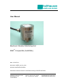
holthausen
elektronik GmbH
User Manual
Electronic Vibration Monitoring Unit
ESW®-Compact/Ex (hol600/Ex)
date: 14.04.2014
document: hol600_ex_hb_e.doc
technical modification possible
holthausen elektronik GmbH is certified according to DIN EN ISO 9001.
holthausen elektronik GmbH
Wevelinghoven 38
41334 Nettetal
Phone: +49 (0) 21 53 - 40 08
Fax: +49 (0) 21 53 - 89 99 4
[email protected]
www.holthausen-elektronik.de
Electronic Vibration monitoring Unit
ESW®-Compact/Ex (hol600/Ex)
holthausen
elektronik GmbH
Table of Contents
1. Generally basical safety-indications ..................... page 4
2. Packing and the transport .................................... page 4
3. Application............................................................ page 5
4. Measurement principle ......................................... page 5
5. Requirement for operation in Ex-Zone ................. page 6
6. Grounding concept ............................................... page 7
7. Mounting of the vibration control unit ................... page 8
8. Opening and closing of the vibration control unit.. page 9
9. Maintenance......................................................... page 9
10. Display- and operation- elements......................... page 10
11. Measurement range switching ............................. page 11
12. Analog output ....................................................... page 11
13. Analog output settings .......................................... page 12
14. Adjustment of the limiting values .......................... page 12
15. Example to adjust the limit value .......................... page 13
16. Self test ................................................................ page 14
17. Housing size......................................................... page 15
18. Cable connection draft ......................................... page 16
19. Type registration .................................................. page 17
Declaration of Conformity ..................................... appendix
Technical Data ..................................................... appendix
2
Electronic Vibration monitoring Unit
ESW®-Compact/Ex (hol600/Ex)
holthausen
elektronik GmbH
Important information
These operation instructions are to be read through completely and carefully heeded
before starting the device. Failure to heed or adhere can result in claims on
manufacturer’s liability becoming null and void for damages ensuing there from.
Manual action of any manner on the device – with the exception of proper procedures
and those described in these operation instructions – lead to forfeit of guarantee and
exclusion from liability.
The device is solely intended for the usage as described below. It is particularly not
intended for the direct or indirect protection of persons.
holthausen elektronik GmbH assumes no liability whatsoever as regards suitability for
some specific purpose.
If any question should remain open, please never hesitate to contact us.
holthausen elektronik GmbH
Wevelinghoven 38, 41334 Nettetal
Phone: +49 (0) 21 53 - 40 08
Fax: +49 (0) 21 53 - 8 99 94
Mail: [email protected]
3
Electronic Vibration monitoring Unit
ESW®-Compact/Ex (hol600/Ex)
holthausen
elektronik GmbH
1. Generally basical safety-indications
Don’t use this device as the only invigilator, if a malfunctioning of ESW ®-Compact/Ex
could lead to damages on goods or Persons.
To obtain the desired result be sure, that the device with its technical data fits to the
bulk of the object you want to supervise.
The sensor is sensitive to shock. A downfall out lower height to a hard substratum can
destroy the sensor.
The assembling place and the execution of the assembling of the sensor determine
decisively the quality of the sensor signal. The assembling may only happen through
qualified and instructed persons.
The electrical hook up is to be done by instructed persons. A mistake by the connection
can entail to faulty functions, outfall or ruination of the sensor and electronics.
The ESW ® should not be used on machines with a very energetic high-frequency solidborne. Through resonance apparitions in the sensor, the device can indicate a much
too great or too small value.
Powerful noise sources for instance inverters, in direct closeness of the sensor,
electronics or cabling, can result in faulty behaving of the apparatus.
Potential differences and balance currents in the mass guidance can result in faulty
behaving too.
The connection cable is resistant against many but not every type of chemicals.
Through a damaged cable chemicals could get inside the unit and destroy the
electronic. Then the unit would loose their function.
Therefore the conditions from the mounting surrounding must be checked. Then the
cover material from the cable have to be proofed if it resists these requirements. You
can get an overview from the chemical resistance of the cover material from us.
2. Packing and the transport
Note:
• The sensor is sensitive to shock. A downfall out lower height to an hard
substratum can destroy the sensor.
• Avoid to kink or tie a knot in the cable.
• Keep the electronic in a dry place.
• In case of a downfall or heckling or squeezing, could the casing or the
operation elements or the board get defects.
With adequate warning-labels and through a qualified packaging and storage, you can
protect the sensor and electronics at carriage against influences from outside.
4
Electronic Vibration monitoring Unit
ESW®-Compact/Ex (hol600/Ex)
holthausen
elektronik GmbH
3. Application
The ESW ®-Compact/Ex unit will be installed on machines like ventilators, blasts,
separators or decanters in order to protect these machines in the application against
inadmissible mechanical vibration. The unit monitor continuously the intensity of
vibration and warn reliably during exceeding of, inside the unit, adjusted limit values.
4. Measurement principle
The mechanical vibrations are measured with a piezoelectric acceleration transducer.
The electronic circuit transforms the acceleration signal into a velocity signal (mm/s),
which is evaluated. The measured range is adjusted by DIP-switches inside the unit.
The measured value is compared with two adjustable limiting values G1 and G2, which
could be adjusted in range of 10% to 100% with two potentiometers inside the unit. At
the analog output the limit values of G1 and G2 can be adjusted when setting of the
DIP-switches corresponds to the prove position. If the measured values G2 exceed the
critical limit, alarm relay K2 will be activated after e.g. 5 seconds delay time. If limit
value G1 is exceeded for more than e.g. 10 seconds, alarm relay K1 will be activated. If
the measured value falls below the limit value, the alarm will be cancelled *).
At the “analog output” the measurement value is proportional to the fitted measurement
range available, by voting 0 to 20mA or 4 to 20mA.
The unit includes a self-test feature witch allow to test all electronic components inside
the unit. Further more it is possible for testing purpose to supply a test signal in to the
measurement electronic.
*) Additional supply with alarm memory. After the activation of the alarm relay K1 (or on
customer request K2) the unit will remain in the alarm status until an external and
manually reset will be activated. This feature is used in such cases, where the vibration
control unit is mounted on unreviewable and difficult accessible places. Through this
advanced memory function every alarm is registered. Because of variable mounting of
one or more parallel connected reset buttons, it is possible to reset the alarm memory
from any place or location.
The reset occurs by connection of the external reset contact (violet wire) to ground.
Attention: Pay attention on requirement by entrance in Ex-Zone
5
Electronic Vibration monitoring Unit
ESW®-Compact/Ex (hol600/Ex)
holthausen
elektronik GmbH
5. Requirement for use of units in Ex-Zone 1 and Zone 21
Potential compensation
The housing of the measurement unit must be connected through the attachment with
the potential compensation of the monitored machine.
The user is responsible that the potential compensation follows the relevant VDEregulations and that the installation is made by a qualified employee.
Wire insertion and connection cable
Wire insertion and connection have to resist a minimum temperature of 90°C.
Connection cable
Attention:
It is not allowed to transport the unit hanging on the connection cable.
The cable insertion is not protected against mechanical tension. The connection cable
must be fastened near the cable insertion in a radius of app. 20cm. The cable should
not be bend and damaged.
General
The installer and user is responsible to follow the Ex-rules, relevant in his application.
6
holthausen
Electronic Vibration monitoring Unit
ESW®-Compact/Ex (hol600/Ex)
elektronik GmbH
6. Grounding concept
main control box
with power supply
optional
connection box
vibration
control unit
shield
shield
+Ub
-Ub
signal ground
signal ground
vibration control unit ground
local
vibration control unit ground
main control
box ground
connection box ground
local
connection box ground
local
main control box ground
If an isolated installation is not specially requested, usually through the attachment with
screws each case is connected to the local machine ground.
Inside the ESW ®-Compact/Ex, dependent on customer request the cable shield and /
or the signal ground to the case potential could be connected by the factory.
Connection to the local ground
The Standard delivery condition for ESW ®-Compact/Ex is that, shielding of the
connection cable is not connected to the case of the unit.
Connection is not implemented to the local ground
Inside the optional plug box, the cable shielding, the box ground and the signal ground
could be connected by choice and dependent on local circumstances and
requirements.
In big facilities with considerable energy consumption and distances between the
machines could such big potential difference be build up, that substantial balancing
current on the ground network will occur. Dependent on intensity of such currents is
arising of interference’s or damaging of the unit the result!
Potential differences could also arise on machines, with small distances not clear
crossing of ground potential for example painted color or movable parts like suspension
mounting.
Energetic high frequency interference energy could be added to the measurement
signal-wire by inductivity or trough capacity that could change the real existing
measurement value! In this way, for example parallel going elements could act as
coupling-capacitor and winded up grounding cable could act like a cut off choke.
Memorize: Ground is not equal everywhere!
Check the situation
Plan the grounding concept
7
Select the facility / realization
holthausen
Electronic Vibration monitoring Unit
ESW®-Compact/Ex (hol600/Ex)
elektronik GmbH
7. Mounting of the vibration control unit
- Whole mounting-, connecting- and adjustment-work should be done from
qualified personal only!
- Protect the ESW®-Compact/Ex definitely against drop, stroke and other
mechanical shock!
- The case of the unit must be connected over the attachment or the ground-onearth-Terminal with the potential compensation of the monitored machine. The
connection must be extremely low resistive as well as for long time stable.
Doing this, take urgent notice to the related VDE-regulations.
ESW-Compact Ex
Surface
max. top hole
11,0
A
18,0
Screw locked M10x25
with LOCTITE protection
0,03 A
M10
ø 80,0
The ESW ®-Compact/Ex will be mounted via one threaded pin AM10*25 per DIN 913 on
the machine to be monitored.
Important
1. Measuring axis has to be coinciding with vibration excitation axis (see case drawing
page 15).
2. Take note of the label with instruction notes.
3. The surface has to be plain, clean and free of paint and rust.
4. The tap hole has to be perpendicular to the surface and free of metal-cuttings or
other foreign material. Further more the tap hole and the screw have to be free of
paint, rust, grease or other isolating components.
5. The grub screw has to be locked with liquid thread protection against unintended
loosening.
6. The unit has to be fixed, tight on the surface.
7. The advises to „connection cable“ (page 6), as well as „Opening and closing of the
vibration control unit “ (page 9) are absolutely to note.
8
holthausen
Electronic Vibration monitoring Unit
ESW®-Compact/Ex (hol600/Ex)
elektronik GmbH
8. Opening and closing of the vibration control unit
The user must switch off the power supply, before opening the measurement unit. To
open the unit the user needs a 1,5mm type of wrench “inbus - key“ and a forehead key
with two-bore nut, with size of 4mm. The case cover is ensured with a M3 screw.
These must be loosened before opening of the case cover, with an “inbus - key”.
After adjustment of the unit, please control the position of the DIP-switches.
Before closing the unit the O-Ring must be examine. You have to insert a new O-Ring
(62 x 2mm, Viton – original spare part) if the old one is brittle, deformed, damaged or
already a few month in use.
Please pay attention that the thread and the interior room is oil- and dirt- free. Cleaning
around and inside the unit should be done only with clean and dry cloth. The closing
and the sealing of the unit is done after app. seven pitches of cover-nut thread, and
ensured via the M3 screw.
“Loosen of the screw on the case bottom and opening of the bottom nut is not
permitted.“
Advises for dismantling
Before dismantling the measurement unit, the power supply must be switched off. The
connection cable has to be loosened from the supporting surface to avoid damaging of
the cable. The vibration control unit should be set free via a 22mm wrench key.
9. Maintenance
The ESW ®-Compact/Ex is maintenance free.
The fuse F1 is soldered fixed and should exclusively be replaced by qualified personal.
For replacement is a SMD-fuse, type OMF (63V,1A) required.
Tools for case cover opening:
1.5mm type of wrench (Inbus-key)
Adjustable forehead key for two bore nut size 4mm
Factory: H. Sartorius Nachf. GmbH & Co
phone +49 (0) 21 02 / 44 00 - 0
fax
+49 (0) 21 02 / 44 00 - 24
9
holthausen
Electronic Vibration monitoring Unit
ESW®-Compact/Ex (hol600/Ex)
elektronik GmbH
10. Operating and setting instructions
The display and operating elements will be accessible after unscrewing the cover of the
ESW ® Compact/Ex.
Display elements
LD2
LD1
LD3
yellow LED
green LED
red LED
R
ESW -Compact
Self test “active“
Operating voltage “on “
Limit value G1 exceeded for
more than the rise time, K1
has switched
SN:
LD2
LD1
LD3
on
S1 S2 S3 S4 S5 S6 S7 S8
off
P1
Operating elements
P1
P2
Potentiometer for setting limiting value G1
Potentiometer for setting limiting value G2
10 to 100%
10 to 100%
S1
S2
S3
S4
Range 0 to 10mm/s
Range 0 to 20mm/s
Range 0 to 50mm/s
Analog output
0 to 20mA
4 to 20mA
Analog output corresponds to measured value
Analog output corresponds to limiting value G1
Analog output corresponds to limiting value G2
Self test activated
ON/OFF
ON/OFF
ON/OFF
ON
OFF
ON/OFF
ON/OFF
ON/OFF
ON/OFF
S5
S6
S7
S8
10
P2
holthausen
Electronic Vibration monitoring Unit
ESW®-Compact/Ex (hol600/Ex)
elektronik GmbH
Setting instructions
R
ESW -Compact
After applying the voltage supply
the green LED LD1 must light up. The
yellow and the red LED should remain
dark. The relays are switching in there
normal position.
SN:
LD2
LD1
LD3
on
S1 S2 S3 S4 S5 S6 S7 S8
off
P2
P1
11. Measurement range switching
The unit has three measurement ranges, which can be selected by the switches S1, S2
and S3. For a proper operation of the unit, only one switch has to be in position “ON”,
the both other switches should remain in position “OFF“.
Range
Switch Position
10mm/s
20mm/s
50mm/s
S1
ON
OFF
OFF
S2
OFF
ON
OFF
S3
OFF
OFF
ON
12. Analog output
As the output value will be submitted constant current, by voting 0 to 20mA or
4 to 20mA. The selection occurs by switching over of switch S4.
An output current of 20mA meets the 100%-value of the selected measurement range.
In the setting of 0 to 20mA is the valid relation 0.2mA per %, in the setting of
4 to 20mA is the valid relation 4mA + (0.16mA per %).
Output range
Switch position
0 to 20mA
4 to 20mA
S4
ON
OFF
11
holthausen
Electronic Vibration monitoring Unit
ESW®-Compact/Ex (hol600/Ex)
elektronik GmbH
13. Analog output settings
The 0 to 20mA output can be used for displaying of several values on the analog
output. With the standard setting the output current corresponds to the measured
signal.
For example, an analog current value of 20mA corresponds to a measured vibration
velocity that has reached 100% of the measuring range set.
Important: By switching over the Dipswitches, the analog output can be used for
setting or reading of the limit values G1 and G2.
The limit value adjustment means a current of 20mA, so that the switch level close to
100% of the adjusted measurement range.
Output Variable
Switch Position
Vibration velocity
Limiting value G1
Limiting value G2
S5
ON
OFF
OFF
S6
OFF
ON
OFF
R
ESW -Compact
SN:
S7
OFF
OFF
ON
LD2
LD1
LD3
on
S1 S2 S3 S4 S5 S6 S7 S8
off
P2
P1
14. Adjustment of the limiting values
If the measuring signal exceeds certain limiting values, the ESW ®-Compact/Ex shall
react by switching potential-free relay contacts. These limit values can be set inside the
unit by potentiometers. The limit values can be set between 10% and 100% of the
selected measuring range.
The limit value G1 will be adjusted with potentiometer P1. Exceeded the value of G1 for
longer as 10s, then K1 is switched. The limit value G2 will be adjusted with
potentiometer P2. If limit of G2 will be longer than 5s exceeded, then K2 is switched.
Rest the measured value just from time to time over the limit value, so counts the
activation delay time after each overstepping of the limit value once more.
When the analog output of the limiting value setting is switched over, the output current
related to 20mA will correspond to the setting of the limiting value related to 100% of
the measuring range. If, e.g. G1 has to be set to 15mm/s = 30% in the measuring
range of 50mm/s, the output range will be first set to 0 to 20mA via S4 and the output
variable to limit value G1 via S5=OFF, S6=ON and S7=OFF. After that, a current
output of 6mA (= 30% of 20mA) has to be adjusted by potentiometer P1.
A current of 8.8mA (= 4mA + 30% of 16mA) should be set in the output range 4 to
20mA. The difference between 4 and 20 is 16 30% of 16mA + 4mA = 8.8mA
After setting the limiting values, please pay attention that S5 is set to position “ON“ and
S6, S7 to position “OFF“ to activate the function of the analog output as a measuring
output.
12
holthausen
Electronic Vibration monitoring Unit
ESW®-Compact/Ex (hol600/Ex)
elektronik GmbH
15. Example to adjust the limit value
Example 1: Analog output 0 to 20mA (mean 0.2mA per %)
Adjust the limit value G1 to 22.5%, and the limit value G2 to 35%:
Measured range 20mm/s
S1
S2
S3
OFF
ON
OFF
Analog output 0 to 20mA
S4
ON
Balancing of the limit value G1 to 22.5%
S5
OFF
S6
ON
S7
OFF
Set the output current to 4,5mA via P1 (22.5% of 20mA is 4.5mA)
Balancing of the limit value G2 to 35%
S5
OFF
S6
OFF
S7
ON
Set the output current to 7mA via P2 (35% of 20mA is 7mA)
Measuring variable “vibration velocity“
S5
S6
S7
ON
OFF
OFF
Self test off
S8
OFF
Example 2: Analog output 4 to 20mA (mean 0.16mA per %)
Adjust the limit value G1 to 45%, and the limit value G2 to 60%:
Measured range 20mm/s
S1
S2
S3
OFF
ON
OFF
Analog output 4 to 20mA
S4
OFF
Balancing of the limit value G1 to 45%
S5
OFF
S6
ON
S7
OFF
Set the output current to 11.2mA via P1 (45% of 16mA is 7.2mA + 4mA)
Balancing of the limit value G2 to 60%
S5
OFF
S6
OFF
S7
ON
Set the output current to 13.6mA via P2 (60% of 16mA is 9.6mA + 4mA)
Measuring variable “vibration velocity“
S5
S6
S7
ON
OFF
OFF
Self test off
S8
OFF
13
holthausen
Electronic Vibration monitoring Unit
ESW®-Compact/Ex (hol600/Ex)
elektronik GmbH
16. Self test
A self-test circuit in the unit is integrated to check the ESW ®-Compact/Ex for correct
operation. The self-test function could be activated by switches inside the unit and is
optically displayed by a yellow LED. After expiration of fixed delay time has K1 and K2
to be switched, and the red LED “Alarm“ must light up. The analog output must give out
a current of over 22mA. During the self-test function is the whole electronic
incorporated, so that it’s possible to obtain a definite information about the function of
the unit.
R
ESW -Compact
Function
Switch position
Self test on
Self test off
S8
ON
OFF
SN:
LD2
LD1
LD3
on
S1 S2 S3 S4 S5 S6 S7 S8
off
P2
P1
Upon execution of the self-test function, it’s absolutely necessary to return the switch S8
to the position OFF in order to ensure the proper function of the ESW ®-Compact/Ex. The
yellow LED must darken and current has to return to his normal value.
In case the yellow LED is lighting and a higher output current is flowing, without of
activation of S8, than the electronic recognize one sensor defect and starts alarm,
because the electronic is continuously monitoring the sensor.
14
holthausen
Electronic Vibration monitoring Unit
ESW®-Compact/Ex (hol600/Ex)
elektronik GmbH
17. Housing size (in mm), with optional ground on earth terminal
77
23
69
102
measuring axis
~23
ground on earth terminal 4mm²
max. 10mm top hole
M10
SW22
50
ø4.2 x 5
Authorization N.B.:
BVS 08 ATEX E 089 X
Material:
high grade steel V4A
Weight:
2350g
Protection:
IP 68
Cable insertion:
CAPRI Type ADE 1F-4F, IP68, with Neopren-airtight ring
15
Electronic Vibration monitoring Unit
ESW®-Compact/Ex (hol600/Ex)
holthausen
elektronik GmbH
18. Cable connection draft
Version without external reset
ESW®-Compact/Ex
+24V supply volt.
ground
red
: +24V supply voltage
blue : ground
grey : analog output
yellow : closer contact K1
green : middle contact K1
white : closer contact K2
brown : middle contact K2
violet : not connected
black : not connected
orange : not connected
analog output
closer contact K1
middle contact K1
opener contact K1
closer contact K2
middle contact K2
opener contact K2
shield : see page 7 ´Grounding Concept´
Regulary here ends the cable shield in the housing and is isolated to the case.
The outlined contacts of the alarm-relays are in position: without supply voltage.
Under normal working conditions are the closer- and middle-contacts connented.
On request is the connection of the remaining contacts in a other way with
an other cable also possible.
Version include external reset
ESW®-Compact/Ex
+24V supply volt.
ground
red
blue
grey
yellow
green
white
brown
violet
: +24V supply voltage
: ground
: analog output
: closer contact K1
: middle contact K1
: closer contact K2
: middle contact K2
: external reset (activ by
connection to ground)
black : not connected
orange : not connected
shield : see page 7 ´Grounding Concept´
analog output
closer contact K1
middle contact K1
opener contact K1
closer contact K2
middle contact K2
opener contact K2
external reset
Regulary here ends the cable shield in the housing and is isolated to the case.
The outlined contacts of the alarm-relays are in position: without supply voltage.
Under normal working conditions are the closer- and middle-contacts connected.
On request is the connection of the remaining contacts in a other way with
an other cable also possible.
16
Electronic Vibration monitoring Unit
ESW®-Compact/Ex (hol600/Ex)
holthausen
elektronik GmbH
19. Type registration
The unit with the type registration HOL 6xx/Ex is certified by the ATEX guideline 94/9
EC for the use in gas-air-mixture under atmospheric conditions or burnable dust.
Labeling / Registration
Company address
holthausen elektronik GmbH
Wevelinghoven 38
D- 41334 Nettetal
Type
Environment temperature
Gas registration
Dust registration
HOL 6 . . /Ex
-20°C ≤ Tamb ≤ +65°C
II 2G Ex d IIC T6
II 2D Ex tD A21 IP68 T80°C
Serialnumber
XX = calendar week/ XX = Year/ XXXX = continuous number
Approvalnumber
BVS 08 ATEX E 089 X
CE 0035
®
ESW is a registered trademark of holthausen elektronik GmbH, Wevelinghoven 38, 41334 Nettetal
17