1
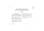
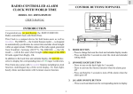
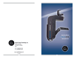
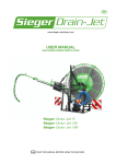
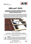
10KW Grid-tie Wind Generator
USER’S MANUAL
Contents
1. Main Parts ------------------------------------------------------------------------------------------------------------ 3
2. Safety Guideline ---------------------------------------------------------------------------------------------------- 3
3. Foundation ----------------------------------------------------------------------------------------------------------- 4
4. Preparation ------------------------------------------------------------------------------------------------------------4
5. Installation ------------------------------------------------------------------------------------------------------------ 5
6. Electrical Connection---------------------------------------------------------------------------------------------- 9
7. Specifications -------------------------------------------------------------------------------------------------------- 9
8. Maintenance ----------------------------------------------------------------------------------------------------------11
9. Trouble Shooting ----------------------------------------------------------------------------------------------------12
Appendix A --------------------------------------------------------------------------------------------------------------- 14
Appendix B --------------------------------------------------------------------------------------------------------------- 15
2
1. Main Parts
1. Tail vane
3.
Wind Rotor
1. Nacelle Arm
3. Nacelle Shaft
5.Wicket
2. Nacelle
4. Mast assembly (Tower)
2. Hydraulic Brake Device
4. Winch
2. SAFETY GUIDLINE
This chapter indicates some rules you should follow while using.
--The generator shall be stopped when the wind speed is more than 25m/s.
--The tower should not be installed near unprotected power lines. All electric wires and cables should
be considered dangerous.
--Do not let the generator run free of load when wind speed exceeds 8m/s.
--Do not approach wind generator when the air vane is rotating
--If any abnormal noises or serious oscillation are detected, please stop the generator and check.
--The AC output cables shall be laid separately, do not lay out with other cables.
--In the process of assembling wind power system with batteries, you must connect the batteries then
connect the generator output cables; in disassembly, you must disconnect the generator output cables
3
then disconnect the batteries.
--The "ON/OFF" switch on electrical cabinet or separate
Shorting switch shall be in "ON" position. The function of this switch is to pause the generator to defend
damaging gale or typhoon. If the wind speed is under 5m/s, and the wind vane is turning slowly, you
can switch "ON", but do not switch when wind speed is high.
--The batteries shall be installed in some place away from heat or fire. Keep good venting, so the gas
created in charging can be dispersed.
--The tail vane is equipped with gale protecting lock. If the gale is gone, reset it manually. First switch
the ON/OFF switch to OFF, then climb to the tower top and unlock the tail vane. Pay attention to the tail
vane after unlock to avoid injury.
3. FOUNDATION
3.1 Dig rectangular pit on site. Please note the foundation types and installation approaches are site
specific and the foundations must be designed for the load conditions expected at the site in question.
For detailed dimension, length, width and depth of the pit, please follow civil engineer’s suggestions.
Take silty clay soil (bearing capacity not lower than 120kpa) for example, for mast assembly height is
15m, the pit dimension shall be 3mX3mX2m, while for mast assembly height is 30m, and the pit
dimension shall be 4mX4mX3m.
3.2 Place steel bars & anchor bolts into the pit as per appendix A, remember to remain a cable trench.
Adjust the anchor bolts template in level.
Prepare concrete as per Appendix A specified, place concrete inside, meanwhile oscillate to make it
firm.
3.3 After concrete is placed, keep the concrete surface moist for curing for 200 hours. The visible parts
of anchor bolts shall be coated with grease or fastened with plastic film to avoid corrosion.
4. PREPARATION
4.1 To install a wind generator requires specialized skills, devices and experience. Information supplied
by us and our suppliers, for the purposes of installing, operating and maintaining all equipment,
assumes that personnel have the skills, experience and devices needed. No one shall attempt to climb
the tower and operate or maintain wind turbines without the necessary skills, experience, tools and
safety equipment.
4.2 It is essential for the reader to be familiar with the manual before preparing the site, installing
equipment, operating the system or servicing any equipment.
4.3 The site shall be prepared, maintained, operated and managed to allow work to be performed
safely and efficiently. Special care shall be given to installing, operating and maintaining the generator
system under unusual conditions such as lightning, high winds or icing (where applicable). If you have
any operation or service related questions, please contact us.
4.4 Prepare batteries, inject acid and charge if the attached instruction specified.
4
4.5 Open the crates and check the packing list to confirm that all items have been received. The items
shall be inspected for damage.
4.6 Choosing a good place with good conditions. To reduce wire loss, reduce the distance from the
wind generator to the batteries (or electrical cabinet). The wire shall be bigger for long distance while
the distance is within 100 meters.
5. INSTALLATION]
Please install wind generator system when wind scale is less than Force 2 (ie. 4 – 7 mph)
5.1 Tower Assembly
Place lower mast and middle mast on level ground, clean the flanges; make the masts in one line, put
silicon glue on contact surfaces for better sealing. Insert bolts and tighten nuts to couple the upper mast
flange and middle mast flange.
Note: Please tighten all nuts and bolts with socket wrenches and with proper torque, do not damage
their coating to avoid corrosion. It is critical that bolts be equally tightened in a sequential pattern
diametrically opposed to each other)
5.2 Nacelle Hub Assembly
5.2.1 Make the mast assembly on ground level; keep the side with holes (for access ladder) up. Put the
button end near the foundation, and then lift the top end 0.3m above the ground
5.2.2 Place the generator and nacelle close to mast assembly top flange; keep the nacelle shaft near
mast assembly top end flange.
5.2.3 Pull the steel wire end from the nacelle shaft, connect and extend steel wire as long as to access
the winch. Let the steel wire through the mast assembly and out from mast bottom wicket, tie the wire
end on wicket temporarily
5.2.4 Open mast assembly top cover; connect three AC output cables and let them through the mast
assembly; fix them on terminal bolts inside mast assembly bottom.
5.2.5 Connect cables from the foundation trench; let them through the wicket to the terminals. Connect
5
the cable ends on terminals; fix the cables on inner side of mast to avoid the terminals endure too much
weight.
5.2.6 Let the nacelle right cover side up, lift the generator with the nacelle to couple the nacelle shaft
flange and the mast assembly top flange. Avoid the steel wire and cables being damaged in flange
coupling. Each bolt shall with a spring washer; the bolts shall be tightened with proper torque. Then set
the nacelle stable.
5.3 Tail Vane Installation
5.3.1 Assembly straight tail beam, bent tail beam, rain cover, pulley, pulley shroud, tail rod, tail grid and
tail plate together.
•
Put the tubular pin Φ50X190 through pulley and pulley shroud, install them on the tail rod. Note: for
pulley shroud the side with plate shall be on top side.
•
Put the straight beam upside and the bent beam downside, align proper position and insert bolt
M27X410 with washer. Put nut, but do not tighten.
•
Use 4 M10X25 bolts to fix rain cover on straight beam through 4 M10 screw holes.
•
Use stainless steel bolts (M10X70), plate washers, spring washer and self-lock nuts to fix tail skid
grid on tail plate.
•
Fix the vane plate with stainless steel bolts M10X35. The big plate washers and spring washers
shall be used on right side of tail rod plate and tail grid. Use self-tight nut and tighten them with proper
torque.
•
Put the tail vane right side up, lift the vane assembly and move it approaching the nacelle. Let the
6
tail beams astride on nacelle, with 2 Φ50holes near two spherical bearings on nacelle tail. Insert tail
pin from tail beam side; tighten the M16X30 bolts with Φ3 holes. Fix these two bolts with stainless
steel wire, and then tighten 4 M8 Allen bolts on upper and lower spherical bearings inner ring. Lock
the tail pin upper end with 2 M45X1.5 round nuts and lock washer. Finally tighten 2 M27X410 bolts
with proper torque.
5.3.2 Mount brake arm on tail pin, tighten 2 M12X35 bolts.
5.3.3 Turn the nacelle, let the rotor shaft up. Fix the nacelle with frame and put the tail vane on wood
plate.
5.4 Nacelle Arm Installation
5.4.1 Mount the nacelle arm assembly on nacelle and fix 6 M16X30 bolts with spring washers.
5.4.2 Open the nacelle upper cover, untie the steel wire. Let the steel wire end passing through pulley 1,
pulley 2 and pulley 3, fasten the end to the flexible ring on nacelle arm. The steel wire bush shall be
tightened with 2 wire clamps.
5.4.3 Close the upper cover, tighten 2 M10X25 bolts.
5.5 Blades Installation
5.5.1 Mount rotor hub on rotor shaft, put washer and lock washer and then tighten the nuts with proper
torque. For the convenience of inspection in future, mark the nuts with colored paint.
5.5.2 Mount the blades and nose cone frame on rotor hub with 130~150Nm torque. The blots to fix
7
blade shall be with special plate washer and special spring washer. Paste waterproof glue on blade root
gaps and bolts & washers in inner side of hub flange.
5.5.3 Mount nose cone. Use 6 M10X25 bolts (with spring washers and big size-plate washers)
To avoid rotor rotating during assembly process, please short-circuit 3 phases output cables
5.6 Working Ladder & Platform Installation
5.6.1 The working ladder consists of several segments. For each segment the standard length is 3m.
The sequence shall be from mast assembly top to bottom. If the mast assembly is in 15m, the ladder
includes 3 segments in 3m, and 1 segment in 2.12m. The segment in standard length shall be fixed
with 3 M16X40 bolts. If the mast assembly height is not in 15m, the remainder length will be the bottom
section length. Use 2~4 M16X40 bolts to fix it.
5.6.2 Mount 5 brackets on upper mast. Each bracket shall be fixed by 4 M16X40 bolts. To install
platform smoothly, it’s better not to tighten the 4 M16X40 bolts before all bolts are inserted in position.
5.7 Wind Generator System Erection
All lifting devices should be inspected for integrity, suitability for purpose and correct attachment before
lifting.
A designated person should be clearly identified as the lift coordinator. The lift coordinator should direct
all equipment and personnel during the lift. Supplementary radio contact is strongly recommended.
5.7.1 Fasten the position pins in anchor bolts.
5.7.2 Tie the lifting belt on mast assembly top flange; lift the wind generator system slowly
The nacelle and the tail vane shall not be used for lifting! Avoid cables at mast bottom end being
8
damaged.
5.7.3 Use Allen key to take position pins out and put nuts on. Adjust 48 nuts up and beneath the anchor
bolts template let the mast assembly upright against level. The verticality tolerance shall be
0.002Xmast assembly height. Keep the mast assembly vertical and tighten the nuts. It is critical that
bolts be equally tightened in a sequential pattern diametrically opposed to each other. The proper
torque is 380~400Nm.。
5.7.4 If a crane is not available, the user can set up two scaffolds which are 2~3m higher than the mast
assembly and let them 4m aside. Fix one H steel bar, with two end on top of two scaffolds. Install
working platform and prepare hoist chain, pulley and chain blocks. First assemble, erect and fix mast
assembly on foundation, then install the nacelle, tail vane and rotor.
5.8 Brake and Yawing Device Installation
5.8.1 Install winch and connect wire
5.8.2 Commission hydraulic brake device
5.8.3 Add brake oil and press driving cylinder, then loose drain screw. Repeat this process to drain out
air in driving and driven cylinders then tighten the drain screw. It should be like this: when you push the
brake handle, the handle travel little distance you can feel the hydraulic resistance. Turn the wind rotor
and check the brake torque. It shall be more than 350Nm. But when the brake is released, the rotor
shall run when wind speed exceed 4m/s.
6. ELECTRICAL CONNECTION
6.1 If batteries are used, please:
--- Join batteries in series. The lead wire and connecting wire shall be with rubber covered cooper wire.
The conducting section shall be more than 16 m2 Put red mark on positive pole while put black mark
9
on negative pole. All joints shall be connected with clamps and with good conduction. To avoid
corrosion, please coat protective grease on leads and joints.
--- Connecting generator output cables (3 phases) to AC terminals on electrical cabinet.
--- For different users, the electrical cabinet is equipped with AC and DC output terminals. Choose
correct terminals to avoid hazards.
Please take wind conditions, load and batteries capacity into account, do not over discharge or charge
batteries for this may short the service life.
6.2 If a grid-connected converter is used, please connect wire as appendix B. The wind generator
output DC voltage shall be in inverter input voltage range.
---The controllers shall be equipped with bleeder load that is three times larger than generator rated
output power
---Over speed and over load stop control system or devices shall be installed.
7. SPECIFICATIONS
Rotor Diameter(m)
7
Blades Material/Quantity
G.R.P./3
Rated Power/Max. Power(KW)
10/17
Rated Wind Speed(m/s)
12
Start Wind Speed(m/s)
3
Normal Working Speed(m/s)
3-25
Survival Wind Speed(m/s)
40
Rated Revolution (r/min)
200
Voltage (V)
DC500V
Generator Type
Permanent Magnetic, 3 phases AC
Charging Method
3-Phase full wave rectify, constant voltage
AC380V
charging
Governing
Yawing control
Shutdown
Manual Hydraulic Brake, Electrical Driving Yawing
Tower Height (m)/ Weight(kg)
15/2800; 25/6000
Machine Above Tower Weight
1200
Service Life
>15 year
10
8. MAINTENANCE
8.1 Fasteners inspection
8.1.1After one month’s running
After one month’s running, all fasteners shall be checked, if any fasteners are loose, tighten with proper
torque. Pay extra attention to nuts on anchor bolts, bolts in the joints of mast segments, bolts in the joint
of nacelle shaft and upper mast, hub mounting bolts, blades mounting bolts, nose cone bolts, bolts to
mounting generator on nacelle, round nuts on nacelle bolts and upper/lower nuts & bolts on tail vane
pin.
8.1.2 Undergone initial strong wind
Inspection work mentioned in 7.1 shall be done if the generator system has undergone strong wind
(25m/s ) for the fist time.
8.1.3Annual Inspection
Annual inspection is necessary. If following parts are detected to be loose, they shall be replaced with
new parts and be tightened with proper torque: nuts on anchor bolts, bolts in the joints of mast
segments, bolts in the joint of nacelle shaft and upper mast, hub mounting bolts, blades mounting bolts,
nose cone bolts, bolts to mounting generator on nacelle, round nuts on nacelle bolts and upper/lower
nuts & bolts on tail vane pin.
8.2. Welding Seams inspection
8.2.1 After 1000 hours’ running, inspect seams in mast assembly (pay extra attention to mast root,
coupling flange and mast top flange), hub and tail beams to detect if any cracks or defects.
8.2.2 After 5000 hours’ running, inspect all welding seams to detect if any cracks or defects
8.2.3 Inspection work mentioned in 7.2.1 shall be done if the generator system undergone strong wind.
8.3 Yawing Device Inspection
8.3.1 Frequently check if the wind generator yawing device runs smoothly or not. Use manual handle or
electrical winch to turn the tail vane (45°~60°) to check if the system is stiff. Release the winch and the
tail vane shall back to position.
8.3.2 After 1000 hours’ running the user shall check the pulley system: to check if the pulley run freely
or not, add lubricating oil if necessary, to check if the steel wire joints are firm or not, to check if the steel
wire is damaged or seriously worn. If the steel wire is damaged, please replace, if any pulley is stiff,
please dismantle is and repair.
8.4 Oscillation Detection
The wind generator shall not oscillate seriously in operation, otherwise please shutdown and check:
8.4.1 Check the rotor
--if any blades mounting bolts are loose or missing
--if any visible defects and cracks in blades. Pay extra attention to blade roots and tips
--static balancing shall be G2.5~G6.3 while unbalance shall be 25gm~63gm
--face run-out shall not exceed 30mm
--tip angle difference in 3 blades shall not exceed 0.5°
11
8.4.2 Check the generator. Oscillation can be caused of phase loss. Please check 3 phases output
voltage
8.4.3 Check brake system if there are any distortion, displacement, unequal worn-out, missing parts or
stiff moving
8.5 Generator Output Circuit Inspection
8.5.1 Check 3 output cables if they are firmly fixed in nacelle and cable cover is damaged or not.
8.5.2 Check 3 cable leads if they are firmly fixed with carbon brushes and well contacted.
8.5.3 Check 6 carbon brushes are well contacted with slide ring or not. Check if any overheated
indications. Every 3000 hours, the contact surface shall be cleaned and grinded. Over worn
brushes shall be replaced with new ones. New carbon brushes need run-in before use. The
effective ratio of contact surface between the brushes and slide ring shall exceed 90%.
8.6 Brake System Inspection
8.6.1 Check oil system, from driving cylinder to driven cylinder, if any oil leakage.
8.6.2 After initial 1000 hours’ running, the oil level shall be checked. After this every 3000 hours this
check shall be performed.
8.6.3 After every 3000 hours, check the conditions of brake disc and brake shoes. Check the brake
torque, the brake torque shall be more than 350 Nm.
8.7 Lubrication
8.1 Use grease gun to inject grease into nacelle upper / lower oil holes, tail vane spherical oil holes
(two)
8.2 Add lubricating oil to pulleys and winch after every 3000 hours’ running.
8.3 Clean, maintain and lubricate generator after every 20000 hours’ running. Use high class lithium
base grease.
9. TROUBLE SHOOTING
Complaints
Causes
1.
2.
①
wind rotor not
start in 4m/s
wind
3.
4.
5.
6.
②
Bad wind rotor
orientation
③
Slow wind rotor
bad blade angle
uneven wind rotor even
blades dropped down
start torque too big
generator output short
circuit / too early load
stiff brake system
wind rotor not facing wind
1、 nacelle bearing stiff
2、 tail vane not back position
1、 blade angle too big
2、 generator bearing worn
Solutions
1、 align as per requirement
2、 do static balance
detection
3、 detect generator torque
4、 find short circuit place
5、 find stiff place
6、 check nacelle shaft, align
tightness
1、 align bearing gap or replace
2、 check and solve
1、 align as per requirement
2、 check and replace
12
revolution
④
Serious
Oscillation
3、 output cable short circuit
4、 improper load
5、 brake device not release
1、 blade mounting bolts loose
2、 blades coated with ice
3、 blades missing
4、 output circuit phase loss
5、 nacelle bearing worn or
damaged
6、 tail vane bearing worn or
damaged
7、 stiff brake system
8、 too light load in yawing
9、 over speed running in gale,
without load
1、 fasteners loosing(nose cone,
hub, blades mounting bolts,
etc.)
2、 unbalance output from
generator
⑤
Serious Noise
3、 generator bearing loose or
damaged
4、 nacelle bearing loose or
damaged
5、 brake system to tight
6、 parts in nacelle loose
7、 tail vane bearing loose
8、 tail grid mounting bolts loose
9、 wind rotor over speed
3、 check and solve
4、 align voltage and loading point
5、 check and solve
1、 replace and tighten with proper
torque
2、 remove ice and align balance
3、 repair blades
4、 check and solve
5、 tighten or replace
6、 check and repair
7、 increase proper load
8、 shutdown to check
1、 detect and solve
2、 check and solve
3、 check and replace
4、 align gap and tighten
5、 check and repair
6、 tighten
7、 replace
8、 tighten
9、 shutdown and solve then start
⑥
Wind rotor over
speed even
exceed rated
speed
1、run in free load condition
2、too light load
3、nacelle bearing too tight
4、mast not upright
5、yaw angle not enough
6、Stiff tail vane bearing
1、shutdown and check
2、align load and output relation
3、keep good tightness. Proper
bearing gap is 0.2mm
4、align ;verticality, <100mm on top
5、align to let tail turn 80°
6、check and repair/replace
⑦
Can not
shutdown
1、controlling system faults.
bleeder can not start in time
2、weak bleeder
3、yawing device and brake
system out of work
1、check and solve
2. increase bleeder capacity
3、check and repair, brake torque shall
be more than 350Nm
13
APPENDIX A
14
APPENDIX B
15
16