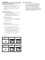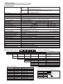
1
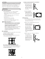
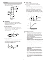
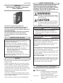
SAFETY PRECAUTIONS CP-SP-1220E Safety precautions are for ensuring safe and correct use of this product, and for preventing injury to the operator and other people or damage to property. You must observe these safety precautions. Also, be sure to read and understand the contents of this user's manual. IP51FVL INTELLPAK Pulse/DC Converter User's Manual WARNING Warnings are indicated when mishandling this product might result in death or serious injury to the user. CAUTION Cautions are indicated when mishandling this product might result in minor injury to the user, or only physical damage to this product. Thank you for purchasing the IP51FVL. This manual contains information for ensuring correct use of the IP51FVL. It also provides necessary information for installation, maintenance, and troubleshooting. This manual should be read by those who design and maintain devices that use the IP51FVL. Be sure to keep this manual nearby for handy reference. WARNING • Before wiring, removing, or mounting the IP51FVL, be sure to turn the power OFF. Otherwise, touching electrically charged parts could cause electric shock. CAUTION RESTRICTIONS ON USE •Use the IP51FVL within the operating ranges given in the specifications for temperature, humidity, voltage, vibration, shock, mounting direction, atmosphere, etc. Failure to do so could cause malfunction. •Do not allow lead clippings, chips or water to enter the case. Doing so could cause fire or faulty operation. •Firmly tighten the terminal screws at the torque listed in the specifications. Insufficient tightening of terminal screws could cause electric shock or fire. •Do not use unused terminals on the IP51FVL as relay terminals. Doing so could cause electric shock, fire, or faulty operation. •Do not block ventilation holes. Doing so could cause fire or faulty operation. •Do not touch electrically charged parts such as the power terminals. Doing so could cause electric shock. •Do not disassemble the IP51FVL. Doing so could cause electric shock or faulty operation. This product has been designed, developed and manufactured for general-purpose application in machinery and equipment. Accordingly, when used in applications outlined below, special care should be taken to implement a fail-safe and/or redundant design concept as well as a periodic maintenance program. • Safety devices for plant worker protection • Start/stop control devices for transportation and material handling machines • Aeronautical/aerospace machines • Control devices for nuclear reactors Never use this product in applications where human safety may be put at risk. NOTICE Be sure that the user receives this manual before the product is used. Copying or duplicating this user’s manual in part or in whole is forbidden. The information and specifications in this manual are subject to change without notice. Conventions Used in This Manual Considerable effort has been made to ensure that this manual is free from inaccuracies and omissions. If you should find an error or omission, please contact Yamatake Corporation. The following conventions are used in this manual: Handling Precautions: Handling Precautions indicate items that the user should pay attention to when handling the IP51FVL. (1), (2), (3): Numbers within parentheses indicate steps in a sequence or parts of an explanation. In no event is Yamatake Corporation liable to anyone for any indirect, special or consequential damages as a result of using this product. 2007 Yamatake Corporation ALL RIGHTS RESERVED 1 ● How to attach the IP51FVL to the DIN rail (1) Attach the socket first With the slider on the base of the socket facing downward, hook the socket onto the DIN rail. Then push in the base of the socket, as shown in the drawing. 1.Outline The IP51FVL is a thin plug-in type pulse/DC converter designed for extremely slow pulses. It receives a slow input pulse signal, calculates the frequency from the cycle with a built-in microprocessor, and generates an analog output signal with a voltage or current proportional to the calculated frequency. 2.Mounting ■ Mounting locations (2) Attach the IP51FVL Push the IP51FVL straight into the socket. The label lettering should be pointing the right way. Be sure to push the unit firmly into the socket. Install the IP51FVL so as to avoid the following: • High and low temperatures and humidity • Direct sunlight, outdoor locations exposed to wind and rain • Splashing liquid such as water, oil, or chemicals • Corrosive or flammable gases • Dust and soot • Mechanical vibration and shock • Strong electric or magnetic fields • Sources of electrical noise, such as high voltage ignition devices or welding machines Handling Precautions: • When installing the IP51FVL in a place subject to mechanical vibration or shock, attach a damping bracket like the QN718A (sold separately). A damping bracket cannot be attached if the IP51FVL is mounted on a DIN rail. • When installing the IP51FVL in place with much dust or metal powder, mount it in a case designed to be dustproof, and take measures to prevent excessive heat. ■ Removing (1) If the damping bracket is attached to the IP51FVL, remove the damping bracket first. Then remove the IP51FVL from the socket. (2) How to remove the IP51FVL from the socket First make sure that the IP51FVL is fully pushed onto the socket. Fully press both upper and lower levers on the IP51FVL and pull it straight off the socket. Pulling it off when the levers are not sufficiently pressed can damage the socket. ■ Installation The IP51FVL plugs into a socket which can be attached directly to a wall or to a DIN rail. ● Lateral installation layout When installing multiple IP51FVL units side by side, use the layout shown below. (3) How to remove the socket from the DIN rail Insert a flat-head screwdriver into the slit of the DIN rail holder, and pull it down. Then lift the socket off the DIN rail in the direction shown by the arrow in the figure right. Unit: mm 80 min. 80 min. Duct etc. 15 2-M4 26 min Duct etc. ● Installation layout with damping bracket When installing the IP51FVL with the damping bracket, use the layout shown below. (The QN718A damping bracket is sold separately.) Unit: mm 4-M3 65 80 min. Duct etc. 38 15 80 min. 2-M4 49 min. Duct etc. 2 ■ Output wiring 3.Wiring Connect the output to terminals 5 and 6. Wire the unit as shown in the figure below. Use M3.5 crimp contacts for wiring. ● Input-output relationship and dropout frequency The IP51FVL frequency-voltage converter calculates the period of an input pulse train and then converts it to DC output proportional to the pulse frequency. For this reason, if there is no input pulse for longer than a prescribed time, the output automatically changes to zero or the minimum voltage. This frequency is called the dropout frequency and is 1% of the input frequency. The output of this converter is refreshed within 1 second of every pulse input. If the input frequency exceeds the rated value, the output is saturated at the rated voltage. Input Output Load 1 2 3 4 5 6 7 8 FG Input 24 Vdc or 100/110/120 Vac 200/220/240 Vac 50/60Hz f1 Output f2 1s V1 f3 V2 Dropout frequency V3 Time ■ Input wiring Connect the input signals indicated on the label to terminal 1 (+) and terminal 2 (-). The signal duty ratio should be between 25% and 75%. 100% Output ● Input type code 11 This input circuit is for a sensor with open collector output or no-voltage contacts. The applied voltage (V) at OFF is 5V, and the current at ON (Is) is approximately 1mA. Dropout frequency Input frequency Handling Precautions: • Be sure to use insulated crimp contacts for terminal connections. When installing the IP51FVL in a place with heavy mechanical vibration or shock, use ring terminals so that they do not come loose. • Make sure that nearby terminal lugs do not touch each other. • Keep the input/output signal line 50cm or more away from any power lines carrying over 100V. Do not put them in the same conduit or duct. • Before wiring double-check the model No. and terminal Nos. on the attached label • Before turning the power on, be sure that all wiring is correct. • Though the IP51FVL is operational as soon as the power is turned on, wait 30 minutes or more to satisfy the accuracy levels stated in the specifications. • Do not short circuit output terminals on the voltage output model. Doing so could cause damage. • Use an integral analog-to-digital converter to convert the analog output into digital output. When using a high-speed analog-to-digital converter such as successive approximation type, make sure to operate by combined test beforehand. +5V 1 2 100% Is ● Input type code 13 This input circuit is for a sensor with voltage output that is either between +5V and +50V (high range), or voltage between –30V and +1.5V (low range). The input impedance is 20k Ω or more. 1 Is 2 3 Handling Precautions: • For current output when the output range minimum value is 0mA, zero adjustment must be done in the following way. Input a signal with a frequency slightly greater than the dropout frequency, and adjust the output voltage so that its ratio to the rated voltage is the same as the ratio of the input frequency to the rated input frequency. In this case, the zero adjustment range is from 0 to +2% FS. 4.Adjustment ■ Zero and span adjustment The IP51FVL is calibrated before shipping. Generally it is not necessary to adjust the zero or span potentiometers on the front panel. When an adjustment is required in order to coordinate with associated instruments, or for periodic inspection, follow the procedure below. Handling Precautions: • The adjustable range for zero is ±2% FS, and for span the range is ±5% FS. • The potentiometer knob does not have a stop to limit turning. Do not turn it too much. ● Required equipment • Signal source (standard voltage/current generator) with at least 10 times the accuracy of the IP51FVL • Voltmeter/ammeter • Frequency counter ● Adjustment procedure (1) Wait 30 minutes or more after turning the power on. (2) Do not input anything into input terminals. (3) Turn the ZERO potentiometer so that the output signal is at the minimum for the output range. (4) Use a signal generator to input a signal of the rated input frequency into the input terminals. (5) Turn the SPAN potentiometer so that the output signal is at the maximum for the output range. (6) Repeat steps 2 to 5 two or three times. • Zero adjustment Output type Rotation The zero point shifts upward. ZERO The zero point shifts downward. 4 to 20mA 0 to 20mA mA 20 mA 20 (Output) (Output) 4 4 0 (Input) % 100 0 (Input) % 100 • Span adjustment Output type Rotation The span expands. SPAN The span narrows. 4 to 20mA 0 to 20mA mA 20 mA 20 (Output) (Output) 4 0 4 (Input) % 100 0 (Input) % 100 4 5.Specifications ■ Specifications Input type DC voltage pulse For large signal input from proximity/photoelectric switches 1:5 to 30V, 0: -30 to +1.5V Input impedance: 20kΩ or more ON/OFF For dry contact and open collector output pulse OFF: 5V ON: 1mA (voltage and current applied to contact) Input impedance: 20kΩ or more Input frequency 0.1 to 50Hz FS, pulse width 10ms or more Output type DC voltage and DC current, see table 1. Allowable load resistance See table 1. Dropout frequency If the input frequency is less than 1% of the upper limit of the range, the output is 0%. Accuracy ±0.2%FS at a reference temperature of 23ºC Response time sInput pulse interval + 1s max. (0 to 90% response) At power-up, input pulse interval x 2 + 1s max. (0 to 90% response) Zero/span adjustment Zero: ±2% FS, Span: ±5% Power type AC DC Rated voltage 100/110/120Vac (50/60Hz) 200/220/240Vac (50/60Hz) 24Vdc Operating voltage 80 to 132Vac (45 to 65Hz) 170 to 264Vac (45 to 65Hz) 24Vdc±10% Power consumption Approx. 6.0VA Approx. 2.9VA Starting current -0.11A or less Inrash current at power on 10A or less, 1ms 5A or less, 1ms Insulation resistance Between I/O terminal and power terminal, Between I/O terminals (for isolated type) 100MΩ or more by 500Vdc megger Dielectric strength Between I/O terminal and power terminal, Between I/O terminals (for isolated type) 2000Vac 1 minute Power characteristics ±0.1% FS/80 to 132Vac or 170 to 264Vac ±0.1% FS/24Vdc±10% Temperature characteristics ±0.15% FS/10ºC Operating ambient temperature 0 to +50ºC Storage ambient temperature -20 to +70ºC Operating ambient humidity 90% RH or less (without condensation) Storage ambient humidity 90% RH or less (without condensation) Vibration resistance* 4.9m/s2 or less 10 to 60Hz X,Y,Z each direction 2h (with damping bracket) Shock resistance* 490m/s2 or less, upward and downward 3 times Case material Heat resistant ABS resin Case color Gray, Munsell color scale 2.5PB3.5/1 Terminal screw M3.5 Terminal screw tightening torque 0.78 to 0.98N•m Mounting Installed on wall or DIN rail Mass 200g (Including the base socket) Included accessories Base socket parts number QN719A Optional parts (sold separately) Damping bracket parts number QN718A * If unit is mounted on a DIN rail, these specifications do not apply. ■ Key to model numbers I Basic number IP51FVL II Input type I II III Output type III IV IV Power voltage V VI : IP51FVL11AA001669 V Additional features Pulse/DC converter ON/OFF pulse, dry contact and open collector DC voltage pluse, proximity/photoelectric switches 11 13 -- Select from table 1 A B D 100/110/120Vac 50/60Hz 200/220/240Vac 50/60Hz 24Vdc None Tropicalization With inspection data Tropicalization and inspection data With traceability certification 00 T0 D0 B0 Y0 Table 1. Output type Code A B C D E F G H J K L N P Description VI Input range Output type 4 to 20mA 1 to 5mA 2 to 10mA 0 to 1mA 0 to 10mA 0 to 16mA 0 to 20mA 1 to 5V 0 to 10mV 0 to 100mV 0 to 1V 0 to 5V 0 to 10V Select from table 2 Allowable load resistance 750Ω or less 3kΩ or less 1.5kΩ or less 15kΩ or less 1.5kΩ or less 937Ω or less 750Ω or less 2.5kΩ or more 10kΩ or more 100kΩ or more 500Ω or more 2.5kΩ or more 5kΩ or more 5 -- Table 2. How to specify the input range A Code 9 G H J _ Pulse frequency assignment (unit: Hz) Multiplier x 0.1 x 0.01 10-3 10-4 _ Multiplier from col. A for range upper limit 3 significant digits of range upper limit 0 to 16.6Hz=166 x 0.1Hz 1669 ■ External dimensions Unit: mm Base socket part number QN719A Terminal screw 8-M3.5 Lever DIN rail (EN50022) mounting 1 2 3 4 recess for U-shape 99 16.5 4.5 35 102 90 105 base mounting hole 107 29.5 6 7 8 3 5 15 25.6 3.3 41 136.5 25.6 Damping bracket part number QN718A 6 10 65 84 80 10 136.5 2 2-3.3 hole Attached view 10 4 6 11 115 Material: Cold rolled steel plate SPCC t1 Galvanizing and chromate treatment 3.5 ■ Circuit block diagram SPAN ZERO Isolation Isolation 1 Input Input circuit MPU/ peripheral circuit Output circuit 2 5 Output 6 Input Power circuit AC/DC (DC/DC) 7 MPU Output Power 8 Specifications are subject to change without notice. (08) Advanced Automation Company 1-12-2 Kawana, Fujisawa Kanagawa 251-8522 Japan URL: http://www.azbil.com 1st Edition: Issued in Mar. 2007 (U) 2nd Edition: Issued in June 2008 (A) 6