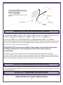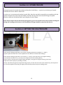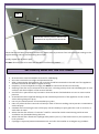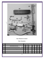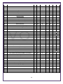
1
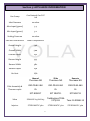
Vola 400HE Model Also known as: Apex, Blenheim, Grace, Daisy, Soho, Contemporary, Contemporary II, Caledonian HE, Mystique HE, Magma HE, SP Full-Depth, SP400HE, MX1HE, MX20, Maximum Full-Depth HE, Pinnacle Full-Depth HE Liberty Full-Depth HE and Lux Full-Depth HE Manual, Slide & Remote Control Installation and User Instructions All instructions must be handed to user for safekeeping This is not a DIY product and must be installed by a Gas Safe registered installer Edition A 07/13 Country(s) of destination - GB/IE 1 INSTALLATION INSTRUCTIONS These Notes Must Be Read Before Installation This appliance is an Inset Live Fuel Effect appliance that provides radiant or combined radiant and convected heat; it cannot and should not be used as the main heating source within a property. The appliance is designed to fit most types of fireplaces with a natural draught flue as listed in the Installation Requirements. The appliance must be installed by a competent person in accordance with the Gas Safety (Installation and Use) Regulations 1998. A Gas Safety Registered installer must be used for this purpose. Read all these instructions before any installation takes place and in conjunction with the appliance on site. This appliance must be installed in accordance with the rules in force and only used in a sufficiently ventilated space. This appliance is factory set and tested for operation on the gas type, and at the pressure stated on the appliance data plate. After a new gas appliance (excluding flueless cookers) has been fitted, the Building Regulations in England and Wales require that the installation must be notified to your Local Authority. Your Gas Safe registered engineer needs to do this, failure to register the appliance may affect your warranty. 2 OPENING THE APPLIANCE Stand the carton the right way up, open the box from the top. To remove the appliance lift by the handle secured to the top. Once the appliance is out of the carton remove the handle and replace screws back in the holes Read all the instructions before continuing to unpack or install this appliance. Remove the bags containing ceramic components such as coals or gravel etc. Remove the cardboard packing pieces, and any other bags or boxes containing fittings or other parts, when all loose parts have been removed, the appliance may be lifted from the outer carton. Check that the components supplied correlate with the component checklist below. If for some reason any of the listed components are missing or damaged do NOT commence with this installation, in doing so will invalidate your warranty. Please dispose of all the packaging materials at your local recycling centre. 3 CONTENT CHECK LIST Quantity 1 1 1 1 1 1 1 1 1 1 3 Description Firebox and Burner Tray Decorative Trim/Frame Fire Fret/Front Rear Matrix/ Fuel Bed support Front Matrix/ Fuel Bed support Coals/Pebbles Bag of (9 or 14) Ceramic brick panel. Cable fixing kit; 1 cable, 2 tensioners, 2 cable clamps, 3 fixing eyes. Lengths of adhesive sealing strip. Set of manufacturer’s instructions and warranty card. Raw Plugs INSTRUCTION CONTENT Section 1 2 3 4 5 5.1 6 7 7.1 7.2 8 9 10 10.1 11 12 13 14 15 16 17 18 19 20 Contents Important Notes Installation requirements Appliance Information Ventilation Site Requirements Pre-Fabricated Flue box Debris Space Installation of appliance Preparing the Opening Fitting the Burner Tray Fuel Bed Fitting The Outer Frame/ Trim Commissioning the Appliance Spark Failure Setting Pressure Spillage Monitoring System Testing for Spillage Briefing the Customer Servicing Cleaning the Coals Troubleshooting Guide User Instructions Warranty Details List of Spares Contact details 4 Page No 5 6 7 8 8 to 9 10 11 11 to 12 15 to 17 18 to 20 21 to 27 27 27 28 28 29 30 31 32 33 33 to 36 37 44 45 to 51 51 Section 1: IMPORTANT NOTES This fire is an Inset Live Fuel Effect Gas Fire providing radiant warmth. It is designed to operate on Natural Gas or LPG. It is the LAW that all gas appliances and fittings are installed by a competent person such as a Gas Safe Registered fitter and in accordance with the Gas Safety (Installation and Use) Regulations 1998, the relevant British Standards for Installation, Codes of Practice and in accordance with the manufacturers’ Instructions. The installation shall also be carried out in accordance with the following regulations: The Building Regulations issued by the Department of the Environment, the Building Standards (Scotland) (Consolidation) Regulations issued by the Scottish Development Department. BS 1251 BS 4543 part2 BS 5440 parts 1&2 BS 5871 part 3 BS 6461 parts 1&2 BS 6891 BS 8303 Failure to comply with these regulations could lead to prosecution and deem the warranty Invalid. This appliance must be installed in accordance with the rules in force and used only in a sufficiently ventilated space. Consult all instructions before installation and use of this appliance. The appliance must be registered once commissioned with the regulatory governing body. This appliance is free from any asbestos material. Refractories and coal bed are constructed from ceramic fibre. Note - For Republic of Ireland, reference should be made to the relevant standards governing installation, particularly in regard to flue sizing and ventilation. See IS813, ICP3, IS327 and any other rules in force. 5 Section 2: INSTALLATION REQUIREMENTS This appliance MUST NOT be installed into a bathroom or shower room, or where steam may be present. An extractor fan must not be fitted in the same room or space as the appliance as this can affect the safety of the appliance. The fire has been designed to fit into a fireplace or builders opening conforming to BS 1251 (and meeting certain dimensional requirements), or a suitable flue box complying with the constructional requirements of BS 715. A natural draught flue system is required, and if previously used for solid fuel or oil burning, the flue and chimney must be swept prior to appliance installation. The flue must be checked before installation by using a smoke pellet or similar to ensure proper draw and that leakage is not evident at any joints. Repair and re-test as necessary before the appliance is installed. Any flue box used must be installed onto a suitable non-combustible insulating surface at least 12mm thick, covering the entire base area of the box. The flue must have an effective height of at least three metres, as measured from the hearth to the top of the flue. Any flue damper plates or restrictors must be removed and no other restriction fitted to the flue. Where removal is not practical, the restriction must be fixed in the fully open position. The flue must be connected to only one fireplace, and the flue must not vent more than one appliance. There must be no opening in the flue apart from the one that the appliance is installed into, and the one venting the gases into the air. A suitable terminal may be fitted, such as class GC1, as regulations allow. Some of our appliances have been tested for use in a pre-cast block flue complying with BS 1289. In accordance with BS1289 part 1, pre-cast flues built with directly plastered faces (front or rear) are not correctly installed as to ensure proper operation with any type of gas fire. Depending on the flue construction, on occasions the temperature reached can cause cracking of the surface plaster through no fault of the appliance. An air gap or some form of insulation material should be installed to prevent normal flue temperatures from damaging wall surfaces. This appliance is suitable for use with a surrounding area or back panel of 150C minimum rating. 6 Section 3: APPLIANCE INFORMATION Gas Group G20 Natural Gas CAT I2H Inlet Pressure 20 mbar Max Input (gross) 5.3 Min Input (gross) 3.2 Setting Pressure 20 mbar Gas Inlet connection 8mm Compression Overall Height 596 Overall Width 500 Overall Depth 252 Recess Height 555 Recess Width 382 Recess Depth 250 Air Vent N/A Manual Thermaco NG Slide Thermaco NG Remote Thermaco NG OXI-PG-82-460 OXI-PG-82-460 OXI-PG-82-460 Or Or Or SIT NG9017 SIT NG4711 SIT NG4711 Valve SEAGAS V4-78A A13 Teddingtons TESA 3173/011 Tesc 01-RF868-15 Injector STEROMATIC 360 STEROMATIC 360 STEROMATIC 360 Pilot Assembly & Thermocouple 7 Section 4: VENTILATION This Appliance does not normally require purpose provided ventilation. However, a second appliance operating within the same room or space must be taken into consideration when assessing ventilation. When commissioning the appliance spillage is detected, then amongst other problems there may be insufficient natural ventilation for correct operation of the flue. If spillage is detected with windows closed, but the appliance does not spill with the windows open, this demonstrates a lack of natural ventilation. If spillage is still detected with the windows open, the flue is at fault. Installation of an air brick is the best solution to lack of ventilation. Any ventilation fitted must comply with BS 5871 part 2 and BS 5440 part 2. Air Vents fitted under or within the immediate vicinity of the appliance must not be used as adverse effects to the operation of the Flame Safety Device (FSD) may occur. Spillage detected during commissioning is almost always a result of poor flue performance that cannot be corrected by any amount of ventilation. For Republic of Ireland ventilation may be required, see IS 813, ICP3, IS 327, and any other rules in force. Section 5: SITE REQUIREMENTS The fireplace opening should be inspected and repairs made where necessary. A chair brick or fireback may be left in place, providing that the dimensional requirements for debris collection space and spigot clearances are met. See diagram below. This appliance requires a natural draught flue system which may be one of the following; 225mm x 225mm (9in x 9in) brick or stone 125mm (5in) minimum diameter lined brick or stone. 125mm (5in) minimum diameter twin wall flue must conform to BS 715. Any existing draught device situated under the fireplace must be sealed off. The opening area must be non-combustible. The appliance requires a hearth with non-combustible surface of at least 300mm in depth and 12mm thick. The top surface must be at least 50mm above the surrounding flooring level, or be surrounded by a raised edge or fender 50mm high. To enable the product of combustion to be cleared properly up the flue, the outlet at the back of the appliance must have a 50mm minimum clearance between it and the back wall of the opening or any other obstruction, the area immediately above the outlet must form a smooth path into the flue. The fireplace or builders open must be reduced to suite the appliance both side to side and the full depth of the appliance, a decorative back panel i.e. marble, granite etc. must not be used as a closure plate for the appliance please see below. 8 TOP VIEW Any type of fire surround used with this appliance must be adequately sealed to the wall and floor; a combustible shelf may be fixed to the wall above the fire, providing that it complies with the dimensions given below. From Hearth to Underneath of Shelf with a depth of 150mm is 800mm add 12.5mm in height for every 25mm increase to the projection of the shelf depth. Any combustible side walls must be at least 500mm to the side of the radiant heat source, as with all heating appliances, any decorations, soft furnishings, and wall coverings (i.e. flock, blown vinyl and embossed paper) positioned too close to the appliance may discolour or scorch. Diagram 1 Vola FD 400 HE A B C D E F MM Height 555-575mm Width 382-415mm Depth 250 Minimum Hearth Depth in Front of the Fire 300mm Heath must Extend Minimum of 150mm Minimum Hearth Height 50mm B A D C E 9 F Hole-in-the-wall installations Where the appliance is to be installed as a hole-in-the-wall fireplace, a hearth as previously detailed for floor level fireplaces shall be fitted on the floor beneath the hole so as to protect combustible material from heat. However, if a hearth is not to be used, so as to maintain a minimal and contemporary look, the appliance must be installed so that every part of any naked flame or incandescent part of the fire bed is at least 300mm vertically above any carpet or floor covering. When no hearth is to be fitted consideration must be given to fixing a tactile barrier to protect young children, the elderly and the infirm. A tactile barrier can be in the form of a fender, kerb, hearth, shelf or horizontal bar all made from noncombustible material and fixed not less than 50mm & not more than 1000mm above the floor level. They should be positioned not less than 300mm in front of the appliance. Section 5.1: PREFABRICATED FLUE BOXES This appliance can be fitted into a number of flue boxes provided that the minimum dimensions required for the appliance complied with. The frame of the fire, any back panel or other infill panels, and the flue box must be sealed together so that there is no possibility of leakage between them. The correct clearances to combustible materials (i.e. false chimney breast etc.) must be adhered to. The manufacturers’ instructions for fitting the prefabricated box must be complied with at all times. To fit the fire using the cable fixing kit supplied, some minor adaption may be necessary for certain flue boxes. Please ensure the firebox does not obscure the flue box outlet. The firebox, base of the flue box, and hearth below may be drilled to allow plugs and screws to secure installation. It is important that the sealing requirements of the appliance are met at all times and that the flue box is sealed to any back or infill panel. Note: The DEPTH dimension is inclusive of any back or infill panel. Section 6: DEBRIS SPACE In accordance with BS 5871 part 2, minimum debris collection volumes are required behind the installed appliance. CLAY/CEMENT LINES OR BLOCK FLUE WHICH IS NEW, UNUSED, OR PREVIOUSLY ONLY USED WITH A GAS FIRE. Appliance recessed depth + 20mm UNLINED FLUE OR CHIMNEY WHICH HAS BEEN PREVIOUSLY USED FOR A SOLID FUEL OR OIL BURNING APPLIANCE Appliance recessed depth + 60mm 10 Section 7: INSTALLATION OF THE APPLIANCE Always ensure that the gas supply is isolated before commencing installation of the appliance. The fireplace opening and environment must be in compliance with specifications laid down in the appropriate sections of these instructions. Remove the appliance from its carton as described previously and stand on a dust sheet, place the coals, ceramics and fixings safely to one side. Remove the burner from the assembly by removing the two screws at the base of the burner tray and undoing the connecting nut to the isolation tap. Unsecure the glass panel from the box as shown below, Remove outer cover to the glass Panel. Remove the manual burner from the assembly by removing the two screws at the base of the burner tray and undoing the connecting nut to the isolation tap. ISOLATION TAP SCREWS Now, remove the 2 screws on the top of the burner tray. 11 The tray is now free and may be lifted away from the box, lift free of the firebox. On the slide control option disassemble the linkage by removing the 3 screws (shown in diagram below), to the slide control then remove the burner from the assembly by removing the three screws at the base of the burner tray and undoing the connecting nut to the isolation tap on the side. Remove the 2 screws on the top of the burner tray. 12 The tray is now free and may be lifted away from the box, lift free of the retaining clips on each side of the burner tray. If this is the slide controlled version of the this fire then care is needed when removing the burner not to damage the wiring system of the fire, you will need to remove the Heat Shield and Carefully remove the spark generator from the box or remove the cables to the generator, making a note of which cable goes where on the battery holder placed at the back of the fire box. If this is the Remote controlled version of this fire then care is needed again when removing the burner not to damage the wiring system of the fire. 13 Diagram 5 You can now decide where to route your gas pipe, knock out holes are provided in the rear and side of the fire box for use where concealed pipe work is required. Knock out the holes with a screwdriver and a sharp tap from a hammer and fit the rubber grommet supplied. The position of the isolation tap may change depending on the model being fitted. Note: DO NOT install or use the appliance without this seal in place, Failure to fit this seal correctly will cause the flue suction to act upon the area under the burner tray resulting in poor performance, and overheating of this area. Section 7.1: INSTALLATION OF THE FIREBOX Before installing the fire, check the flue for correct operation using a smoke pellet, all of the smoke should be drawn up the flue and exit correctly from the terminal. If problems are found DO NOT fit the fire until corrective measures have been completed. Protect the decorative hearth whilst pushing the convector box in and out of the opening. Part of the packaging or a dust sheet can be used. Before running the gas supply into the opening, offer up the convector box to the fireplace to check the fit is good. Ensure that it slides in correctly, the sealing face sits flat and square to the wall or back panel, and that the base level with the hearth as no leaks are permissible here. At this stage it is essential to ensure that the spigot outlet of the fire is not obstructed in any way. Remove the fire box and apply the self-adhesive sealing strips around the edge of the rear of the firebox frame, approximately 5mm in from the edge. CABLE FIXING: Using the template provided, place this within the opening with the bottom edge of the template level with the hearth. 14 Drill 4 x 6mm holes through the template as shown in the diagram and fit the Rawlplugs and screw eyes supplied. Screw Eye Positions 203mm Diagram 6 520 Max 550mm 420 Min 100mm Note: In some instances the plastic Rawlplugs supplied my need to be substituted with fibre rawlplug's, if the appliance is likely to heat the screw eyes. If the fireplace does not allow for the exact layout shown, the eyebolts should be fixed to give a similar configuration as possible. Thread the tensioning cable through the holes at the top of the firebox, then through the two screw eyes in the top position and then through the one at the lower position, back through the lower hole in the firebox as shown in the diagram. Open out Tab’s with screwdriver to except the cable tie 15 Through holes at the top of the fire box Through Screw eyes Through Screw eye at the bottom and through the 2 holes near base of the firebox Push the appliance back into the fireplace, centralise and pull the loose cables through the holes into the firebox, thread the cable tensioners onto the cable as shown, with the nuts screwed down close to the tensioner head. Slide the screwed nipple through the box and pull cable taut and tighten pinch screw on to the cable. Pinch screw Tension nut Adjust tensioner using a suitable spanner to pull the cable tight into position, to allow an even seal around the edge of the fire, visually inspect the seal and reseat if necessary. 16 Surplus tension cable MUST NOT be cut off as this will prevent proper installation after servicing simply coil up the surplus cable as shown and tuck the coils out of the way. Fixing by screw: Mark and drill the fire frame or base, and relevant points in the opening or on the wall. Raw plugs will be required. Note: Fibre Rawlplugs might be preferred rather than plastic Rawlplugs as the heat from the fire might affect their efficiency. Whilst the opening is ready for installation of the fire, the gas supply can be routed as required and connected to the isolation tap via the 8mm compression fitting. Note: In no circumstance should you use soft soldered connections to or underneath the burner tray. Section 7.2: FITTING THE BURNER TRAY Temporarily fit the burner tray and ensure a suitable gas route can be achieved. If the fire is the manual control system, you can now place the burner tray into the firebox making sure that the fixing points are locate properly on the firebox. Fit the two securing screws through the front plate ensuring that the plate is in correct position in the box; secure the two screws at the back of the tray. Connect the gas supply and tighten the gas connections. With the slide control option please reverse the previous removal instructions taking care to a line the linkage system as shown below. 17 The battery can now be fitted to the extension lead provided and placed within left hand side of the spacer. Remote Control options will need the 3 x AA batteries (Batteries are not included, Plus Lithium type batteries can be used) these are to be placed under the battery compartment cover. 18 Section 8: FUEL BED LAYOUT Place the ceramic middle matrix onto the burner ensuring that is sits flat on that base plate and the front is behind the burner. Place the rear matrix behind the middle matrix and again ensure it is sitting flat on the base plate of the burner. Place front matrix coal support into the front shelf support brackets. 19 Place the front row of 6 coals between the front coal support and the middle matrix as shown. E E E E 20 U T Now Place the second row as shown below. A E E E A A Note: The coals must not be crammed together, or inserted into the holes in the matrix, Pay special attention to finally adjust the coals with the fire lit on the HIGH setting in order to ensure that no flames play onto the firebox sides or glass, you may need to place the glass in position and then make the final adjustments to obtain equal flame picture without touching the glass. 21 Section9: FITTING THE DECORATIVE FRAME The appliance is supplied with a decorative frame, the frame attaches to the firebox as a three piece or one piece clip-on unit. Place the magnets supplied to the outer frame of the fire box. A plastic protective coating may be applied to the face of the frame assembly, which should be removed at this stage; the one piece unit can be placed in position, with the three piece unit you should start with the side pieces of the clip-on assembly, these should be pushed into position first, followed by the top bar, which should overlap the sides. IMPORTANT NOTE: Due to the possibility of sharp edges, care should be taken when handling the three piece frame components, the use of protective gloves is recommended. Place the fire front/ fret into position in front of the fire and slide the ashpan door into place. The fire front/fret shown in these instructions may differ from the one supplied with the appliance, we strongly recommend you use a fire front/fret supplied by Sirocco fires as these products will have been tested with the appliance, although other fire front/frets will be compatible. Section 9: COMMISSIONING THE APPLIANCE Turn on and test the gas supply up to the fire for any leaks, in accordance with current Approved Codes of Practice (ACOPs) Section 10.1: OPERATING THE APPLIANCE (See Section 18: Users Instructions) 22 Section 10.2: SPARK FAILURE The gap between the spark electrode and the pilot should be 3.5 - 4.5mm to produce a good spark. There should be no need to adjust this. If under any circumstances the electric spark fails, the pilot may be lit manually by proceeding with the ignition sequence as previously described, and after turning the control knob through the spark position, the knob should be held in and the pilot lit with a taper. Note: Please ensure that the electrode spark igniters’ gap on the manual version has not been misaligned during the handling of the burner in this installation the gap should be 5mm from the burner. Section 11: SETTING THE GAS PRESSURE Remove the pressure test point sealing screw from the isolation elbow and attach a suitable pressure gauge. Check that the inlet gas pressure is at 20 mbar / Working Pressure at 20 Mbar (+/- 1 mbar) Light the pilot and check the correct operation of the burner at all the flame settings. Check that the inlet gas pressure is at 20 mbar (+/- 1 mbar), when the fire is at its highest setting. Once the fire has been lit for 5 minutes, turn the gas OFF at the isolating elbow. After a further 3 minutes turn the gas supply ON again, if the gas has stopped flowing, the Flame Supervision Device (FSD) is operating correctly. Always check that the gas has stopped flowing even if you hear the FSD valve close within the 3-minute period. Turn OFF the appliance and the gas supply and refit the pressure test point sealing screw. 23 SECTION 12: FLUE SPILLAGE MONITORING SYSTEM This fire is fitted with a flue spillage safety device (ODS), if the fire shuts down during use for no apparent reason then several things may be suspected, if a door or window has been opened creating a draught, then pilot disturbance is the problem, and removal of the draught should resolve this. The gas pressure reaching the fire must also be checked (again, recalls your installer to check and rectify any problem). The thermocouple connection into the back of the gas control valve may also have worked loose during installation, simply get the installer to tighten. If pilot disturbance is not the cause, then the ODS safety system may be in operation. Switch the appliance OFF, check the flue and carry out any remedial work required. Relight the fire and carry out a spillage test, DO NOT allow the appliance to be used if it continues to fail a spillage test. The aeration hole of the pilot must be carefully cleaned out on each annual service to ensure continued function of the ODS. The spillage monitoring system shall not be adjusted, modified, or put out of operation by the installer. Any spare parts fitted MUST be of a type supplied for the purpose by the appliance manufacturer. If the fire is not spilling, then further guidance should be sought, using the Troubleshooting section as a guide. SECTION 13: TESTING FOR SPILLAGE CHECKING FOR CLEARANCE OF COMBUSTION PRODUCTS Close all doors and windows in the room. Light the fire and allow to run for approximately 5 minutes on high position. After approximately 5 minutes, hold a smoke match just inside and below the centre of the lower front edge of the top of the fire, as shown below in Fig 1. All smoke generated should be drawn back into the flue, If slight spillage occurs or if in doubt, repeat the test after a further 5-10 minutes. If the test indicates that spillage is occurring and the flue restrictor baffle has been fitted, it should be removed and the test repeated after the fire has cooled, if spillage persists, the flue is not functioning correctly and a fault exists. If, after investigation the fault cannot be traced and rectified, the fire must be disconnected from the gas supply and expert advice obtained. After ensuring that the fire is safe to use it should be left on high position to fully warm up. During this time a slight odour may be noticed, this is due to the "newness" of the fire and will soon disappear. 24 FIG 1 Hold smoke match in position 10mm inside and down from top face of the central slot When the test has been completed satisfactorily, repeat with any extractor fans in the premises running on the highest setting, and any communicating doors open. Finally, repeat with all doors open. DO NOT allows the fire to be used until the test is satisfactorily passed. SECTION 14: BRIEFING THE CUSTOMER All instructions must be handed to the user for safekeeping. Show the customer how to light and operate the fire. After commissioning the appliance, the customer should be instructed on the safe use of the appliance and the informed for the need of regular servicing. Frequency of service depends on usage, but MUST be carried out at least once annually. Cleaning of the fire may be achieved when the fire is cold using a damp cloth and mild detergent on most surfaces, with the exception of the ceramic fuel bed. A soft brush i.e. paint brush may be used to clean the ceramic fuel bed taken care not to use excessive pressure. Scratched and other superficial damage to the matt black paintwork of the appliance can be covered with matching heatproof spray. Use only the manufacturers’ recommended spray paint. Paint only when the fire is OFF and cold. Always mask off the surrounding area to prevent contamination with overspray. Ventilate the room during the use of the spray. DO NOT attempt to spray paint the coals or ceramics, or wash them in water. Advise that the fire will emit a “newness” smell for a time after initial commissioning and that extra ventilation may be needed during this time. Advise that the fire is fitted with a spillage safety device (O.D.S.). If the fire shuts down, this system may be in operation. If spillage is suspected, SWITCH APPLIANCE OFF and call in the installer to investigate any problems. 25 SECTION 15: SERVICING First Isolate the fire from the gas supply and ensure that the fire is fully cold before attempting service. Lay out the dust sheet and tools required. Remove the cast front fret. Carefully remove the ceramic components Remove the two screws that retain the tray in place and disconnect from the isolation tap. Remove the burner tray and other components as required (i.e. remote control box) Disconnect the gas supply, to the appliance and disconnect the isolation tap Remove convector box by, firstly protecting the hearth from potential damage, unroll the coiled tensioner cables from the rear of the firebox, remove the securing nipples and tensioner adjusters, the firebox is now released from the opening and can be slid outward onto the hearth. Check the fireplace opening for rubble accumulation and remove, if debris is excessive, initiate remedial work on the flue. Check the flue with smoke pellet for correct operation. Refit convector box using new seals where necessary Strip off the burner pipes and clean thoroughly. Clean out the injector, pilot assembly and burner tube. DO NOT remove the pilot injector. Re-assemble and re-fit the burner tray. Turn on the gas supply, and leak test. Refit the decorative casting and ceramics. Check any purpose provided ventilation is un-obstructed. Light the fire and test for spillage. Check setting pressure and safe operation of the appliance. SECTION 16: CLEANING THE COALS Remove the fire front/fret casting and place to one side. Remove the ceramic components. Gently clean in the open air using a dry paint brush. Be careful not to create dust from the coals. Where necessary replace damaged components with genuine spares. Seal scrap ceramic components in plastic bags and dispose at proper refuse sites as directed. Re-fit the coals by referring to the relevant section of these instructions. 26 SECTION 17: TROUBLE SHOOTING Manual and Slide Fire sparks but pilot Flame does not light? No gas to fire, check isolating valves are open. Pipe work blockage, clean out. Air not fully purged, re-purge supply or wait longer. Spark earthen to metal work, reset gap correctly. Blocked pilot, clean out internally. A pilot light but then goes out before main burner lights? Severe restriction in gas supply, clear obstruction. Faulty thermocouple, replace pilot unit. Hold control knob in for longer. Run through lighting system on the remote control several times allowing the valve to rest each time. Fire does not spark at pilot? HT lead detached, refit. Spark gap too large or small reset correctly. Spark shorting to metalwork under tray, re-align HT lead Fire runs for a time and then cuts off? Pilot flame shrinks when fire is on high? Fire smells when first lit or in use? Excessive room draught or flue pull, rectify. Loose or faulty thermocouple, rectify. O.D.S system in operation. Firebox grommet seal not fitted, rectify. Lint in pilot aeration hole, clean thoroughly internally Poor gas flow to fire, check pressure with fire on high. If pressure is low, remove any restriction in pipe work or valve. Check all isolators are adequately sized and fully open. Check meter pressure is adequate. Air leak under base of firebox, rectify. Lint in pilot aeration hole, clean thoroughly internally. Firebox grommet seal missing, rectify Newness smell from brand new appliance. Spillage occurring, call installer to carry out spillage test and rectify any problems. Low temperature sealants or combustible materials used in incorrect positions. Air leak under base of firebox, rectify Firebox grommet seal missing rectify. 27 SECTION 18: USER INSTRUCTIONS IMPORTANT NOTES The installation of this fire MUST only be carried out by a competent person (such as a Gas Safe registered fitter) in accordance with the Gas Safety (Installation and Use) Regulations 1998, the relevant British Standards, Codes of Practice, the Building Regulations and the manufacturers’ instructions. Failure to comply with the above recommendations could lead to prosecution and invalidate the appliance warranty. Please ensure you are handed all of the manufacturer’s documents on completion of the installation. This will include these instructions. Always keep a note of the installer’s name and address, the original purchase receipt and the date of installation for future reference. The fire and flue should be serviced regularly to ensure continued safe operation. See the servicing section for further details. Frequency of service will depend on use, but MUST be carried out at least once annually. Parts of this appliance become naturally hot during use. It is recommended that a suitable fire guard conforming to BS 6778 is used, especially where young children, the elderly, or infirm are concerned. Combustible items, such as flooring and furniture, and soft wall coverings (such as blown vinyl or embossed paper) may discolour if fitted too close to the fire. See relevant section for further details on clearances to combustibles. No combustible material or flooring should protrude onto the hearth. DO NOT burn any foreign material on this fire, the coals must be of the correct type and lay out in accordance with the relevant section of these instructions. Failure to do so could create a hazard or lead to sooting. Before the appliance is installed, the chimney should be swept. All flues should be checked by the installer to ensure there are no defects or obstructions that may prevent the flow of combustion products. The fire is only suitable for use with the gas type for which it is supplied. This fire is supplied with a particular style of fire front/fret. Use of the fire front/fret will ensure an adequate airflow under the fire bed for the correct functioning of this appliance. Compliance with safety standards cannot be guaranteed if another style of front is used. A combustible shelf may be fixed to the wall above the fire, providing that it complies with the dimensions given in section 3 site requirements. No purpose provided ventilation is normally required for this appliance. The requirements of other appliances operating in the same space or room, and the results of a spillage test must be taken into consideration when assessing ventilation requirements; this will have been carried out by your Gas Safe registered installer. For Republic of Ireland, ventilation may be required, see IS 813, ICP3, IS 327, and any other rules in for 28 SECTION 18.1: OPERATING THE APPLIANCE (Manual Control) For your safety, the fire is fitted with a Flame Supervision Device (FSD), which will shut off the Gas supply if for any reason the pilot is extinguished. This device incorporates a fixed probe, which senses heat from the pilot burner flame, if the probe is cooled, the device will prevent any gas flow. If for any reason the flames go out or if the fire has been turned off for any reason, always WAIT FOR 3 MINUTES before attempting to re-light. The pilot is visible through the Fuel bed at the front of the fire; rotate the coals for good viewing. Push in and turn the control knob to the SPARK position, and hold there for a few seconds. Continue turning anti-clockwise through the spark click to the PILOT light position, ensuring that the control knob is depressed and the pilot has lit. If not, return the knob clockwise, and repeat. LOW HIGH IGNITIO N OF F When the pilot lights after the spark, keep the knob depressed for approximately ten to fifteen seconds. Now release the knob and the pilot should stay alight. If the pilot is extinguished during use, wait three minutes before repeating the ignition procedure. To achieve the HIGH setting, push the control knob in slightly and continue turning anticlockwise to the high position. The main burner should light after a few seconds, to decrease the setting to LOW, turn the control knob clockwise to the low setting. To turn to the PILOT position from the HIGH or LOW positions, press the control knob in, and return to the pilot position and release. To turn the fire OFF, keep the control knob depressed, and return to the off position, then release. 29 SECTION 18.1: OPERATING THE APPLIANCE (Slide Control) For your safety, the fire is fitted with a Flame Supervision Device (FSD), which will shut off the Gas supply if for any reason the pilot is extinguished. This device incorporates a fixed probe, which senses heat from the pilot burner flame, if the probe is cooled, the device will prevent any gas flow. If for any reason the flames go out or if the fire has been turned off for any reason, always WAIT FOR 3 MINUTES before attempting to re-light. The pilot is visible through the Fuel bed at the front of the fire; rotate the coals for good viewing The battery can now be fitted to the extension lead provided and placed within left hand side of the spacer 30 1. From the standing position push the thumb control all the way to the bottom where a spark will be heard and generated, hold down for approximately 15 seconds. 2. Release the pressure and the pilot light should now be established (if this fails repeat step 1 and hold down for 20 seconds). 3. Slide the control upwards to increase the flame size to the desired effect. 4. To switch the fire off simple slide the control upwards, passed the positive stop and hold for 2 seconds. 31 SECTION 18.1: OPERATING THE APPLIANCE (Remote Control) IMPORTANT USER INFORMATION – AFTER INSTALLATION BY THE ENGINEER , READ THIS BEFORE ATTEMPTING TO OPERATE THE FIRE Insert the batteries in the TESC Control and handset as show inside the battery cover and slide isolation switch to the I position on the gas control. Hold the handset and the green unlock light will illuminate allowing the buttons to work. Press and hold in the power symbol button and release immediately when the word pilot appears at the bottom left of the display (after about 1-2 seconds). The fire will light. 32 To Adjust the flame hold the handset to enable the buttons to work and press and the button to reduce the flame. Press the + button to increase the flame. To stop the fire, hold handset to unlock the buttons and then press the power button. 33 Quick start user instructions Fire Control This control is situated on your fire. The drawing shows the main features of the control. The control required 3 x AA size alkaline batteries to be inserted under the battery compartment cover. The orientation of these is shown moulded into the battery compartment. After fitting the batteries and replacing the cover the fire can now operate. Slide the slide switch to the right to the ON position. To start the fire, press the power button and hold for 1 second then release. The burner will within around 1 to 2 seconds, adjust to the maximum power setting, The power of the burner can be adjusted up and down by pressing the – and + buttons. To stop the fire, simply press the power button again and the burner will stop. If you are not intending to use the fire for a long period (i.e. over summer time months), the battery life can be extended even more by sliding the white isolator switch to the left (away from the On position). Ensure the very small white slider switch on the front corner of Fire Control is in the on position. Grasp around the handset to unlock its functions. The green unlock light will illuminate to show when the handset is unlocked and ready to accept commands. (N.B. Keep a grip of handset to keep it unlocked, to continue to operate the command buttons.) For your safety, the fire is fitted with a Flame Supervision Device (FSD), which will shut off the Gas supply if for any reason the pilot is extinguished. 34 Mode In Range of the fire If missing out of range or fire switched off Man = Manual Zzz = Snooze Therm = Thermostat Timed Day of the Week Room Temperature Time (12 or 24hr) Fire Status Battery Indicator RC = Handset FC = Fire Control Handset Unlocked if Illuminated Light Sensor (for Display Backlight) To Change Settings see handbook To Change Mode Press to Decrease Flame To Increase Flame Power Button 35 Quick start user instructions Press the Power button to start the fire, (after ensuring the fire control is turned on as described above), with one hand grasp around the rear of both sides of the button area control. The green unlock light will illuminate. Keep it held to keep the control unlocked, to enable operation of the buttons. Then with the other hand touch and keep you finger on the power button for about 5 seconds. (Upon touching the power button the green light will do a single flash to show command is recognized – after 5 seconds the green light will flash for a second time, at which you should release your finger). The Fire should be lit within a few seconds. (N.B. If power button is held for more than a few seconds after second flash/beep, the command ignored for safety reasons. With this system, the control has been designed to ensure that only intended ignition of the fire occurs.) To stop – with handset held to unlock it, press then release power button. Operating instruction (Detailed) 1) Upon successful insertion of the batteries in the Handset (if the handset has not previously paired) the display will be as shown if it has been paired already then go to No 2) Pairing the Handset to the Fire Control (paired at factory only do if re-pairing) After fitting the batteries as above (and with the isolator slide switch on the TESC Fire control in the ON position), simultaneously press and hold the – and + buttons on the fire control (i.e. not the handset) 5- 10seconds – then LED on TESC lights – then within 2 seconds of LED light coming on, press the power (start stop ) button on TESC. The handset will beep and green light flash Hold the handset in one hand so your fingers wrap around the back of the operating buttons area of the handset. A green unlock light will illuminate when the handset has detected your hand. The green light must be illuminated in this way for any of the command buttons to accept commands to operate the fire control. Whilst the display is as shown, and holding the handset as described, press the “SET” button with the other hand to finish off the pairing of the handset to the Fire 36 Control and to enter to setup the time of day on the handset. N.B. If the display returns to the one shown above with the word “TESC” shown, then too much time has passed before pressing “SET” and so the handset has not paired yet. Simply repeat pairing again. Video available on You Tube Search for; TESC Gas Control - Display handset pairing 3) Setting the time Following pressing “SET” at paring above, the display will be as shown, as the time is not set yet and will progress automatically to the next screen shown below. Note: the indicator at the bottom shows the battery condition of both the batteries in the hand set and in the fire control within the fire. RC = Remote Control / FC = Fire Control. The control is designed to get the most out of the batteries but when eventually the display shows they are spent (when the battery indicator is empty, we recommend you change the batteries in the handset before they are flat, to avoid having to re-program the time of day in again. N.B. Pairing is not lost, even if the batteries are removed or flat. 4) Setting the display for 12 or 24 Hour display As always when pressing the remote control buttons keep the control held to keep the green light on and therefore handset safety feature, unlocked. The H indicates that it is time to set the timer to either 24 hour display or 12 Hour (AM or PM) display. Press the + or – button on the handset to toggle between the two settings. When you are ready to confirm the setting you want press the “SET” button to progress to setting the day of the week. 37 Setting the day of the week Press and release the + and – buttons until the correct day of the week is shown on the display. (Mo = Monday, Tu= Tuesday, We=Wednesday, Th=Thursday, Fr=Friday, Sa=Saturday and Su=Sunday). Press “SET” to accept the day of the week and to progress to setting the Hour of the day. Note: Whilst doing this setup pressing “SET” advances to the next display and pressing “MODE” will return you to the previous display setting. Setting the Hour Press and release the + or – button to change the hour to the correct hour and press set to store and to move to setting the minute. Repeat this for setting the minutes. Setting the temperature display to Celsius or Fahrenheit. Press and release the + or - button to toggle between C and F. 38 When the display shows the desired symbol, press and releases the “SET” button to store. As the important settings above have now been done. Press and hold (not releasing straight away) the “SET” button for a few seconds and this will exit the setup menu. The control is now ready for use with the Fire Control. Advanced settings Menu In the event that you may want to change the other pre-set settings of the control features. Do not do a long press and hold above but a normal short press and release will take you into the advanced settings area. Advanced settings options are:• Back light – o A = Automatic (default setting). The back light comes on in the dark but not in the light. o 0 = Light never comes on. o 1 = Light comes on whenever handset is unlocked. • Display contrast – 8 levels from 0 to 7 (default level 4). • P = pairing with other devices other than the fire control. The hand set can pair with other modules to:o L= Operate an electric light – which is the dimmable in 9 steps o F= operate an electric fan –which can have 9 speed levels o A= operate an auxiliary contact to operate another device. Note: Fitting the batteries incorrectly could lead to damaging your control box. Different types of batteries or old and new batteries are not to be mixed. Only batteries of the same or equivalent type as recommended are to be used. Batteries are to be inserted with the correct polarity. Exhausted batteries are to be removed from the fire. The supply terminals are not to be short-circuited. Do not use rechargeable batteries. Non-re-chargeable batteries are not to be recharged. Do not mix old and new batteries. Do not mix alkaline, standard (carbon zinc) or re-chargeable batteries. 39 GENERAL CLEANING Before carrying out any of the following operations, ensure that the fire is OFF and completely cold. Debris that may form on the fire bed should be periodically removed by a competent person. Large deposits could indicate deterioration of the flue. This should be repaired by a competent person, and the fire serviced before further use. FIRE FRONT/FRET - Any dust accumulating in the fire front may be removed using a vacuum cleaner or dry cloth. Heavy stains may be removed by using a damp cloth and mild household detergent. Brass parts of the fire front may be cleaned using a suitable brass cleaner. Replace the front centrally against the fire after cleaning. PAINTED AREAS - These can be cleaned using a dry cloth. GLASS - Remove the Glass panel as per the installation instruction and clean glass with a glass cleaner and a lint free cloth or Microsoft cloth, if white haze or carbon discolouration is still apparent the a metal polish such as Hotspot or Peek can be used to remove these stubborn particles. SECTION 19: WARRANTY IMPORTANT INFORMATION ABOUT WARRANTY SERVICE FOR THE END USER WARRANTY REGISTRATION IS REQUIRED WITHIN 28 DAYS FROM DATE OF PURCHASE It is in your interest to register your appliance with Sirocco as soon as possible BEFORE CONTACTING SIROCCO FOR SERVICE PLEASE READ THE FOLLOWING; Sirocco is committed to customer care and service. To ensure we provide the best service we can we have a policy to charge for all none warranty home visits so that all customers with a genuine manufactures fault can be dealt with swiftly, if your appliance has recently been installed and you are experiencing any of the following; Fumes are spilling from the flue/fire The pilot light cuts out after a few minutes The fire controls are getting too hot Excessive sooting is forming on the fuel bed Poor flame picture Remote controls are not working These symptoms tend to be chimney/flue or installations related and as such mostly are not covered by your warranty and are mostly dealt with in the installation instructions, DO NOT USE YOUR APPLIANCE and in the first instance contact your installer to investigate these further, to establish their cause before contacting Sirocco. CONTACTING SIROCCO FOR WARRANTY SERVICE OR TO PURCHASE SPARE PARTS In the event of a service or parts claim please note that some parts such as ceramics, batteries, trims and fronts etc. are categorized as “user serviceable parts’ and are not carried out by a service visit. 40 Please ensure you have the following information at hand when you contact Sirocco; The full serial number which is located on the data badge of the appliance Your receipt of purchase showing the date and where purchased from Your installers details You can contact Sirocco`s representative in the UK by phone to obtain advice and a warranty service form on; 0843 289 4268 Or you can complete a form on line at www.siroccofires.com follow the link at the top right hand side on the home page. SIROCCO Sp. Zo.o Nad Lasem 8, Zelecow, 96-321 Zabia Wola, Poland. Tel 0048 22 425 8681, Fax 0048 46 857 8559. Further information, contact details and email facilities are available through our website; www.siroccofires.com SECTION 20: LIST OF SPARES Eco 2 Manual Control 41 Eco 2 Slide Control 42 Eco 2 Remote Control Eco2 Ceramics Code SPARE PART DESCRIPTION PARTNUMBER CERAMICS 1A FRONT MATRIX BLACK HEFD PRT CER MX/F HEFD 1 BLK 2A REAR MATRIX BLACK HEFD PRT CER MX/RE HEFD 1 BLK 3A COAL SET HEFD (17 PCS) PRT CER CO HEFD 1 BLK 4A PEBBLE SET (mixed 17 pc) PRT CER PB HEFD 1 MIX 5A PEBBLE HEFD FRONT MATRIX PRT CER MX/F/PE HEFD 1 GRE 6A PEBBLE HEFD REAR MATRIX PRT CER MX/RE/PE HEFD 1 GRE 7A CERAMIC LINING SET PRT CER LIN HEFD 1 BLK 9A 43 FIXING KIT PRT FIX FK HEFD 0 SI 0 INSTALLATION & USER MANUAL ALL MODELS PRT DOC IM HEFD 0 SI 1M TRIM 3 PART BRASS PRT DCF TR ECO 3PR SK BR TRIM 3 PART CHROME PRT DCF TR ECO 3PR SK CH TRIM 3 PART BLACK PRT DCF TR ECO 3PR SK BL MANUAL OPTION B1 PILOT NG THERMACO NG OXI-PG-82-460 PRT VAL PI RO PL SIT 1 B2 BURNER (NATURAL GAS) PRT VAL BR HEFD NG SIR 0 B3 INJECTOR (NATURAL GAS) PRT VAL IJ HEFD BRAY 360 NG B4 4mm Pilot inlet tube PRT VAL TU HEFD M SI PI B5 8mm Gas Inlet tube PRT VAL TU HEFD M SI INL B6 GAS CONTROL VALVE V4-78A A13 PRT VAL CV ST 0 SG 0 B7 8mm Burner pipe PRT VAL TU HEFD UN SI BT B8 ISOLATION/PRESURE TEST POINT VALVE INC NUT & OLIVE PRT VAL IS UNI 0 PR 0 B9 CONTROL VALVE KNOB (PACK X 2) PRT VAL KN UNI 0 MUL 15 B10 ENGINE (MANUAL) EXCLUDING CERAMICS PRT INS HEFD N M 1C ENGINE (REMOTE) EXCLUDING CERAMICS PRT INS 6C REMOTE HAND SET PRT VAL 7C ACS2 LP VALVE PRT VAL 8C PILOT GAS TUBE 4MM PRT VAL 9C GAS INLET TUBE 8MM PRT VAL 12C PILOT NG THERMACO NG OXI-PG-82-460 PRT VAL PI RO PL SIT 1 13C 8mm BURNER INLET TUBE PRT VAL 15C BURNER (NATURAL GAS) FOR REMOTE CONTROL PRT VAL BR E2 NG AE 42R 16C INJECTOR (NATURAL GAS) PRT VAL IJ HEFD BRAY 360 NG E - 0 SLIDE CONTROL OPTION 1D ENGINE (SLIDE) EXCLUDING CERAMICS PRT INS HEFD N SL E - 0 2D SLIDE CONTROL MECHANISM ASSEMBLY C/W LINKAGE PRT VAL SL UN MC SI 1 3D PILOT GAS TUBE 4MM complete with nuts & olives PRT VAL TU PI SL SI HEFD 4D GAS INLET TUBE 8MM complete with nuts & olives PRT VAL TU IN SL SI HEFD 5D PILOT NG THERMACO NG OXI-PG-82-460 PRT VAL PI RO PL SIT 1 7D GAS INLET TUBE 8MM C/W INLET ELBOW, NUTS & OLIVES PRT VAL TU IN SL SI HEFD 8D INJECTOR (NATURAL GAS) PRT VAL IJ HE4 BRAY 360 NG 9D BURNER (NATURAL GAS) FOR SLIDE CONTROL PRT VAL BR HEFD NG SIR 1 10D H T LEADS X3 for spark generator PRT VAL SL UN NG SI 1 11D SPARK GENERATOR PRT VAL SG UN NG TC 1 12D MICRO INTERRUPTER SWITCH PRT VAL IS UN 0 BC 2 13D TEDDINGTON VALVE 3173/011 PRT VAL SL UN 0 TED 1 14D LINK PLATE PRT VAL SL UN 0 HS 1 15D LINK ROLLER WHEEL PRT VAL SL UN 0 HS 2 44 SECTION 21: CONTACT DETAILS SPARE PARTS If you need assistance or wish to purchase spare parts 08432 890102 Mon to Fri 9:00 to 16:00 Contact our spares department by email [email protected] Purchase spare parts direct from our website www.siroccofires.com Spare parts are managed by our UK partner company Lodestar-Delta Ltd Lodestar-Delta Ltd T/A Sirocco Unit 1, 11 Weir St, Blackburn, Lancashire BB2 2AN SIROCCO HEAD OFFICE Telephone number for all departments 0843 289 4268 (charged at BT national rate) Mon to Fri 10:00 to 15:00 Contact us by email [email protected] View our latest products and use our on line services; www.siroccofires.com Nad Lasem 8, Zabia Wola 96-321 Zelechow Poland TECHNICAL HELP LINE Speak to a Sirocco trained engineer 0904 0843473 (0904 084 FIRE) This is a premium rate number charged at 1.00 plus vat per minute from BT lines Mon to Fri 9:00 to 17:00 WARRANTY AND SERVICE For warranty registration or for a home service call: www.siroccofires.com For assistance to complete a registration or a home service Call us on 08432-890102 Mon to Fri 9:00 to 16:00 Our warranty statement 45 CONDITIONS OF GUARANTEE Sirocco (hereinafter referred to as the company) will, at its option, repair or replace free of charge any product or part thereof which is shown to the satisfaction of the company to be defective due to faulty materials or workmanship within 12 months from the date of purchase, subject to the conditions set out below: 1. Gas fire installation and commissioning must be carried out by a GAS SAFE registered engineer that has a valid and relevant qualification to work on such appliances in accordance with the installation instructions supplied with the product. 2. The warranty registration form must be correctly completed and returned to Sirocco within 28 days from date of purchase 3. 4. 5. A valid and correctly completed installers Commissioning Declaration form (as supplied in the warranty registration form) relating to the installation of the product must be presented to the company in respect of any claim under this guarantee. A CP1 form must be completed on commissioning the appliance and registered with GAS SAFE The product must only be operated in accordance with the user instruction book. 6. The installation must be in accordance with the installation instructions and comply with all current legislation and building regulations. 7. The guarantee commences from date of purchase. A proof of purchase is required as part of the validation to receive a warranty service. A sales receipt showing the original date of purchase is considered proof of purchase no other documentation will not be accepted. 8. The guarantee shall not cover any fault or defect caused by faulty installation, including failure to observe the installation instructions supplied with the product. Accordingly the company will charge a fee to cover the cost to the company of travel and/or time spent to rectify a product which is incorrectly or improperly installed and for any parts that may have been so damaged due to this. The company will advise the amount of such fee and take your credit or debit card details prior to our engineer’s visit. The fee will be charged to your credit or debit card if the defect is other than a manufacturing fault. 9. The guarantee is non-transferable and is made to the first retail purchaser provided that the sale is made through an approved company stockist. 10. Any installation labour transportation or other related costs/expenses arising from defective parts/rapier replacement or otherwise of same will not be covered by this guarantee nor shall the company assume responsibility for same. Furthermore the company shall not be responsible for any indirect or consequential damages except as provided by law. 11. The appliance must be kept free from dust, dirt and debris by the user, in accordance with the cleaning instruction 12. All other guarantees expressed or implied with respect to the product, its components, and accessories or any obligations/liabilities on the part of the company are hereby expressly excluded so far as permitted by law. 13. The company neither assumes nor authorises any third party to assume on its behalf any other liabilities with respect to the sale of the appliance. 14. The guarantee does not apply to other non-Sirocco products such as prefabricated flue boxes and flues. 15. The company will not be responsible for: (a) Inadequate or inappropriate flueing, chimneys etc.; (b) down drafts or spillage caused by environmental conditions such as nearby trees, buildings, rooftops, hills or mountains; (c) inadequate ventilation or negative air pressure caused by mechanical systems such as extraction fans, cooker extraction hoods, clothes driers etc. 16. The guarantee is void if: (a) the fire has been operated in atmospheres contaminated by chlorine, fluorine, or other damaging chemicals; (b) the fire is subjected to long periods of dampness or condensation. 17. The guarantee shall not cover: (a) any damage to the combustion chamber or the heat exchanger or other components due to water or weather damage which is the result of, but not limited to improper chimney/venting installation; (b) any fault or defect caused by failure to observe the user instructions supplied with the product or by any alteration, modification, wilful abuse, accident, careless operation or miss-use of the product or by any external sources e.g. transit damage or weather.. 18. The guarantee will not cover an appliance that has been found damaged or incomplete prior to installation but is there after installed without being corrected by sirocco beforehand or removed from the installation prior to Sirocco inspecting. 19. The guarantee will not cover an appliance that has been subsequently removed without Sirocco having the opportunity to inspect the appliance or without the prior written consent of Sirocco 20. Validation of your installation will be required prior to warranty service/repair; there will be a fee for this. No other validation will be accepted by Sirocco. 46 21. The guarantee shall not cover: (a) surface crazing of fibre components e.g. matrix, coals liners etc.; (b) batteries; (c) cosmetic blemishes to polished metal and painted surfaces. 22. Some components are categorised as “user serviceable parts” and will not be carried out as a service visit, these include ceramic components, decorative trims and fronts, batteries, some electrical and electronic components etc. 23. Repairs carried out under the guarantee do not extend the guarantee period. Any parts removed during guarantee repairs become the property of the company. 24. The guarantee is in addition to, and does not affect, your statutory and other legal rights. In Addition to the above the following terms and conditions apply to extended 5 year warranty; 25 Extended 5 year parts warranty has to be issued by an appointed Sirocco Premier stockiest, no other stockists are authorised to issue these warranties 26 The warranty approval number issued by the stockist must be entered at the time of registration (this can be completed on our website) 27 The extended warranty gives an addition 4 years parts only warranty commencing from the 1 st anniversary of the date on purchase, this is limited to the repair or replacement of parts found to be defective in material or workmanship only after confirmation of the defect by a Sirocco engineer or an appointed Sirocco engineer, provided that such parts have been subject to normal conditions of use 28 Any installation, labour, transportation or any other related or expenses arising from defective parts, repair or otherwise of the same are not covered by this warranty, nor shall Sirocco assume responsibility for any incidental indirect or consequential damages, except as provided by law. 29 It is essential that your Sirocco appliance is serviced, by a suitably qualified Gas Safe engineer or a Sirocco authorised appointed engineer to carry this out at least every twelve months, as part of your 5 year warranty in addition the flame failure devise or ODS and ceramics on some models will need to be replaced in the 3rd year service as part of the conditions of your 5 year warranty, these items are purchased from the Sirocco internet website “Spares shop” and are shown as 3rd year service packs, the invoice for these items must be provided at the time of making the claim. 30 The service log found in the installation instructions must be completed by the service engineer at the time of the service and an appropriate invoice issued for this and supplied to Sirocco on any claim being made under the warranty 31 The following are not covered by this extended warranty: paint work in the fire chamber, fire fronts, and decorative trims, ceramic components, glass and batteries, electronic or electric/mechanical components such as remote controls. Issue; 22/04/14 47