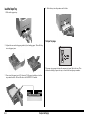
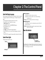
1
OKIDATA
®
OKIPAGE 20 & 20DX
User’s Guide
Every effort has been made to ensure that the information in this document
is complete, accurate, and up-to-date. OKIDATA assumes no responsibility
for the results of errors beyond its control. OKIDATA also cannot guarantee
that changes in software and equipment made by other manufacturers and
referred to in this guide will not affect the applicability of the information
in it. Mention of software products manufactured by other companies does
not necessarily constitute endorsement by OKIDATA.
Copyright 1998 by OKIDATA. All rights reserved.
First edition January, 1998.
Written and produced by the OKIDATA Publications Department. Please
address any comments on this publication
• by mail to:
Publications Department
OKIDATA
532 Fellowship Road
Mount Laurel, New Jersey 08054
• or by email to:
Hewlett-Packard, HP, LaserJet, and PCL5e are registered trademarks of
Hewlett-Packard Company. PostScript and Adobe are trademarks of Adobe
Systems Inc. which may be registered in certain jurisdictions. IBM is a registered trademark of International Business Machines Corp. Epson is a registered
trademark of Epson America, Inc. Microsoft and Windows are either registered
trademarks or trademarks of Microsoft Corporation in the United States and/or
other countries. Intellifont is a registered trademark of Compugraphic Corporation. Zip Code is a registered trademark of the United States Postal Service.
ENERGY STAR is a registered trademark of the United States Environmental
Protection Agency.
Portions of software © 1994-1995 Adobe Systems Incorporated. All Rights
Reserved.
[email protected]
We welcome you to visit our web site:
OKIDATA, OKIPAGE and Oki Smoothing Technology (OST) are registered
trademarks and OKILAN is a trademark of Oki Electric Industry Company,
Ltd. OKIDATA marque déposée de Oki Electric Industry Company, Ltd.;
marca registrada, Oki Electric Industry Company, Ltd.
ENERGY STAR
http://www.okidata.com
As an ENERGY STAR® Partner, OKIDATA has
determined that this product meets the
ENERGY STAR guidelines for energy efficiency.
Contents
Chapter 1: Setting Up ................................. 1
Select a Suitable Location ................................. 1
Unpack ............................................................... 1
Your printer ................................................... 1
The accessories ............................................. 1
Check the contents ............................................. 1
Getting to Know Your Printer ............................ 2
Front View ................................................. 2
Rear View .................................................. 2
Prepare the Image Drum .................................... 3
Install the Toner ................................................. 4
Load Paper ......................................................... 5
Paper Specifications ...................................... 5
Weight ....................................................... 5
Usable Types ............................................. 5
Finish ........................................................ 5
Composition .............................................. 5
Letterhead Stationary/Preprinted Forms ... 5
Paper Feed Paths ........................................... 5
Load the Paper Tray ...................................... 6
The Paper Tray Gauge .............................. 6
Storing Paper ................................................. 7
Select a Paper Exit Path ................................ 7
Top Paper Exit........................................... 8
Rear Paper Exit ......................................... 8
Connect to Your Computer ................................ 9
Parallel Connection ....................................... 9
Attach the Parallel Cable .......................... 9
IEEE 1284 Parallel Interface .................... 9
Bi-Directional Parallel Mode .................... 9
Parallel Interface Pin Assignments ......... 10
Serial Connection: RS232-C ....................... 11
Attach the Serial Cable ........................... 11
RS232-C Serial Interface ........................ 11
Serial Mode ............................................. 11
Serial Interface Pin Assignments ............ 11
Connect to Power ............................................. 12
Check the Menu: Model 20DX Only .............. 12
Print the Demo Page ........................................ 12
Install the Printer Software .............................. 12
Chapter 2: The Control Panel .................. 13
Select the Display Language ........................... 13
Control Panel Lights ........................................ 13
Paper Size Indicator ......................................... 13
Control Panel Button Functions ...................... 14
Button Function Summary .......................... 14
Chapter 3: The Printer Menus ................. 15
Selecting Printer Features Using Your
Software ......................................................... 15
Selecting Printer Features Using Your Printer
Driver ............................................................. 15
Selecting Printer Features Using the Printer
Main Menus................................................... 15
Printing the Main Menus ............................ 15
How to Use the Main Menus ...................... 15
Quick Access Menus............................... 16
Using the Level-1 Menu ......................... 16
Level-1 Menu Settings ............................ 17
Level-1 Menu Selections for IBM PPR III
XL & EPSON FX Emulations .............. 20
Using the Level-2 Menu ......................... 21
Level-2 Menu Settings ............................ 21
The User Maintenance Menu .......................... 24
Summary of Maintenance Menu
Categories: ............................................ 24
Maintenance Menu Settings ................... 24
English–i
Chapter 4: The Front Feeder ................... 27
Chapter 7: Accessories ............................. 41
Using the Front Feeder to Print Multiple Pieces
of Media ........................................................ 28
The Front Feeder: Printing Individual Pieces
(Manual Feed) ............................................... 29
Manual Feed: Standard Paper ..................... 29
Setting up Manual Feed for Standard
Weight Paper ......................................... 29
Manual Feed: Envelopes ............................. 30
Setting up to Print an Envelope .............. 30
Manual Feed: Labels ................................... 31
Setting up to Print Labels ....................... 31
Manual Feed: Transparencies...................... 32
Setting up to Print a Transparency .......... 32
Manual Feed: Heavy (Card) Stock .............. 33
Heavy (Card) Stock Specifications ......... 33
Setting up to Print Heavy Stock .............. 33
Using the Automatic Tray Switch Feature ...... 34
Optional Paper Handling Accessories ............. 41
Multi-Purpose Feeder .................................. 41
Paper Expansion Tray ................................. 41
Duplex Feeder ............................................. 41
Additional Options .......................................... 41
Network Card .............................................. 41
Adobe PostScript Level 2 SIMM Kit .......... 42
Flash ROM Memory SIMMs ...................... 42
Expanded Memory SIMMs ......................... 42
SIMM Configurations ..................................... 42
Chapter 5: Duplex Printing ..................... 35
Portrait Versus Landscape ............................... 35
Duplex Printing: Windows NT 3.51 ................ 35
Duplex Printing: Windows 3.1x ...................... 35
Duplex Printing: Windows 95 ........................ 36
Duplex Printing: Windows NT 4.0 .................. 36
Chapter 6: Fonts ....................................... 37
Available Fonts ................................................ 37
Printing a Sample of Resident Fonts ........... 37
Summary of Available Fonts ....................... 37
Fixed Scalable Fonts ............................... 37
Proportional Scalable Fonts .................... 37
Bitmap Fonts ........................................... 38
IBM/Epson Emulation Fonts .................. 38
Selecting Fonts ................................................ 39
Using Bar Code Fonts ..................................... 39
Symbol Sets ..................................................... 39
Adobe PostScript Fonts Option ....................... 39
E–ii
Chapter 8: Maintenance .......................... 43
General Consumables Information .................. 43
The Toner Cartridge: Type 7 ....................... 43
Toner Cartridge Life ............................... 43
The Image Drum: Type 7 ............................ 43
Image Drum Life .................................... 43
Replacing the Toner Cartridge ......................... 44
Replacing the Image Drum Cartridge ............. 46
Cleaning the LED Array .................................. 48
Generating a Drum Cleaning Page .................. 48
Chapter 9: Problem Solving .................... 49
Paper Jams ....................................................... 49
Paper Jam Messages .................................... 49
Why Paper Jams Occur ................................... 50
Clearing Paper Jams ........................................ 50
Clearing a Paper Input Jam ......................... 50
Clearing a Paper Feed Jam .......................... 51
Clearing a Paper Exit Jam ........................... 52
Clearing Duplex Feeder Paper Jams................ 52
Clearing Duplex Feeder Input Jams ............ 52
Clearing Duplex Feeder Open Jam ............. 52
Clearing Duplex Feeder Jam 1 & 2 ............. 53
Clearing Duplex Feeder Jam 3 .................... 54
Printer Display Messages ................................ 54
Print Quality Problems .................................... 57
Adjusting Print Quality ............................... 60
Software Problems ...................................... 60
Hardware Problems ......................................... 62
Appendix A: Service & Support ............. 63
How to Get Service.......................................... 63
Your Dealer ................................................. 63
Customer Support Center ............................ 63
Customer Service Representatives .............. 63
Faxable Facts ............................................... 63
Internet ........................................................ 64
Okidata Service Centers .............................. 64
Okidata US and Canada Service Center
Locations .............................................. 64
Purchasing Supplies ........................................ 64
Ways to Purchase ........................................ 64
Supply Order Numbers ............................... 64
Toner Cartridge, “Type 7” ....................... 64
Image Drum, “Type 7”............................ 64
Appendix B: Specifications ..................... 65
General Specifications ..................................... 65
Typefaces ......................................................... 65
Paper Handling Specifications ........................ 65
Environmental Specifications .......................... 65
Electrical Specifications .................................. 66
Physical Specifications .................................... 66
Appendix C: Installing SIMMs ................ 67
SIMM Configurations ..................................... 67
Installing SIMMs ............................................. 67
Limited Warranty ...................................... 71
On-Site Repair ................................................. 71
Okidata Service Centers .............................. 72
Material Safety Data Sheet ..................... 73
Index ........................................................... 75
Contents
Important Safety Instructions
Your OKIDATA printer has been carefully designed to give you years of
safe, reliable performance. As with all electrical equipment, however, there
are a few basic precautions you should take to avoid hurting yourself or
damaging the printer:
• Read the setup and operating instructions in this handbook carefully. Be
sure to save it for future reference.
• Read and follow all warning and instruction labels on the printer itself.
• Unplug the printer before you clean it. Use only a damp cloth; do not
use liquid or aerosol cleaners.
• Place your printer on a firm, solid surface. If you put it on something
unsteady, it may fall and be damaged; if you place it on a soft surface,
such as a rug, sofa, or cushioned surface, the vents may be blocked,
causing the printer to overheat.
• To protect your printer from overheating, make sure all openings on the
printer are not blocked. Don’t put the printer on or near a heat source,
such as a radiator or heat register. If you put it in any kind of enclosure,
make sure it is well ventilated.
• Do not use your printer near water, or spill liquid of any kind into it. Be
certain that your power source matches the rating listed on the back of
the printer. If you’re not sure, check with your dealer or with your local
power company.
• Your printer has a grounded, 3-prong plug as a safety feature, and it will
only fit into a grounded outlet. If you can’t plug it in, chances are you
have an older, non-grounded outlet; contact an electrician to have the
outlet replaced. Do not use an adapter to defeat the grounding.
• The printer must be installed near a power outlet which remains easily
accessible.
• To avoid damaging the power cord, don’t put anything on it or place it
where it will be walked on. If the cord becomes damaged or frayed,
replace it immediately.
• If you’re using an extension cord or power strip with the printer, make
sure that the total of the amperes required by all the equipment on the
extension is less than the extension’s rating. The total ratings of all
equipment plugged into the outlet should not exceed 15 amperes.
• Do not poke anything into the ventilation slots on the printer; you could
get an electrical shock or cause hazardous electrical arcing.
• Aside from the routine maintenance described in this handbook, don’t try
to service the printer yourself; opening the cover may expose you to
shocks or other hazards. Don’t make any adjustments other than those
outlined in the handbook—you may cause damage requiring extensive
repair work. Appendix A, Support, Service, and Warranty Information,
explains how to get your printer serviced by qualified OKIDATA technicians.
• If anything happens that indicates that your printer is not working
properly or has been damaged, unplug it immediately and follow the
procedures in Appendix A for having your printer serviced. These are
some of the things to look for:
- The power cord or plug is frayed or damaged.
- Liquid has been spilled into the printer, or it has been exposed to
water.
- The printer has been dropped, or the cabinet is damaged.
- The printer doesn’t function normally when you’re following the
operating instructions.
English–iii
Warranty Enhancement Programs
• Available in the U.S. and Canada only
For more information . . .
OKI Extend™
For pricing and more detailed information on these programs:
This program offers you the
opportunity to purchase an
extension of the standard
warranty for your Okidata
printer. You can add 1 or 2 years
to the standard warranty.
OKI On-Site™
If you experience a malfunction
of your Okidata printer and the
problem can not be resolved
over the phone, this program
offers you repair of your printer
right at your place of business,
by our national service provider.
iv–English
• call 1-800-OKIDATA (1-800-654-3282)
or
• visit our Web site: http://www.okidata.com
FCC/IC/CE Statements
Federal Communications Commission
Radio Frequency Interference Statement
for 120-Volt Models
WARNING: This equipment has been tested and found to comply with the
limits for a Class B digital device, pursuant to Part 15 of the FCC rules.
These limits are designed to provide reasonable protection against harmful
interference in a residential installation. This equipment generates, uses and
can radiate radio frequency energy and, if not installed and used in accordance with the instructions, may cause harmful interference to radio
communications. However, there is no guarantee that interference will not
occur in a particular installation. If this equipment does cause harmful
interference to radio or television reception, which can be determined by
turning the equipment off and on, the user is encouraged to try to correct
the interference by one or more of the following measures:
Industry Canada Radio Interference Statement
for 120-Volt Models
This OKIDATA apparatus complies with the Class B limits for radio
interference as specified in the Industry Canada Radio Interference Regulations.
• Reorient or relocate the receiving antenna.
• Increase the separation between the equipment and the receiver.
• Plug the unit into an outlet on a circuit different from that to which the
receiver is connected.
• Consult the dealer or an experienced radio/television technician for help.
✔ It is the responsibility of the user to obtain the required shielded cable in
order to ensure compliance of this equipment with FCC regulations.
Changes or modifications not expressly approved by OKIDATA may void
your authority to operate this device.
English–v
Federal Communications Commission
Radio Frequency Interference Statement
for 230/240-Volt Models
WARNING: This equipment has been tested and found to comply with the
limits for a Class A digital device, pursuant to Part 15 of the FCC Rules.
These limits are designed to provide reasonable protection against harmful
interference when the equipment is operated in a commercial environment.
This equipment generates, uses and can radiate radio frequency energy and,
if not installed and used in accordance with the instructions, may cause
harmful interference to radio communications. Operation of this equipment
in a residential area is likely to cause harmful interference in which case the
user will be required to correct the interference at his own expense.
European Union Council of the
European Communities Statements
of Electromagnetic Conformance for
230/240-Volt Models
This product complies with the requirements of the Council Directive 89/
336/EEC on the approximation of the laws of the member states relating to
electromagnetic compatibility.
This product is in conformity with Directive 73/23/EEC on the harmonization of the laws of Member States relating to electrical equipment designed
for use within certain voltage limits.
✔ It is the responsibility of the user to obtain the required shielded cable in
order to ensure compliance of this equipment with FCC regulations.
Changes or modifications not expressly approved by OKIDATA may void
your authority to operate this device.
Industry Canada Radio Interference Statement
for 230/240-Volt Models
This OKIDATA apparatus complies with the Class A limits for radio
interference as specified in the Industry Canada Radio Interference Regulations.
E–vi
FCC/IC/CE
Chapter 1: Setting Up
This chapter explains how to unpack and install your printer.
The accessories
Select a Suitable Location
As you unpack the accessories, please save the packing material in the event
you need to repack the printer for shipping.
Before unpacking your printer, select a suitable location for it which meets
the following criteria:
Important! Be sure to store the black light-shield bag near the printer to
protect the image drum in case you need to take it out of
the printer for more than a minute or so. This bag is also
used to store the image drum in case you need to ship the
printer.
• A firm, level surface, such as a table or desktop
• Clearance to open the cover, the paper tray, and the rear paper exit
extender
• Air circulation around the printer to prevent overheating (recommended
minimum of 4" in all directions)
• A nearby power source
• Room temperature of 50° to 90°F (10° to 32°C)
• Relative humidity of 20-80%
• No direct sunlight
Unpack
Your printer
1. Unpack the printer and place it on the surface you’ve selected.
2. Remove the printer from the plastic bag.
3. Lift up the corner of the protective film and peel it off the control panel.
Check the contents
➊ OKIPAGE 20 Printer
➋ Toner Cartridge with LED lens
cleaners
➌ Power Cord
➍ Software Support CD
➎ Software Support
Diskette
➋
➏ Light-shield bag
If you are missing
anything, contact your
dealer.
You will need to purchase:
➊
➌
➏
➍
➎
• Paper (see page 5)
• Interface cable: either bi-directional IEEE-1284 parallel cable (see page
9) or RS232-C serial cable (see page 11)
English–1
Getting to Know Your Printer
Printer Cover
Top Exit Path
Rear Paper Exit
Display
Power Cord Socket
Control Panel
IEEE 1284
Parallel Interface
Front Feeder
On/Off Switch
OPEN Button
OKIPAGE 20:
RS232-C Serial Interface
Paper Gauge
Paper Tray
Removable Plate for
installing optional
Duplex Feeder
OKIPAGE 20DX: Duplex Feeder
Front View
E–2
Rear View
Chapter 1: Setting Up
4. Remove the tape and shipping insert from the image drum and discard
them.
Prepare the Image Drum
1. Press the OPEN button.
2. Lift the cover (the cover must be lifted completely to remove the image
drum cartridge).
5. Reinstall the image drum in the printer, placing the alignment pins on
each side of the drum into the slots in the printer.
Pin
Caution!Be careful not to touch the image drum’s shiny green surface!
Slot
3. Lift out the image drum and remove the protective paper.
Chapter 1: Setting Up
E–3
4. Lower the right side of the toner cartridge, aligning the slot in the cartridge with the ridge in the image drum.
Install the Toner
1. Remove the toner cartridge from the foil package and shake it from side
to side a few times to distribute the toner evenly.
Slot
5. Push the gray lock lever toward the back of the printer until it stops.
2. Carefully peel off the tape from the bottom of the cartridge.
3. Place the left end of the toner cartridge into the toner well, inserting the
recess in the end of the toner cartridge over the tab on the image drum.
6. Close the printer cover.
Recess
Tab
Note: If you get toner on your clothing, brush it off with a dry cloth. Wash
clothing in cold water; hot water sets toner.
E–4
Chapter 1: Setting Up
Paper Feed Paths
Load Paper
Paper can be supplied to the printer in four ways:
Paper Specifications
When you buy paper, keep in mind that page printers require a smooth
finish paper. For most everyday applications, paper rated for copiers and
laser printers should work well with your printer. Before buying any large
quantity of a particular paper, always test a sample first.
Weight
•
•
•
•
•
Main Tray: 16 - 28 lb.
Optional Paper Expansion Tray: 16-28 lb.
Front Feeder: 16 – 36 lb.
Optional Multipurpose Feeder: 16-24 lb.
Duplex Feeder (OKIPAGE 20DX): 16-24 lb. (option for OKIPAGE 20)
• From the paper tray which
holds up to 530 sheets of
20-lb. paper
• From the 100-sheet Front
Feeder (see Chapter 4)
• From the optional
100-sheet/50 envelope
multipurpose feeder (see
Chapter 7)
Usable Types
• Bond
• Smooth, low moisture paper rated for copier and laser printers
• Cover stock; heavy bond (36 lb. max.): Manual feed only
Finish
• Smooth, non-textured
• Copier-type paper or paper with a Sheffield rating of 100 to 250
• From the optional paper
expansion tray which holds
up to 530 sheets of 20-lb.
paper (see Chapter 7)
Composition
• 100% wood pulp or low cotton content
Note: Most papers have some cotton or rag content. Avoid papers with a
high cotton or rag content.
Letterhead Stationery/Preprinted Forms
• Ink must withstand 392°F (200°C) for 0.1 second.
The paper tray will accommodate 16 to 28 lb. paper within the following
size ranges:
• Width: 3.4 to 8.5 inches (86.4 to 216 mm)
• Length: 5.5 to 14 inches (140 to 355.6 mm)
Chapter 1: Setting Up
E–5
4. Push the tray into the printer until it locks.
Load the Paper Tray
1. Pull out the paper tray.
The Paper Tray Gauge
2. Adjust the rear and side paper guides before loading paper. This will help
to avoid paper jams.
The paper tray gauge indicates the amount of paper left in the tray. This
eliminates having to open the tray to check how much paper remains.
3. Fan a stack of paper (up to 530 sheets of 20 lb. paper) and place it in the
tray under the tabs. Do not fill above the PAPER FULL marks.
E–6
Chapter 1: Setting Up
Storing Paper
Select a Paper Exit Path
If paper is stored improperly, print quality could be affected.
The OKIPAGE 20 has two paper paths:
•
•
•
•
•
• Top Exit: the normal exit used for routine printing
Store paper in a dark, dry place such as a closet or a cabinet
Don’t open the package until you are ready to use it
Always store paper lying flat or it may curl
Store your paper in a static-free environment
Ideally, store paper at a constant temperature of 70°F (21.1°C) with less
than 50% humidity.
• Discard the top sheet from each ream of paper before loading it into the
paper tray — it may be contaminated with glue or dust.
• Rear Exit: used for special types of print media such as envelopes,
labels, transparencies, etc.
Chapter 1: Setting Up
E–7
Top Paper Exit
Rear Paper Exit
The top paper exit is the one normally used for routine printing.
Use rear exit when printing on heavy paper, envelopes, labels, and transparencies.
•
•
•
•
Printed pages feed face down into the bin on top of the printer
Bin holds 250 sheets of 20 lb. paper
Pages stack in the correct order
When the bin is full, STACKER FULL REMOVE THE PAPER displays
in the control panel window and printing will stop until the paper is
removed
•
•
•
•
Printed pages feed face up into the rear tray
Tray holds a maximum of 100 sheets of 20 lb. paper or 10 envelopes
Pages stack in reverse order
To avoid paper jams, remove paper when rear exit tray is full.
To use rear paper exit:
To use the top paper exit:
1. Lift out the paper catcher and pull it toward the front of the printer until it
stops.
Caution! Do not extend the rear exit tray while printing: a paper jam may
occur!
1. Pull the tray down.
2. Flip up the extender.
2. Pivot out the extenders.
E–8
Chapter 1: Setting Up
IEEE 1284 Parallel Interface
Connect to Your Computer
Parallel cable requirements:
Parallel Connection
Attach the Parallel Cable
We recommend that you use a bi-directional parallel printer cable. For best
results, purchase a cable marked “IEEE 1284-compliant.”
Important! To comply with FCC regulations, the cable must be
shielded and UL and CSA approved.
Note: OKIDATA has tested and approved the following bi-directional cable:
Part Number 70000803. See Appendix A for purchasing information.
• Cable must be shielded with twisted pair conductors, and must be UL
and CSA approved
• Maximum length for bi-directional cable is 6 feet (1.8 meters). For
lengths greater than 6 feet, use a cable marked IEEE 1284-compliant.
• Printer connector is an IEEE 1284-B receptacle (36 pins, 0.085” center
line)
• Port supports bi-directional IEEE 1284 communications (compatibility,
nibble, and ECP modes)
Bi-Directional Parallel Mode
If you are using the Status Monitor software, which provides on-line
feedback of the printer status, BI-DIRECTION must be set to ENABLE
(default) in the Level-2 printer main menu (see Chapter 3).
To connect the printer to your computer:
1. Turn both your printer and computer OFF.
The recommended cable length for bi-directional communications is 6 ft.
(1.8 meters). The standard parallel cables available at computer stores
should work fine. For extended distances, higher quality IEEE 1284-compliant cables are available.
2. Insert the wide connector on the cable into the parallel port on your
printer. Make sure the connector is fully inserted, then snap both wire
clips into the notches on the cable connector.
3. Insert the other end of the cable into the parallel port on your computer
and tighten the screws.
Caution!Be sure not to over tighten the screws — this could damage
the screw posts on your computer!
Chapter 1: Setting Up
E–9
Parallel Interface Pin Assignments
E–10
Pin No.
Signal Name
Signal Dire ction
Compatible
Nibble
ECP
Functions
1
Data Strobe
To printer
nStrobe
Host Clk
Host Clk
Parallel data sampling strobe
2- 8
Data Bit n
To printer
Data n (LSB)
Data n (LSB)
Data n (LSB)
Parallel input data
9
Data Bit 8
To printer
Data 8 (MSB)
Data 8 (MSB)
Data 8 (MSB)
Parallel input data
10
Acknowledge
From printer
nAck
PtrClk
PeriphClk
Completion of data input or end of
functioning
11
Busy
From printer
Busy
PtrBusy
PeriphAck
During print processing or during alarm
12
Paper End
From printer
PError
AckDataReq
nAckReverse
End of paper
13
Select
From printer
Select
Xflag
Xflag
Select state (on- line)
14
Auto Feed
To printer
nAutoFd
HostBusy
HostAck
Request to change mode
15
-
-
-
-
-
(not used)
16
0V
-
Logic Gnd
Logic Gnd
Logic Gnd
Signal ground
17
Chassis Ground
-
Chassis Gnd
Chassis Gnd
Chassis Gnd
Chassis ground
18
+5V
From printer
Peripheral Logic High
Peripheral Logic High
Peripheral Logic High
50 mA max.
19
0V
-
Signal Ground (nStrobe)
Signal Ground (nStrobe)
Signal Ground (nStrobe)
Signal ground
20 to 27
0V
-
Signal Ground (Data 1- 8)
(Data 1- 8)
(Data 1- 8)
Signal ground
28
0V
-
Signal Ground (PError,
Select, nAck)
Signal Ground (PError,
Select, nAck)
Signal Ground (PError,
Select, nAck)
Signal ground
29
0V
-
Signal Ground (Busy, nFault)
Signal Ground (Busy, nFault)
Signal Ground (Busy, nFault)
Signal ground
30
0V
-
Signal Ground (nAutoFd,
nSelectln, nlnit)
Signal Ground (nAutoFd,
nSelectln, nlnit)
Signal Ground (nAutoFd,
nSelectln, nlnit)
Signal ground
31
Input PRIME
To printer
nlnit
nlnit
nReverseReq
Initializing signal
32
Fault
From printer
nFault
nDataAvail
nPerophReq
Paper out or during alarm
33
0V
-
-
-
-
Signal ground
34
-
-
-
-
-
-
35
-
From printer
-
-
-
Fix at Logic "1"
36
Select In
To printer
nSelectIn
1284 Active
1284 Active
Request to change Mode
Chapter 1: Setting Up
Serial Mode
Serial Connection: RS232-C
The serial interface settings on your printer and computer must match. To
change printer settings, enter the Level 2 menu (press ON-LINE to place the
printer off-line, then press MENU 1/Menu 2 for 2 seconds, until PRINT
MODE appears) and select the RS232C SERIAL category. Set FLOW CONTROL, BAUD RATE, DATA BITS, PARITY, and MIN. BUSY to match the settings
on your computer. Following are the printer default settings for these
parameters:
Attach the Serial Cable
To connect the printer to your computer:
1. Turn both your printer and computer OFF.
2. Insert the male connector on the cable into the serial port on your printer.
Make sure the connector is fully inserted, then tighten the screws.
FLOW CONTROL
BAUD RATE
DATA BITS
PARITY
MIN. BUSY
DTR HI POLARITY
9600 BAUD
8 BITS
NONE
200 mSECONDS
Serial Interface Pin Assignments
3. Insert the other end of the cable into the serial port on your computer and
tighten the screws.
Caution!Be sure not to over tighten the screws — this could damage
the screw posts!
RS232-C Serial Interface
Serial cable requirements:
• Cable must be shielded with twisted pair conductors, and must be UL
and CSA approved
• Maximum length for serial cable is 6 feet (1.8 meters).
• Printer connector is Type 17LE-13250-27 (D4CC) receptacle (25 pins)
Chapter 1: Setting Up
Pin
Signal
Symbol
Dire ction
1
Frame Ground
FG
-
2
Transmitted Data
TD
To printer
3
Received Data
RD
To printer
4
Request to Send
RTS
From printer
5- 6
-
-
-
7
Signal Ground
SG
-
8- 17
-
-
-
18
+5V (50 ma max.)
-
From printer
19
-
-
-
20
Data Terminal Ready
DTR
From printer
21- 25
-
-
-
E–11
Connect to Power
1. Plug the female end of the power cord supplied with the printer into the
power socket on the back of the printer.
4. Press MENU1/Menu 2 twice.
DUPLEX PRINTING displays.
5. Make sure the second line of the display reads ON *. If not, press the
ENTER button, then ©/Reset, then ENTER.
ON * displays.
6. Press ON LINE to exit the menu.
Print the Demo Page
2. Plug the other end of the cable into a suitable grounded power outlet or
power strip.
Caution!If you are using a power strip, be sure the total amperage rating
of the strip does not exceed the total amperage of the equipment
plugged into it.
1. Turn the printer ON.
INITIALIZING displays briefly in the control panel window, then ON-LINE
displays.
2. Press ON-LINE to place the printer off-line.
3. Press FORM FEED/Print Demo for 2 seconds (until the display reads
PRINT DEMO PAGE).
4. To print the Demo Page for the HP® PCL6 emulation, press ENTER/
Power Save. To print the Demo Page for the IBM® or Epson® emulation,
press ©/Reset until the emulation you want appears on the second line of
the display, then press ENTER/Power Save.
The Demo page prints.
Install the Printer Software
Check the Menu: Model 20DX Only
Check the menu to be sure that the Duplex printing feature is turned on:
1. Turn the printer ON.
INITIALIZING displays briefly in the control panel window, then ON-LINE
displays.
2. Press ON-LINE to place the printer off-line.
3. Press MENU1/Menu 2.
PERSONALITY displays.
E–12
You are now ready to install the printer software. See the separate booklet
“Software Install Guide” for information on printer drivers and instructions
on loading the printer software.
Chapter 1: Setting Up
Chapter 2: The Control Panel
Select the Display Language
Printer messages can be displayed in the control panel window in a number
of languages. English is the default language. To change the display language:
1. Press ON-LINE to change the printer status to off-line.
2. Press MENU 1/Menu 2 and hold for 2 seconds.
PRINT MODE displays.
3. Press MENU 1/Menu 2 until LANGUAGE displays.
4. Press ENTER/Power Save.
ENGLISH displays.
5. Press ©/Reset until the desired language displays.
6. Press ENTER/Power Save to select the new language as the default
setting.
7. Press ON-LINE to engage the change and place the printer back on-line.
READY Light (Amber)
On: Printer is on-line, ready to receive data
Off: Printer is off-line, unable to receive data; initializing;
warming up; error
Blinking: Printer is printing a menu, fonts, or demo page
ATTENTION Light (Red)
On: Warning—toner is low, change drum, near end of fuser life
Off: Normal state
Blinking: Operator assistance required—paper jam, paper out, paper
request, service required
Paper Size Indicator
Control Panel Lights
The lights indicate the printer status:
READY Light
Paper Size Indicator
[set for LETTER, the default]
The flashing marker in the printer display window indicates the paper size
installed in the paper tray. This feature eliminates having to open the paper
tray to see which paper size is loaded.
ATTENTION Light
English–13
Control Panel Button Functions
Press: In Menu Mode advances to the next item. Also used with
§/Recover to generate a drum cleaning page: see “Generating a
Drum Cleaning Page” in Chapter 8.
Press/hold: Deletes data in buffer and executes internal reset.
To access printer functions from the control panel, place the printer off-line
(press the ON-LINE button: OFF-LINE appears on the display).
• To access the top function of each button, press the button briefly.
• To access the bottom function, press and hold the button for 2 to 3
seconds.
Button Function Summary
Press: In Menu Mode: sets displayed Menu item as the user default.
Press/hold: Enters the Power Save quick menu.
Press: Changes printer status from receive data mode (on-line) to local
function mode (off-line).
Press: Enters Level-1 menu. Once in the Level-1 menu, press this
button to move to the next menu item, or press and hold to cycle
backwards through all the Level-1 menu categories.
Press: Enters the Paper Size Quick Menu.
Press/hold: Prints a listing of the current and default menu settings (HP
PCL 6, IBM Proprinter III XL, or Epson FX).
Press/hold: Enters Level-2 menu.
Press: In Menu Mode returns to previous item; press and hold to cycle
backwards through all the items within a category. Also used
with ©/Reset to generate a drum cleaning page: see “Generating
a Drum Cleaning Page” in Chapter 8.
Press: Enters the Tray Select Quick Menu.
Press/hold: Prints a sample of installed printer fonts (HP PCL 6, IBM
Proprinter III XL, or Epson FX).
Press/hold: Clears error condition and returns printer on-line.
Press: Ejects the current page. Any data held in the buffer is printed.
Press/hold: Prints a Demo Page (HP PCL 6, IBM Proprinter III XL, or
Epson FX).
E–14
Chapter 2: The Control Panel
Chapter 3: The Printer Menus
Most printer features are selected directly from your software application. If
you want to use the printer’s Menu to select features, see Chapter 3. Remember, features selected in your software will override features selected in
the printer’s Menu.
Selecting Printer Features Using Your Software
Most printer features like font, paper size, and page orientation can be set in
your software program. This is the easiest way to control your printer.
Check your software documentation for information.
Selecting Printer Features Using Your Printer
Driver
Printing the Main Menus
To print a list of the menu items and settings currently engaged:
1. Place the printer off-line (press ON LINE).
2. Press and hold PAPER SIZE/Print Menu until the display reads PRINT
MENU.
3. To print the menu for the HP PCL6 emulation, press ENTER/Power
Save. To print the menu for the IBM or Epson emulation, press ©/Reset
until the emulation you want appears on the second line of the display,
then press ENTER/Power Save.
4. The menu prints.
The printout shows the factory default settings, the current user settings, and
the amount of memory installed in your printer.
Printer features can also be set using the Status Monitor software included
with your printer. However, these settings will be overridden by any settings
made within your software package.
How to Use the Main Menus
Selecting Printer Features Using the Printer
Main Menus
• accessed using control panel buttons
• displayed in the control panel window
• organized by Categories → Items → Selections
You can also select printer features in the printer main menus by using the
control panel. However, features set in your software program will override
the same features selected in the printer main menu.
There are two levels within the main printer menu: Level-1 and Level-2. To
access the menus, place the printer off-line (press ON LINE), then
Important! Use the printer main menu only when your software does
not let you select features or when you are setting printer
features that your software does not control.
Main menu features are
• to access the Level-1 menu, press MENU 1/Menu 2 (the display will read
PERSONALITY).
• to access the Level-2 menu, press and hold the MENU 1/ Menu 2 button
until the display reads PRINT MODE).
English–15
Quick Access Menus
The PAPER SIZE, TRAY TYPE, and POWER SAVE menu features can be
accessed directly without having to step through the main menu.
To do this:
1. Place the printer off-line (press ON LINE).
2. Press and release PAPER SIZE, or
Press and release TRAY TYPE, or
Press POWER SAVE for two full seconds.
3. Press © repeatedly until you see the selection you want.
4. Press ENTER/Power Save to set the selection as the default.
An asterisk (*) appears to indicate the new default setting.
5. Press ON LINE to exit the menu and place the printer back on-line.
Using the Level-1 Menu
1. Press ON-LINE to place the printer off-line.
2. Press MENU 1/Menu 2 to enter the Level-1 menu.
3. Continue to press MENU 1/Menu 2 repeatedly to advance through the
Level-1 menu categories.
3. Press ENTER/Power Save to select a category.
The current default setting displays.
Note: Some categories include more than one item. In such categories,
after you press ENTER, press MENU 1/Menu 2 to advance to the
next item before proceeding to step 4.
4. Press © repeatedly to display the selections. Stop when you see the
selection you want.
5. Press ENTER/Power Save to set a selection as the default.
An asterisk (*) appears to indicate the new default setting.
6. Repeat steps 3 through 5 until you have made all the menu changes you
wish to make, then press ON LINE to exit the Menu Mode and place the
printer back on-line.
E–16
Notes:
• If the MENU 1/Menu 2 button is pressed and held while in Menu Mode,
the printer cycles through the categories in reverse order.
• If you enter the Level-1 menu and make a selection while there is data
present in the buffer, or while a DLL/Macro is present, the RESET TO
SAVE message appears on the display. When you press the ©/Reset
button, all data in the buffer and any temporary soft fonts or macros will
be cleared.
Example:
If you have one of the optional paper expansion trays installed
and you want to set the printer to automatically switch to
another tray with the same size paper when the first tray runs
out of paper:
1. Press ON LINE.
2. Press MENU 1/Menu 2 to enter the Menu Mode.
3. Press MENU 1/Menu 2 again to move to the
TRAY SELECT category.
4. Press ENTER.
5. Press MENU 1/Menu 2 twice to move to the AUTO TRAY
SWITCH item.
6. Press once to get to the ON selection.
7. Press ENTER to engage the ON selection (an asterisk will
appear next to ON).
8. Press ON LINE to exit the Menu Mode.
Chapter 3: The Printer Menus
Level-1 Menu Settings
Summary of Level-1 Categories:
•
•
•
•
•
•
•
•
•
•
•
•
PERSONALITY
TRAY SELECT
DUPLEX PRINTING
EDIT SIZE
PAPER SIZE
MEDIA TYPE
PAPER SIZE CHECK
COPIES
FONTS & SYMBOLS
PAGE LAYOUT1
PAGE LAYOUT2
HOST INTERFACE
Level-1 Menu Categories (e.g., PERSONALITY),
Items (e.g., EMULATION) and Selections (e.g., HP
LaserJet 5, IBM PPR II XL, Epson FX) are summarized below: default Selections are in italic (e.g.,
AUTO Emulation).
PERSONALITY
EMULATION
AUTO Emulation
HP LaserJet 5
IBM PPR III XL
Epson FX
Adobe® PostScript® (appears only if PostScript
selection is installed)
Notes: Auto Emulation automatically
switches between HP LaserJet 5, IBM
PPR III XL and Epson FX emulations.
TRAY SELECT
MANUAL FEED
OFF
ON
Notes: Selects Manual Feed mode: paper is
fed from the Manual Feeder regardless
of the PAPER FEED setting. When the
job is ready to print, MANUAL
REQUEST will appear on the display;
be sure to place paper on Manual
Feeder, then press FORM FEED
button to start printing.
PAPER FEED
TRAY 1
TRAY 2*
TRAY 3*
FRONT TRAY (Manual Feeder)
MULTI FEEDER*
Notes: * Selection only appears if appropriate
optional accessory is installed.
Select paper source.
AUTO TRAY SWITCH
OFF
ON
Notes: ON = When paper tray, printer
automatically switches to the optional
Paper Expansion Tray, if installed, then
to the Manual Feeder, then to the
optional Multi-Purpose feeder, if
installed.
DUPLEX PRINTING (appears in OKIPAGE 20 menu
only if Duplex Feeder is installed.)
DUPLEX
ON
OFF
DUPLEX PRINTING (continued)
BIND
LONG EDGE
SHORT EDGE
Notes: Select the orientation for duplex
printing so that the front and back of
printing is properly aligned for the
selected orientation of the pages
(Duplex Printing must be set to ON).
Long Edge sets the orientation for
portrait printing. Short Edge sets the
orientation for landscape printing.
EDIT SIZE
CASSETTE SIZE
LETTER
EXECUTIVE
LEGAL 14
LEGAL13
A4 SIZE
A5 SIZE
A6 SIZE
B5 SIZE
COM-9
COM-10
MONARCH
DL ENVELOPE
C5 ENVELOPE
C4 ENVELOPE
Notes: HP PCL6 mode: Sets the paper size
when the software does not. With the
default Cassette Size selected, the
paper size will be whatever is detected
in the paper tray. If manual feed is
being used, the paper size will be the
one selected in the Level-1 menu
(default is letter).
PostScript mode: Ignored.
Notes: Selects duplex printing (for OKIPAGE
20, optional Duplex Feeder must be
installed).
Chapter 3: The Printer Menus
E–17
Level-1 Menu Settings (continued)
PAPER SIZE
FRONT/MANUAL
LETTER
EXECUTIVE
LEGAL 14
LEGAL13
A4 SIZE
A5 SIZE
A6 SIZE
B5 SIZE
COM-9
COM-10
MONARCH
DL ENVELOPE
C5 ENVELOPE
C4 ENVELOPE
Notes: Select paper size installed in Manual
Feeder. If paper size installed does not
match setting, printer will display
message requesting the size set in
menu.
MULTI FEEDER (appears if option is installed)
LETTER
EXECUTIVE
LEGAL14
LEGAL13
A4 SIZE
A5 SIZE
A6 SIZE
B5 SIZE
COM-9
COM-10
MONARCH
DL ENVELOPE
C5 ENVELOPE
Notes: Appears only if the optional
Multi-Purpose Feeder is installed.
E–18
MEDIA TYPE
TRAY 1
LIGHT
MEDIUM LIGHT
MEDIUM
MEDIUM HEAVY
HEAVY
Notes: Improves print quality and toner
fusing.
Light = 16 lb (60 g/m2)
Medium Light = 18 lb (68 g/m2)
Medium = 20 lb (75 g/m2)
Medium Heavy = 24 lb (90 g/m2)
Heavy = 28 lb (105 g/m2)
TRAY 2 (appears if option is installed))
LIGHT
MEDIUM LIGHT
MEDIUM
MEDIUM HEAVY
HEAVY
Notes: Improves print quality and toner
fusing. Only appears in the menu when
the optional Paper Expansion Tray is
installed.
Light to Heavy weight values are same
as specified for Tray 1.
TRAY 3 (appears if option is installed))
LIGHT
MEDIUM LIGHT
MEDIUM
MEDIUM HEAVY
HEAVY
Notes: Improves print quality and toner
fusing. Only appears in the menu when
two optional Paper Expansion Trays
are installed.
Light to Heavy weight values are same
as specified for Tray 1.
Chapter 3: The Printer Menus
MEDIA TYPE (continued)
FRONT/MANUAL
LIGHT
MEDIUM LIGHT
MEDIUM*
MEDIUM HEAVY
HEAVY
TRANSPARENCY
Notes: Specify print media weight/type to
improve print quality and toner fusing.
Light to Heavy weight values are same
as specified for Tray 1.
MULTI FEEDER (appears if option is installed))
LIGHT
MEDIUM LIGHT
MEDIUM*
MEDIUM HEAVY
HEAVY
TRANSPARENCY
Notes: Specify print media weight/type to
improve print quality and toner fusing.
Light to Heavy weight values are same
as specified for Tray 1.
PAPER SIZE CHECK
ENABLE
DISABLE
Notes: ENABLE = printer only accepts paper
size selected in software which
matches size of paper actually loaded
in tray.
DISABLE = printer will accept any
paper size selected in software.
COPIES
1 to 999
Notes: Select number of copies to print for
each document.
FONTS & SYMBOLS
FONT SOURCE
RESIDENT
SIMM
DOWNLOAD
Notes: Select font source.
SIMM appears only if optional Flash
ROM SIMM is installed.
DOWNLOAD appears if a soft font is
loaded.
FONT NO.
I000 to I0xx
C000
S001
Notes: xx = font ID number (see font print
sample).
Prefix indicates font source:
I = internal (resident) — I000 =
Courier;
C = Card Font (appears only if
optional Flash ROM SIMM is installed)
S = downloaded soft font (appears only
if soft font is loaded)
FONT HEIGHT
10.00 CPI
Range: 0.44 to 99.99 CPI
Notes: Appears if scalable, fixed Courier or
Letter Gothic font is selected.
CPI = characters per inch, settable in
0.01-cpi (press ©/Reset) or 0.1-cpi
(press/hold ©/Reset) increments.
FONTS & SYMBOLS (continued)
FONT HEIGHT
12.00 POINT
4.00 to 999.75 points
Notes: Appears if font selected is proportional/scalable (e.g., CG Times, CG
Omega, Univers, etc.).
Sets character height in points in
0.25-point (press ©/Reset) or 1-point
(press/hold ©/Reset) increments.
72 points = 1 inch
SYMBOL SET (HP PCL6 emulation)
PC-8, ROMAN-8, ISO L1, PC-8 Dan/Nor,
PC-850, Legal, ISO-2 IRV, ISO-4 UK, ISO-6
ASC, ISO-10 S/F, ISO-11 SWE, ISO-14, JASC,
ISO-15 Ita, ISO-16 Por, ISO-17 Spa, ISO-21
Ger, ISO-25 Fre, ISO-57 Chi, ISO-60 Nor,
ISO-61 Nor, ISP-69 Fre, ISO-84 Por, ISO-85
Spa, German, Spanish, ISO Dutch, Roman Ext,
ISO Swedish1, ISO Swedish2, ISO Swedish3,
IBM-437, IBM-850, IBM-860, IBM-863,
IBM-865, PC Set1, PC Ext US, PC Ext D/N, PC
Set2 US, PC Set2 D/N, UN Math, UN Int’l, UN
US, PS Math, PS Text, Math-8, Pi Font, MS
Publish, Win 3.0, DeskTop, Win 3.1 L1, MC
Text, PC-852, Win 3.1 L5, Win 3.1 L2, CWI
Hung, PC-857 TK, ISO L2, ISO L5, PC-8 TK,
Kamenicky, Hebrew NC, Hebrew OC, Plska
Mazvia, ISO L6, Win 3.1 Cyr, PC-866, Win 3.1
Grk, PC-869, PC-855, Greek-437, Greek-437
Cy, Greek-928, Win 3.1 Heb, Serbo Croat2,
Ukrainian, Bulgarian PC-1004, WIN BALTIC,
PC-775, Serbo Croat1, HP ZIP, USPSZIP,
USPSFIM, USPSSTP, Wingdings, Symbol,
OCR-A, OCR-B
PAGE LAYOUT1
A4 PRINT WIDTH
78 COLUMN
80 COLUMN
Notes: HP Mode only. When using A4 size
paper, select 78 columns or condense
to 80 columns so characters will fit on
a line.
WHITE PAGE SKIP
OFF
ON
Notes: HP Mode only. ON = printer will
ignore FF code when buffer is empty.
(Cancels printing a blank page at the
end of a print job.)
CR FUNCTION
CR
CR + LF
Notes: HP Mode only. CR + LF = add LF
command to each CR command.
LF FUNCTION
LF
LF + CR
Notes: HP Mode only. LF+CR= add CR
command to each LF command.
PAGE LAYOUT2
ORIENTATION
PORTRAIT
LANDSCAPE
Notes: Sets printing oriented with the width of
the page (Portrait) or with the length of
the page (landscape).
LINES PER PAGE
60 LINES
5 TO 128 LINES
Notes: Select lines per page in 1 line increments.
Chapter 3: The Printer Menus
E–19
Level-1 Menu Settings (continued)
HOST INTERFACE
PARALLEL
ENABLE
DISABLE
Notes: Enables parallel interface.
RS232C
ENABLE
DISABLE
Notes: Enables serial interface.
OKI HSP
ENABLE
DISABLE
Notes: Enables network interface.
Level-1 Menu Selections for IBM PPR III XL &
EPSON FX Emulations
Default settings below are in italic.
FONTS & SYMBOLS
FONTS & SYMBOLS (continued)
CHARACTER SET
SET 2
SET 1
Notes: Choose Character Set: Standard IBM
Set 1 or Line Graphics IBM Set II
SYMBOL SET
IBM 437, IBM 850, IBM 860, IBM 863, IBM 865,
PC Set1, PC Ext US, PC Ext D/N, PC Set2 US,
PC Set2 D/N, Roman-8, ISO L1, PC-8,
PC-Dan/Nor, PC-850, Legal, ISO-2 IRV, ISO-4
UK, ISO-6 ASC, ISO-10 S/F, ISO-11 Swe,
ISO-14 JASC, ISO-15 Ita, ISO-16 Por, ISO-17
Spa, ISO-21 Ger, ISO-25 Fre, ISO-57 Chi,
ISO-60 Nor, ISO-61 Nor, ISO-69 Fre, ISO-84
Por, ISO-86 Spa, German, Spanish, ISO Dutch,
Roman Ext, ISO Swedish1, ISO Swedish2, ISO
Swedish3, UN Math, UN Int’l, UN US, PS Math,
PS Text, Math-8, Pi Font, MS Publish, Win 3.0,
DeskTop, Win 3.1 L1, MC Text, PC-852, Win 3.1
L5, Win 3.1 L2, CWI Hung, PC-857 TK, ISO L2,
ISO L5, PC-8 TK, Kamenicky, Hebrew NC,
Hebrew OC, Plska Mazvia, ISO L6, Win 3.1
Heb, Win 3.1 Cyr, PC-866, Win 3.1 Grk,
PC-869, PC-855, Greek-437, Greek-437 Cy,
Greek-928, Serbo Croat2, Ukranian, Bulgarian,
PC-1004, Win Baltic, PC-775, Serbo Croat1
Notes: Selects special character set to be used.
CHARACTER PITCH
10 CPI
12 CPI
17 CPI
20 CPI
PROPORTIONAL
Notes: Specifies character pitch.
FONT CONDENSE
12 CPI to 20 CPI
12 CPI to 12 CPI
Notes: IBM emulation only.
E–20
LETTER O STYLE
DISABLE
ENABLE
Notes: Specifies the style of the letter O.
ZERO CHARACTER
NORMAL
SLASHED
Notes: Sets whether or not the number 0 will
have a slash through it to differentiate
it from the capital letter O.
Chapter 3: The Printer Menus
PAGE LAYOUT1
LINE PITCH
6 LPI
8 LPI
Notes: Sets the number of lines per inch.
WHITE PAGE SKIP
OFF
ON
Notes: Sets whether blank pages are “printed.”
CR FUNCTION
CR
CR+LF
Notes: Sets what happens when CR command
is received. CR + LF produces a line
feed after the carriage return.
LF FUNCTION
LF
LF+CR
Notes: IBM emulation only.
Sets what happens when a LF command is received. LF+CR produces a
carriage return in addition to the line
feed.
LINE LENGTH
80 COLUMN
136 COLUMN
Notes: Specifies the number of characters in
one line.
FORM LENGTH
11 INCH (LETTER)
11.7 INCH (A4)
Notes: Specifies length of paper.
PAGE LAYOUT1 (continued)
TOF POSITION
0.0 INCH
Range 0.0 to 1.0 INCH
Notes: Sets Top of Form in 0.1-inch increments. This determines the print start
position relative to the top of the paper.
LEFT MARGIN
0.0 INCH
Range 0.0 to 1.0 INCH
Notes: Shifts the left margin further to the
right.
Using the Level-2 Menu
Level-2 Menu Settings
The Level-2 menu includes selections that are
rarely changed once they are set. To access the
Level-2 menu:
Level-1 Menu Categories (e.g., PRINT MODE),
Items (e.g., RESOLUTION) and Selections (e.g.,
600x1200 DPI, 300 DPI) are summarized below:
default selections are in italic (e.g., 600 DPI).
1. Press ON-LINE to place the printer off-line.
2. Press and hold MENU 1/Menu 2 until you see
PRINT MODE on the display. Once you are in
the menu, press MENU 1/Menu 2 repeatedly
to advance through the Menu categories.
3. Press ENTER to select a category.
The current default setting displays.
4. Press ©/Reset repeatedly until you see the
selection you want.
5. Press ENTER to set a selection as the default.
An asterisk (*) will appear to indicate the new
default setting.
Note: Some categories include a number of
items. In such categories, after you press
ENTER in step 3, press MENU 1/Menu 2
to advance to the next selection before
proceeding to step 4.
Summary of Level-2 Categories:
•
•
•
•
•
•
•
•
•
•
•
•
PRINT MODE
MEMORY USAGE
AUTO OPERATION
DARKNESS CONTROL
POWER SAVING
LOW TONER
TONER SAVING
CLEARABLE WARNINGS
ERROR REPORT
PARALLEL I/F
RS232C SERIAL
LANGUAGE
Chapter 3: The Printer Menus
PRINT MODE
RESOLUTION
600 DPI
600x1200 DPI
300 DPI
Notes: Select print density in dots per inch.
When a print job is sent at a resolution
which is different from this menu
setting, it will automatically be
converted and printed at the value
selected in the print job.
MEMORY USAGE
FONT PROTECTION
AUTO
OFF
400 KB
Notes: HP PCL 6 mode: Sets the font cache
size. If you change settings, the printer
memory will be reconfigured and all
downloaded fonts and PCL macros
will be lost.
PostScript mode: Fixed at automatic:
other settings not implemented at this
time.
MEMORY FREE AREA
####KB/ReadOnly
Notes: Displays memory area available for
downloading fonts (cannot be changed
through the menu).
E–21
Level-2 Menu Settings (continued)
AUTO OPERATION
AUTO CONTINUE
OFF
ON
Notes: HP PCL 6 mode: controls what
happens when a memory overflow/
print overrun situation occurs. OFF =
printer will remain off-line until you
press the /Recover button. ON =
printer will return to the on-line state
automatically 15 seconds after it goes
off-line.
PostScript mode: this setting is
ignored. When a memory overflow/
print overrun situation occurs, the
ATTENTION light will come on until
the print process is completed. It will
then automatically go out and the
printer will return to the on-line state.
WAIT TIMEOUT
OFF
Range 5 to 300 SEC
Notes: Sets the length of time the printer waits
for additional data to be received.
HP PCL 6 mode: If the amount of time
selected passes before the printer
receives additional data, the printer
will print any data it has in the buffer
and reset.
PostScript mode: If the amount of time
selected passes before the printer
receives additional data, the printer
will cancel the print job immediately
and reset without any further printing.
E–22
AUTO OPERATION (continued)
MANUAL TIMEOUT
60 SECONDS
30 SECONDS
OFF
Notes: PostScript mode only. Sets the amount
of time the printer will wait for paper
to be loaded in the Manual Feeder
before cancelling the print job.
DARKNESS CONTROL
DARKNESS
0
+1
+2
–2
–1
Notes: Set print density (darkness). Negative
values lighten print; positive values
darken print.
POWER SAVING
0 SEC
8 MIN
DISABLE
Notes: 0 SEC = Reduces power consumption.
Immediately after printer stops
receiving data, fuser heating element
shuts off; 30 seconds later fan shuts
off. When printer receives data, fuser
warms up before printing begins.
8 MIN. = Reduces power consumption.
8 minutes after printer stops receiving
data, fuser heating element shuts off;
30 seconds later fan shuts off. When
printer receives data, fuser warms up
before printing begins.
DISABLE = Fuser and fan are always
on, printer is ready to print at all times.
Chapter 3: The Printer Menus
LOW TONER
ON
OFF
Notes: ON = When low toner is detected,
TONER LOW displays, indicating that
toner cartridge should be replaced
soon: at this point 100 more sheets will
print before the TONER EMPTY
message displays.
OFF = When low toner is detected,
TONER EMPTY displays, indicating
that the toner cartridge needs replacement. You must replace the toner
cartridge immediately, or open and
close the cover to remove the message,
which will then reappear after every 20
pages are printed.
TONER SAVING
DISABLE
MEDIUM
LIGHT
Notes: Select medium or light to reduce the
amount of toner used. This will result
in lighter printing to conserve toner
and is recommended only for proofs
and draft print jobs.
CLEARABLE WRNINGS
ON
JOB
Notes: Sets the disposition of error messages
which can be cleared by pressing the
©/Reset button.
HP PCL 6 mode: ON = Message
displays until you press ©/Reset to
clear the display. OFF = Message will
automatically clear when next print job
is received, whether or not you have
pressed the ©/Reset button.
PostScript mode: Invalid. Error
message will automatically be cleared
from display as soon as the print job
ends.
ERROR REPORT
OFF
ON
Notes: HP PCL 6 mode: Invalid.
PostScript mode: Change to ON if you
wish to set the printer to print the error
contents and the operand stack
condition during a PostScript error.
PARALLEL I/F
PARALLEL SPEED
HIGH
MEDIUM
Notes: HIGH = Data transfer speed maximized. MEDIUM = Select if data
transmission problems occur, or with
earlier computers.
BI-DIRECTION
ENABLE
DISABLE
Notes: ENABLE = Select Bi-directional
parallel communication (Compatible,
Nibble, ECP).
DISABLE = Bi-directional communications are NOT supported.
RS232C SERIAL (continued)
BAUD RATE
300 BAUD
600 BAUD
1200 BAUD
2400 BAUD
4800 BAUD
9600 BAUD
19200 BAUD
Note: Sets the communication speed in bits
per second.
DATA BITS
8 BITS
7 BITS
Note: Sets the number of data bits used in
serial interface communication.
PARITY
NONE
EVEN
ODD
I-PRIME
OFF
ON
Notes: Applicable only for IBM and Epson
emulations. Sets whether or not the
I-Prime signal is ignored (OFF =
ignored).
RS232C SERIAL
FLOW CONTROL
DTR HI POLARITY
DTR LO POLARITY
XON/XOFF
ROBUST XON
Note: Sets the type of serial communication
protocol used.
Note: Sets the serial interface parity.
MIN. BUSY
200 mSECONDS
2 SECOND
Note: Sets the length of the busy signal.
LANGUAGE
LANGUAGE
ENGLISH
DEUTSCH
FRANCAIS
ITALIANO
CASTELLANO
SVENSKA
NORSK
DANSK
NEDERLANDS
TÜRKÇE
PORTUGUES
POLSKI
Note: Sets the display language
Chapter 3: The Printer Menus
E–23
The User Maintenance Menu
Maintenance Menu Settings
The User Maintenance Menu includes printer
maintenance and operating functions. Functions
are described below.
MENU RESET
To enter the Maintenance Menu:
HEX DUMP
1. Turn off the printer.
2. Press and hold MENU 1/Menu 2 while
turning the printer on, until USER MNT
displays.
3. Press MENU 1/Menu 2 repeatedly to advance
to the category you want.
4. Press ENTER to engage a category function,
or press © to see other selections, then press
ENTER to engage the selection you want.
5. Press ON-LINE (except for HEX DUMP) to
invoke the function.
Note: Resets the Level-1 menu to factory
defaults.
Notes: Prints a hex dump of received data for
diagnostics. If less than a page of data
is received, you must press the FORM
FEED/Print Demo button to print the
page.
To exit hex dump mode, turn off the
printer.
DRUM CNT RESET
Note: Use this to reset the drum counter after
replacing, and only after replacing, the
image drum cartridge.
RECEIVE BUFFER
Summary of Maintenance Menu Categories:
•
•
•
•
•
•
•
•
•
•
•
•
•
•
E–24
MENU RESET
HEX DUMP
DRUM CNT RESET
REC BUF
OP MENU
X ADJUST
Y ADJUST
DUP ADJUST
2ND TRAY
3RD TRAY
FRONT
PLACE PG
SETTING
CLN CYCL
AUTO
8KB
20KB
50KB
100KB
1MB
Notes: Sets the size of the receive buffer. If
you set a large value, the printing
speed will be faster, but memory
overflows will occur more frequently.
When this value is changed, all
downloaded fonts, macros, and I/O
data are lost.
Chapter 3: The Printer Menus
OP MENU
ENABLE
DISABLE
Notes: DISABLE = Disables all control panel
buttons except ON-LINE. Use this
feature to prevent changing menu
items you have personally selected.
ENABLE = All control panel buttons
are active.
X ADJUST
0mm (Range +2.00 to –2.00 mm, in 0.25 mm
intervals)
Notes: Adjust horizontal print position in 0.25
mm increments. Plus (+) indicates
right movement, minus (–) indicates
left movement.
Y ADJUST
0mm (Range +2.00 to –2.00 mm, in 0.25 mm
intervals)
Notes: Adjust vertical print position in 0.25
mm increments. Plus (+) indicates
downward movement, minus (–)
indicates upward movement.
In PostScript mode, any negative
values selected will be ignored.
DUP ADJ
PLACE PG
0mm (Range +2.00 to –2.00 mm, in 0.25 mm
intervals)
CENTER
LEFT
Notes: For the OKIPAGE 20, this setting only
applies when the optional Duplex
Feeder is installed.
Adjust vertical print position in 0.25
mm increments. Plus (+) indicates
downward movement, minus (–)
indicates upward movement.
In PostScript mode, any negative
values selected will be ignored.
Notes: Sets placement of printed image on the
page.
2ND TRAY
5 (Range 1 to 16)
Notes: Applies only when the optional Paper
Expansion Tray is installed. Sets the
priority of the optional tray in the HP
PCL 6 emulation.
SETTING
0 (Range –1 to +1 in increments of 1)
Notes: Adjust to improve print quality:
–2 Rough/thick papers and/or low
temperature/humidity
–1
0 Normal media/environmental
conditions
+1
+2 Rough papers and/or high temperature/humidity
CLN CYCL
3RD TRAY
9 (Range 1 to 16)
Notes: Applies only when two optional Paper
Expansion Trays are installed. Sets the
priority of the second optional tray in
the HP PCL 6 emulation.
FRONT
NORMAL
MIDDLE
HIGH
Notes: Sets the frequency of the page cleaning
sequence:
NORMAL = every 20 pages
MIDDLE = every 10 pages
HIGH = every 3 pages.
4 (Range 1 to 16)
Notes: Sets the priority of the Manual Feeder
in the in the HP PCL 6 emulation.
Chapter 3: The Printer Menus
E–25
Chapter 4: The Front Feeder
Use the Front Feeder to print on special
media without having to change the paper
you have loaded in the tray(s). You can
print up to 100 pieces of media or you can
use the Front Feeder as a manual feed unit
to print individual pieces of media
“on-the-fly.”
For media other than standard paper, you
must use the rear paper exit. This eliminates curling, and for labels, it
eliminates peeling.
You can use the Front Feeder to print on the following media:
• Standard weight paper that is different from the paper loaded in the
paper tray: e.g., letterhead, different size
– Up to 100 sheets
– 16 to 28-lb.
– Letter, 13" & 14" Legal, Executive, A4, A5, B5, C5
(minimum 3.4" x 2.8"; maximum 8.5" x 14")
– Use either top or rear paper exit path
• Envelopes
– Up to 10 envelopes
– 16 to 28-lb.
– Com 10, Com 9, Monarch, DL, C4, C5
– Use envelopes that have seams that run down the sides and squared-off
flaps: envelopes with v-type flap are not recommended.
– Use envelopes with a smooth, even surface that are designed for laser
printers: no metal clasps, snaps, windows, or self-adhesive flaps
– Use rear paper exit only
• Labels
Important! Carrier sheet and label adhesive must withstand the
fusing process heat of 392° F (200°C) for 1 second. Label
adhesive must not be exposed; if it is, it will cause
jamming in the printer.
–
–
–
–
–
Up to 100 sheets
Letter or A4
Use label sheets designed for laser printers
Labels must cover the entire carrier sheet.
Use rear paper exit only
• Transparencies (up to 100 sheets)
Important! Transparencies must withstand the fusing process heat of
392° F (200°C) for 1 second without wrinkling or
gumming up.
– Letter or A4
– Use transparencies designed for laser printers
– Use rear paper exit only
• Heavy weight paper such as index or card stock
– Up to 100 sheets
– Up to 36-lb.
– Letter, 13" & 14" Legal, Executive, A4, A5, B5, C5 (minimum 3.4” x
2.8”; maximum 14”)
– Use rear paper exit only
English–27
Using the Front Feeder to Print Multiple Pieces
of Media
To set up the printer for multiple-piece print jobs using the Front Feeder:
e. Press MENU 1/Menu 2 (display reads PAPER FEED).
f. Press ©/Reset until the display reads FRONT TRAY, then press ENTER
to engage the setting (an Asterisk will appear next to FRONT TRAY).
g. Press ON LINE to return the printer to on-line status.
Note: When you are done printing using the Front Feeder, reenter the
Level-1 menu and change the PAPER FEED setting back to its
former setting (normally TRAY 1).
1. In your software program:
a. Enter the printer setup menu.
b. Select Front Feeder.
c. Select the media type, size and orientation.
5. Open the rear paper exit path (not required for standard weight paper).
2. Lower the printer’s Front Feeder.
6. Adjust the Front Feeder paper width guides for the media you will be
using and load the print media.
3. Flip out the tray, then pivot out the extender.
4. Enter the Level-1 menu and make changes:
a. Press the ON LINE button (printer goes off line).
b. Press MENU 1/Menu 2 until TRAY SELECT displays.
c. Press ENTER.
d. Make sure that MANUAL FEED is set to OFF (the factory default),
then press ENTER.
E–28
Note: Insert letterhead paper face-up, with the top edge of the paper
nosed into the printer.
7. Send the print job.
Note: The software application will override the printer menu settings.
Chapter 4: The Front Feeder
The Front Feeder: Printing Individual Pieces
(Manual Feed)
4. Adjust the paper width guides.
You can open up the Front Feeder and use it as a manual feeder to print an
individual piece of standard paper, an envelope, or specialty print media,
without having to change any of the menu settings.
Manual Feed: Standard Paper
Setting up Manual Feed for Standard Weight Paper
1. In your software program:
a. Enter the printer setup menu.
b. Select Manual Feed.
c. Select the paper size and orientation.
5. Load a sheet of paper.
2. Lower the printer’s Manual Feeder.
Note: Insert letterhead paper face-up, top edge of paper in first.
3. Flip out the tray, then pivot out the extender.
6. Send the print command from your software.
7. When prompted to, press the FORM FEED button on the printer control
panel.
The page prints.
Chapter 4: The Front Feeder
E–29
4. Flip out the manual feed tray, then pivot out the extender.
Manual Feed: Envelopes
Important!
• Use rear paper exit to avoid curling
• Do not use v-flap type envelopes (see page 27)
Setting up to Print an Envelope
1. In your software program:
a. Enter the printer setup menu.
b. Select Manual Feed.
c. Select the envelope size.
d. Select landscape orientation.
2. Lower the rear paper exit tray and pull out the rear exit extender.
3. Lower the Front Feeder.
5. Adjust the paper width guides.
6. Insert the envelope with return address on lower left side and flap underneath.
Return Address
7. Send the print command from your software.
8. When prompted to, press the FORM FEED button on the printer control
panel.
The printed envelope will exit at the rear.
E–30
Chapter 4: The Front Feeder
4. Flip out the tray, then pivot out the extender.
Manual Feed: Labels
Important! Sheet and label adhesive must withstand the fusing process
heat of 392°F (200°C) for 1 second.
Label adhesive must not be exposed; if it is, it will cause
jamming in the printer.
• Labels must cover the entire carrier sheet.
• Use rear paper exit to avoid peeling.
Setting up to Print Labels
1. In your software program:
a. Enter the printer setup menu.
b. Select Manual Feed.
c. Select the label sheet size.
2. Lower the rear paper exit tray and pull out the rear exit extender.
5. Adjust the paper width guides.
6. Insert the label sheet face up.
3. Lower the Front Feeder.
7. Send the print command from your software.
8. When prompted to, press the FORM FEED button on the printer control
panel.
The printed label sheet will exit at the rear.
Chapter 4: The Front Feeder
E–31
4. Flip out the tray, then pivot out the extender.
Manual Feed: Transparencies
Important! Transparency must withstand the fusing process heat of
392°F (200°C) for 1 second without wrinkling or gumming
up.
• Use transparencies designed for laser printers.
• Use rear paper exit to avoid curling.
Setting up to Print a Transparency
1. In your software program:
a. Enter the printer setup menu.
b. Select Manual Feed.
c. Select the transparency size.
2. Lower the rear paper exit tray and pull out the rear exit extender.
5. Adjust the paper width guides.
6. Insert the transparency with the side to be printed facing up.
3. Lower the Front Feeder.
7. Send the print command from your software.
8. When prompted to, press the FORM FEED button on the printer control
panel.
The printed transparency will exit at the rear.
E–32
Chapter 4: The Front Feeder
4. Flip out the tray, then pivot out the extender.
Manual Feed: Heavy (Card) Stock
Heavy (Card) Stock Specifications
• Weight range : 28 - 36 lb.
• Use rear paper exit to avoid curling
Setting up to Print Heavy Stock
1. In your software program:
a. Enter the printer setup menu.
b. Select Manual Feed.
c. Select the media size.
2. Lower the rear paper exit tray and pull out the rear exit extender.
3. Lower the Front Feeder.
5. Adjust the paper width guides.
6. Insert the sheet of heavy stock.
7. Send the print command from your software.
8. When prompted to, press the FORM FEED button on the printer control
panel.
The printed sheet will exit at the rear.
Chapter 4: The Front Feeder
E–33
Using the Automatic Tray Switch Feature
To increase the paper feed capacity, you can set the printer to automatically
feed paper from the front feeder when the paper tray empties (or from any of
the optional accessories).
To do this:
1. Press ON LINE.
The printer goes off-line.
2. Press MENU 1/Menu 2 to enter the Menu Mode.
3. Press MENU 1/Menu 2 again to move to the TRAY SELECT category.
4. Press ENTER.
5. Press MENU 1/Menu 2 twice to move to the AUTO TRAY SWITCH
item.
6. Press ©/Reset once to get to the ON selection.
7. Press ENTER to engage the ON selection.
An asterisk appears next to ON.
8. Press ON LINE to exit the Menu Mode.
Important: Paper tray size settings in your application software and in
the OKIPAGE 20 Software Operator Panel will override
the printer’s front operator panel settings.
If all paper sources have the same paper size selected, the printer will
normally feed paper in the following sequence:
(1) the first tray
(2) the paper expansion tray (if installed)
(3) the second paper expansion tray (if installed)
(4) the front feeder
(5) the multipurpose feeder (if installed).
If any paper tray has a different size paper selected, it will be skipped.
If you wish to change the sequence, use the Maintenance Menu (see “The
User Maintenance Menu” in Chapter 3).
E–34
Chapter 4: The Front Feeder
Chapter 5: Duplex Printing
Note: This chapter applies only to the Model 20DX, or Model 20 with the
optional Duplex Feeder installed.
Portrait Versus Landscape
Portrait:
Landscape:
Duplex Printing: Windows® 3.1x
The duplex print options are in the Document Properties dialog box.
Example:
In Windows 3.1x, to select duplex printing in Microsoft Word:
Duplex Printing: Windows NT 3.51
The duplex print options are in the Document Properties dialog box.
Example:
In Windows® NT 3.5, to select duplex printing in Microsoft® Word:
1.
2.
3.
4.
6.
7.
Select Print from the File menu.
Click Printer.
Click Options.
Select the Paper Input tab.
Click Duplex.
Select the duplex print method:
Join top to bottom (landscape printing)
Join left to right (portrait printing)
8. Click OK.
9. Click OK.
10. Click Close and send the print job.
1.
2.
3.
4.
Select Print from the File menu.
Click Printer.
Click Options.
Select the duplex print method:
Long Side (portrait printing)
Short Side (landscape printing)
5. Click OK.
6. Click Close and send the print job.
English–35
Duplex Printing: Windows 95
Duplex Printing: Windows NT 4.0
The duplex print options are in the Document Properties dialog box.
The duplex print options are in the Document Properties dialog box.
Example:
Example:
In Windows 95, to select duplex printing in Microsoft Word:
In Windows NT 4.0, to select duplex printing in Microsoft Word:
1.
2.
3.
4.
5.
1.
2.
3.
4.
5.
6.
Select Print from the File menu.
Click Properties.
Select the Paper tab.
Click Duplex.
Select the duplex print method:
Join top to bottom (landscape printing)
Join left to right (portrait printing)
6. Click OK.
7. Click OK and send the print job.
Select Print from the File menu.
Click Properties.
Select the Advanced tab.
Click Paper/Output in the box.
Click Print on Both Sides (Duplex Printing).
Select the duplex print method:
Short Side (landscape printing)
Long Side (portrait printing)
7. Click OK.
8. Click OK and send the print job.
Setting Duplex Printing as the Default in Windows 95
1.
2.
3.
4.
5.
6.
7.
Click Start, Settings, Printers.
Click the right mouse button on the driver icon.
Click Properties.
Click Duplex.
Select the duplex method you wish to use as the default.
Click OK.
Click OK.
E–36
Setting Duplex Printing as the Default in Windows NT 4.0
1.
2.
3.
4.
5.
6.
Click Start, Settings, Printers.
Click the right mouse button on the driver icon.
Click Document Defaults.
Select the duplex method you wish to use as the default.
Click OK.
Click OK.
Chapter 5: Duplex Printing
Chapter 6: Fonts
Available Fonts
Summary of Available Fonts
Your printer provides a variety of HP LaserJet 5 compatible fonts including:
Fixed Scalable Fonts
• 45 PCL Scalable Fonts
• 4 Bitmap Fonts
Fixed spaced scalable fonts Courier and Letter Gothic are available in sizes
from 0.44 to 99.99 cpi (characters per inch).
In addition, there are four fonts with fixed spacing available in the IBM and
Epson emulations.
Printing a Sample of Resident Fonts
To see a sample of these fonts, print the Typeface List:
1. Place the printer off-line (press ON-LINE).
2. Press TRAY TYPE/Print Fonts for 2 seconds (until the display reads
PRINT FONTS).
3. To print the Typeface List for the HP PCL6 emulation, press ENTER/
Power Save. To print the Typeface List for the IBM or Epson emulation,
press ©/Reset until the emulation you want appears on the second line of
the display, then press ENTER/Power Save.
The Typeface List prints.
Courier: 66 Symbol Sets
Courier, Font # 0
Courier Bold, Font # 1
Courier Italic, Font # 2
Courier Bold Italic, Font # 3
Letter Gothic: 61 Symbol Sets
Letter Gothic, Font # 32
Letter Gothic Bold, Font # 33
Letter Gothic Italic, Font # 34
Proportional Scalable Fonts
Proportionally spaced scalable typefaces can be printed in any height from
4.00 up to 999.75 points (0.06-inch to 13.9 inches), adjustable in 0.25-point
or 1-point increments.
Note: There are 72 points in one inch.
CG Times: 77 Symbol Sets
CG Times, Font # 4
CG Times Bold, Font # 5
CG Times Italic, Font # 6
CG Times Bold Italic, Font # 7
English–37
CG Omega: 61 Symbol Sets
CG Omega, Font # 8
CG Omega Bold, Font # 9
CG Omega Italic, Font # 10
CG Omega Bold Italic, Font # 11
Times New: 27 Symbol Sets
Times New, Font # 39
Times New Bold, Font # 40
Times New Italic, Font # 41
Times New Bold Italic, Font # 42
Coronet: 61 Symbol Sets, Font # 12
Symbol: 1 Symbol Set, Font # 43
Clarendon Condensed: 61 Symbol Sets, Font # 13
Wingdings: 1 Symbol Set, Font # 44
Univers: 77 Symbol Sets
Univers, Font # 14
Univers Bold, Font # 15
Univers Italic, Font # 16
Univers Bold Italic, Font # 17
Univers Condensed: 61 Symbol Sets
Univers Condensed, Font # 18
Univers Condensed Bold, Font # 19
Univers Condensed Italic, Font # 20
Univers Condensed Bold Italic, Font # 21
Antique Olive: 61 Symbol Sets
Antique Olive, Font # 22
Antique Olive Bold, Font # 23
Antique Olive Italic, Font # 24
Garamond: 61 Symbol Sets
Garamond Antiqua, Font # 25
Garamond Halbfett, Font # 26
Garamond Kursive, Font # 27
Garamond Kursiv Halbfett, Font # 28
Marigold: 61 Symbol Sets, Font # 29
Albertus: 61 Symbol Sets
Albertus, Font #30
Albertus Extra Bold, Font # 31
Bitmap Fonts
Line Printer: 63 Symbol Sets
• Pitch = 16.67 cpi
• Size = 8 points
• Portrait only
OCR-A & OCR-B: 1 Symbol Set
• Pitch = 10 cpi
• Size = 12.0 points
• Portrait only
USPSZIP Bar Code: 4 Symbol Sets
• Pitch = Proportional
• Size = 64 points
• Portrait only
IBM/Epson Emulation Fonts
Courier: 63 Symbol Sets, Fixed Spacing
Courier
Courier Bold
Courier Italic
Line Printer: 63 Symbol Sets, Fixed Spacing
Arial: 27 Symbol Sets
Arial, Font # 35
Arial Bold, Font # 36
Arial Italic, Font # 37
Arial Bold Italic, Font #38
E–38
Chapter 6: Fonts
Selecting Fonts
The printer’s default font is 10 cpi Courier.
The easiest way to select fonts is through your software program. Refer to
your software documentation for information on selecting fonts.
Fonts can also be selected using the printer’s control panel and main menu,
however, if a different font is selected in your software, it will override the
font selected in the printer menu: see Chapter 3 for menu information.
Using Bar Code Fonts
The OKIPAGE 20 printer drivers support USPS PostNet bar code fonts
resident on your printer. Bar Code fonts can be printed easily from WORD
for Windows and other Windows applications.
Symbol Sets
Your printer provides 90 special sets of characters for technical, legal and
foreign language uses, as well as sets of drawing characters and standard
alphanumeric characters. Each font uses symbols from one or more of these
sets.
PC-8 is the printer’s default symbol set. Check your software documentation for information on how to select a symbol set and how to insert a
symbol or special character into your document. Symbol sets can also be
selected under the FONTS & SYMBOLS category in the printer Level-1
menu.
Adobe PostScript Fonts Option
The optional Adobe PostScript Level 2 SIMM Kit (P/N 70032701) provides
an additional 37 Adobe Type 1 fonts (see Chapter 7).
Chapter 6: Fonts
E–39
Chapter 7: Accessories
Optional Paper Handling Accessories
Multipurpose Feeder
(P/N 40352801)
Duplex Feeder
(P/N 70033301)
Converts the OKIPAGE 20 printer into an OKIPAGE 20DX. This feeder
allows you to print on both sides of standard paper.
Automatically feeds up to 50 envelopes or 100 sheets of paper.
Paper Expansion Tray
(P/N 40346401)
Doubles the paper capacity to 1,060 sheets by adding an additional
530-sheet paper tray. If desired, a second Paper Expansion Tray can be
added to triple the paper capacity to 1,590 sheets.
Additional Options
Network Card
(P/N 70032801)
Install this card in your OKIPAGE 20/20DX printer to convert it for operation on a network.
English–41
Adobe PostScript Level 2 SIMM Kit (P/N 70032701)
Flash ROM Memory SIMMs
4 MB (P/N 70032601)
8 MB (P/N 70033201)
Expanded Memory SIMMs
User-installable RAM SIMMs are available to upgrade the printer’s
memory in the following sizes:
• 4 MB SIMM (Okidata Part # 70028801)
• 8, 16 and 32 MB SIMMs commercially available (72-pin, 60 ns, FPM,
Non-parity)
SIMM Configurations
There are three sockets in your OKIPAGE 20/20DX printer to take SIMM
boards. See Appendix C for information on the possible SIMM configurations for these sockets.
E–42
Chapter 7: Accessories
Chapter 8: Maintenance
This chapter explains how to replace the toner and image drum cartridges,
and clean the LED array.
The Image Drum: Type 7 (P/N 40468701)
General Consumables Information
The Toner Cartridge: Type 7 (P/N 40468801)
Image Drum Life
Toner Cartridge Life
Toner cartridge life depends on the page density, the percentage of each
page that is printed black. An average business letter is printed at between
3% and 5% density, graphics density is usually higher. The higher the print
density, the more toner is used.
The life of the image drum depends on a number of factors, including the
operating temperature, humidity, the type of paper you use, and the number
of pages per job. Each time you print or turn the printer on, the drum has to
rotate to start up and to wind down. As a result, frequent one-page print jobs
will wear down your drum more quickly than multiple-page print jobs.
The image drum cartridge should last up to 30,000 pages at 3 pages per job
(continuous printing) or 19,000 pages at 3 pages per minute.
On the average, a toner cartridge will produce approximately 5000 sheets at
5% print density.
Important: The first toner cartridge you place in your printer will only
produce between 2500 and 3500 sheets. This is normal, as
the new image drum reservoir and developing roller system
must saturate with toner.
English–43
Replacing the Toner Cartridge (P/N 40468801)
4. Remove the toner cartridge from the foil package and shake it from side
to side a few times to distribute the toner evenly.
Replace the toner cartridge after TONER LOW displays in the control panel
window. At this point, the printer will print about 100 more sheets, then
display TONER EMPTY and stop printing. Printing will resume when a
new toner cartridge is installed.
To replace the toner cartridge:
1. Press the OPEN button and lift the cover.
5. Carefully peel off the tape from the bottom of the cartridge.
2. Pull the grey lock lever toward the front of the printer until it stops.
6. Place left end of the toner cartridge into the toner well at an angle,
aligning the recess in the end of the toner cartridge with the tab on the
image drum.
Recess
3. Lift out and discard the used toner cartridge in accordance with local
regulations.
Tab
7. Lower the right side of the cartridge, aligning the slot with the ridge in
the image drum.
E–44
Chapter 8: Maintenance
8. Push the grey lock lever toward the back of the printer until it stops.
11. Locate the clear plastic film inside the front of the printer, then fold the
lens cleaner over and use it to wipe any paper dust off the plastic film.
Film
9. Lift out the image drum and put it on a smooth, flat surface. Be sure to
protect the drum from exposure to light either by placing it in the light
shield bag supplied with the printer, or by placing a sheet of paper over
it.
12. Replace the image drum and close the cover.
10. Use the lens cleaner supplied in the new toner kit to clean the LED
array.
Chapter 8: Maintenance
E–45
2. Lift out the used image drum cartridge with the toner installed and
discard both in accordance with local regulations.
Replacing the Image Drum Cartridge
(P/N 40468701)
When the image drum reaches 90% of its life, the CHANGE DRUM message
will display in the control panel window. You should have a new image
drum cartridge and a new toner cartridge on hand at this point. Change the
image drum cartridge when the print becomes faint or begins to deteriorate.
Note: To replace the image drum, you will need both a new image drum
cartridge and a new toner cartridge.
Precautions!
The image drum is fragile. To avoid damage to the new drum, take these
precautions while handling the new image drum cartridge:
3. Open the LED lens cleaner (included with the replacement toner cartridge) and wipe the LED lens assembly clean.
• Avoid touching the green drum surface.
• Be careful not to set the cartridge down on anything that might scratch
the surface of the drum.
• Keep the drum from exposure to direct sunlight and don’t let it sit in
room light for more than 5 minutes. Leave it in the package until you are
ready to install it in the printer.
To replace the image drum cartridge:
1. Press the OPEN button and lift the printer cover all the way back.
4. Fold over the lens cleaner and use it to wipe any paper dust off the clear
plastic film inside the front of the printer.
Film
E–46
Chapter 8: Maintenance
5. Open the new image drum package and remove the protective paper, then
remove the tape and shipping insert from the toner well and discard
them.
8. Place the left end of toner cartridge into the toner well, aligning the
recess in the end of the toner cartridge with the tab on the image drum,
then lower the right side of the toner cartridge, aligning the slot in the
end of the toner cartridge with the ridge in the image drum.
9. Push the grey lock lever toward back of the printer until it stops.
6. Install the new image drum in the printer, inserting the alignment pins on
each end into the slots in the printer.
Pin
10. Close the printer cover.
11. Reset the Drum Counter:
Slot
7. Remove the new toner cartridge from its package and shake it from side
to side a few times to distribute the toner evenly, then carefully peel off
the tape from the bottom of the cartridge.
Important! If the drum counter is not reset when you replace the
drum, the CHANGE DRUM message will appear at the
next “toner low” condition, long before it is actually
necessary to change the drum.
a. Turn the printer on while holding the MENU 1/Menu 2, button.
INITIALIZING, then USERMNT displays in the control panel window.
b. Press MENU 1/Menu 2, 3 times.
DRUM CNT RESET displays.
c. Press ENTER.
The counter resets.
d. Press ON LINE.
Chapter 8: Maintenance
E–47
Cleaning the LED Array
Generating a Drum Cleaning Page
Clean the LED array every time you install a new toner cartridge. A dirty
LED array could cause faded vertical areas or light printing down a page.
If you experience print quality problems, for example repeating marks,
blotching or shading, use the drum cleaning feature. The cleaning process
will remove residual impurities from printing surfaces.
1. Press the OPEN button and lift the printer cover all the way up.
To generate a Drum Cleaning page:
1. Press ON-LINE to set the printer off-line.
2. Lower and open the Front Feeder.
2. Locate the LED array on the underside of the cover. Remove the LED
Lens Cleaner Pad (included with the Toner Kit) from the package and
carefully run it along the LED array.
LED array
Press §/Recover and ©/Reset simultaneously and hold for 2 seconds.
DRUM CLEANING
MANUAL LETTER REQUEST
or
DRUM CLEANING
MANUAL A4 REQUEST
displays.
3. Insert a clean sheet of letter or A4 paper in the Front Feeder.
Note: If you do not have a lens cleaner pad, you can use a lint-free cloth
with a little rubbing alcohol on it to clean the LED array.
3. Close the printer cover.
4. Press FORM FEED.
The Cleaning Page will print.
5. Press ON-LINE to return the printer to ready.
Note: An extra LED cleaning pad is provided with each toner cartridge.
Clean the LED array between toner changes if faded vertical stripes
appear.
E–48
Chapter 8: Maintenance
Chapter 9: Problem Solving
Most of the printing difficulties you might encounter have a simple solution.
This chapter can help you troubleshoot problems concerning:
Paper Jam Messages
•
•
•
•
•
PAPER INPUT JAM
Paper jams
Printer messages
Print quality
Software
Hardware
Paper jammed as it was being fed in from the paper tray or other source.
PAPER FEED JAM
Paper jammed somewhere between the input and the paper exit.
PAPER EXIT JAM
If you are unable to solve your printer problem, see Appendix A for Service
and Support information.
Paper jammed as it was exiting the printer.
DUPLEX INPUT JAM
Paper Jams
Paper jammed as it was being fed in from the paper tray.
If a paper jam occurs, a message will display which indicates the location of
the jam. Once the jam is cleared, the cover is closed and Warming Up is
complete, the printer prints all the pages affected by the jam.
DUPLEX OPEN JAM
Paper tray was opened as the paper was being fed through the Duplex
Feeder.
DUPLEX FEED JAM 1
Paper jammed as it was being fed to the reverse roller in the Duplex Feeder.
DUPLEX FEED JAM 2
Paper jammed as it was being reversed in the Duplex Feeder.
DUPLEX FEED JAM 3
Paper jammed as it was being fed through the Duplex Feeder.
English–49
Why Paper Jams Occur
Clearing Paper Jams
Reason: The paper tray is overloaded.
Corrective Action: Do not fill the tray above the PAPER FULL mark.
Clearing a Paper Input Jam
Reason: Paper is too heavy, too light, or contains excess cotton content.
Corrective Action: Switch papers and use the recommended stock.
PAPER INPUT JAM
CHECK TRAY1
1. Slide out the paper tray.
Reason: Paper is too moist or too dry, causing missfeeds and imaging
problems.
Corrective Action: Store paper in average humidity, reseal opened reams. In
areas of extreme dryness or humidity, do not leave paper in the tray overnight.
Reason: Rear paper exit tray may not be fully extended.
Corrective Action: Check to be sure that the rear exit tray is fully extended.
Reason: Rear exit tray was lowered while a job was printing.
Corrective Action: Resend the print job after lowering the rear exit tray.
2. Remove the sheet that did not feed, then inspect the remaining sheets to
see that they are not wrinkled or stuck together.
Reason: Paper tray was opened while paper was feeding through the duplex
feeder (optional on OKIPAGE 20).
Corrective Action: Remove the jammed sheet from the duplex feeder, then
reinstall the paper tray and resend the print job.
3. Close the paper tray.
E–50
Chapter 9: Problem Solving
4. Press the OPEN button, then open and close the top cover to clear the
paper jam message.
3. Carefully remove the jammed paper.
Clearing a Paper Feed Jam
PAPER FEED JAM
CHECK TRAY1
4. Put the image drum cartridge back into the printer.
1. Press OPEN and lift the cover.
2. Lift out the image drum cartridge (Careful! Avoid touching the shiny
green drum area!) and place it on a smooth, flat surface.
Caution!The fusing unit may be HOT!
5. Close the cover.
Chapter 9: Problem Solving
E–51
4. Close the printer cover.
Clearing a Paper Exit Jam
PAPER EXIT JAM
REMOVE THE PAPER
1. Press OPEN and lift the top cover to release roller pressure.
Clearing Duplex Feeder Paper Jams
2. Pull the jammed paper out from the rear exit.
Clearing Duplex Feeder Input Jams
DUPLEX INPUT JAM
REMOVE THE PAPER
To clear a Duplex Feeder Input paper jam, follow steps 1 through 4 under
“Clearing a Paper Input Jam” earlier in this chapter.
Clearing a Duplex Feeder Open Jam
Caution!The fusing unit may be HOT!
3. If the paper will not release, try carefully pulling it out from inside the
printer.
E–52
DUPLEX OPEN JAM
REMOVE THE PAPER
1. Press the OPEN button and open the top cover.
Chapter 9: Problem Solving
2. Carefully pull the sheet from inside the printer.
2. Remove the jammed sheet from the back of the printer
Caution!The fusing unit may be hot!
3. Close the printer cover.
3. Replace the paper tray.
Clearing Duplex Feeder Jams 1 & 2
DUPLEX FEED JAM1
REMOVE THE PAPER
DUPLEX FEED JAM2
REMOVE THE PAPER
4. Press the OPEN button, then open and close the top cover to clear the
paper jam message.
1. Remove the paper tray.
Chapter 9: Problem Solving
E–53
4. Press the OPEN button, then open and close the top cover to clear the
paper jam message.
Clearing Duplex Feeder Jam 3
DUPLEX FEED JAM3
REMOVE THE PAPER
1. Remove the paper tray.
Printer Display Messages
The control panel window displays messages about your printer’s operating
conditions.
2. Reach in the front of the printer and pull the jammed sheet out of the
Duplex Feeder.
Message: CHANGE DRUM
Meaning: Appears on second line of display to indicate that the drum is near
90% of life. Change drum and reset drum counter. Note: If the
drum counter is not reset when you replace the drum, the
CHANGE DRUM message will appear at the next “toner low”
condition. See “Replacing the Image Drum Cartridge” in Chapter
8.
Message: COPY nnn/mmm
Meaning: Indicates number of copies being printed.
nnn = page being printed.
mmm = total copies requested.
3. Replace the paper tray.
Message: COVER OPEN
Meaning: Close cover.
.xxx
Message: DATA PRESENT
Meaning: Print data is in buffer. xxx = emulation
Message: DRUM CLEANING
Meaning: Drum Cleaning page is printing.
E–54
Chapter 9: Problem Solving
Message: DUPLEX INPUT JAM
Message: ERROR CONTROLLER
REMOVE THE PAPER
nn -aaaaaaaa
Meaning: Paper has jammed when entering Duplex Feeder. Remove jammed
paper, then open and close cover.
Meaning: Controller error. nn = exception code. aaaaaaaa = error address.
Call Technical Support or a Service Center. Power off printer to
clear error. If error continues contact service.
Message: DUPLEX INPUT JAM1
Message: ERROR HOST I/F
REMOVE THE PAPER
Meaning: Paper has jammed when being fed to reverse roller in Duplex
Feeder. Remove jammed paper, then open and close cover.
RS232C
Meaning: Serial interface error. Press RECOVER to continue. Check the
protocol of both the PC and the printer. Resend job.
Message: DUPLEX INPUT JAM2
Message: ERROR MEMORY
REMOVE THE PAPER
Meaning: Paper has jammed within the Duplex Feeder. Remove jammed
paper, then open and close cover.
MESSAGE: DUPLEX INPUT JAM3
OVERFLOW
Meaning: Page data exceeds available memory. Press RECOVER to continue. Adjust RASTER BUFFER, RECEIVE BUFFER, and/or
FONT PROTECT in Menu and resend job.
REMOVE THE PAPER
Meaning: Paper has jammed in the Duplex Feeder. Remove jammed paper,
then open and close cover.
Message: ERROR PAPER SIZE
CHECK tttttttt
Meaning: Incorrect paper size detected for tray tttttttt. Provide correct paper
size in tray. Open and close cover to continue.
Message: DUPLEX OPEN JAM
REMOVE THE PAPER
Meaning: Paper jammed as it entered Duplex Feeder. Remove jammed
paper, then open and close cover.
Message: ERROR PRINT
OVERRUN
Message: EEPROM RESETTING
Meaning: EEPROM resetting to factory defaults. Returns to ON-LINE.
Meaning: Data too complex for current RASTER BUFFER Setting. Increase
RASTER BUFFER value and resend job, or add memory. Press
RECOVER to continue.
Message: ERROR
Message: ERROR RECEIVE
nn
BUFFER OVERFLOW
Meaning: Printer error. Try turning the printer off, then on again. If this
doesn’t clear the error, write down the error number nn and
contact your service provider.
Meaning: Receive buffer overflow. Data was lost. Press RECOVER to
continue. Resend job.
Message: FLUSHING JOB
Meaning: Data is being discarded as a result of command received.
Chapter 9: Problem Solving
E–55
Printer Display Messages (continued)
Message: ON-LINE
Message: FRONT TRAY ERROR
Meaning: Ready to receive data. xxx = emulation. Mmmmm = SIMPLEX or
DUPLEX (on OKIPAGE 20, appears only if optional duplex
feeder is installed). ttttt = paper tray selected
Mmmmm
PRESS RECOVERKEY
Meaning: Error in manual feeder. Press RECOVER to correct.
.xxx
ttttt
Message: FUSER LIFE
Meaning: Appears on second line of display to indicate that the fuser is near
end of life. Contact your service dealer (see Appendix A).
Message: PAPER EXIT JAM
Message: INITIALIZING
Meaning: Controller is being initialized at power on.
Message: PAPER FEED JAM
REMOVE THE PAPER
Meaning: Paper jammed during exit. Clear jam and open/close top cover.
CHECK tttttttt
Meaning: Paper jammed during feeding from tray tttttttt. Clear jam and
open/close top cover.
Message: Mmmmm MANUAL
yyyyyyyy REQUEST
Meaning: Insert requested paper. Printing is stopped until paper is provided
or RECOVER is pressed.
Mmmmm = requested size
yyyyyyyy = requested paper media (paper, envelope, etc.)
Message: PAPER INPUT JAM
Message: Mmmmm tttttttt
Message: PAPER NEAREND Tn
Meaning: Indicates only about 20 sheets left in tray Tn.
PAPER REQUEST
Meaning: Paper size mmmmm requested at tray tttttttt. Printing is stopped
until paper is provided or RECOVER is pressed.
CHECK tttttttt
Meaning: Paper jammed while being supplied from tray tttttttt. Clear jam
and open/close top cover.
Message: PAPER OUT
mmmmm
Message: OFF-LINE
Mmmmm
tttttttt
Meaning: Paper size mmmmm is out at tray tttttttt. Printing is stopped until
paper is loaded.
.xxx
ttttt
Meaning: Not ready to receive data. xxx = emulation. Mmmmm = SIMPLEX or DUPLEX (on OKIPAGE 20, appears only if optional
duplex feeder is installed). ttttt = paper tray selected
Message: POWER SAVING
Meaning: Flashes on second line of display to indicate that printer is in
power saving mode.
Message: PRESS FORM FEED
TO EJECT
Meaning: Memory overflow has occurred. Press FORM FEED to eject
paper.
E–56
Chapter 9: Problem Solving
Message: PRINT DEMO PAGE
Meaning: Demo page is printing.
Message: TONER LOW
Meaning: Appears on second line of display to indicate that toner is running
out. About 100 more pages can be printed after this message first
appears.
Message: PRINT FONTS
Meaning: Typeface List page is printing.
Message: PRINT MENU
Meaning: Menu page is printing.
Message: TONER SENSOR
Meaning: Appears in second line of display to indicate that a malfunction of
toner sensor has been detected.
Message: PRINTING
Meaning: Data is being received and printed.
Message: tttttt INSTALL
Meaning: Tray tttttt is pulled out: reinsert tray.
Message: PROCESSING .xxx
Meaning: Data being received or processed. xxx = emulation
Message: RESET
Meaning: Manual reset was initiated. All temporary fonts and macros are
deleted.
Message: RESET TO FLUSH
Meaning: Printer was switched to off-line with data in buffer. Press RESET
to delete data.
Message: RESET TO SAVE
Meaning: Press ©/Reset to save menu changes. Menu changes cannot be
reset automatically because data is present in buffer.
Message: STACKER FULL
REMOVE THE PAPER
Meaning: Rear paper exit bin is full. Printing is stopped until paper is
removed.
Message: TONER EMPTY
REPLACE TNR CART.
Meaning: Toner cartridge is virtually empty and must be changed to avoid
print deterioration.
Print Quality Problems
Before consulting a service representative regarding a print quality problem,
check the problems listed below to see if there is a solution, or something
you might have overlooked.
Blank sheets printed.
Reason: Image drum cartridge may have been exposed to light, or LED
array or image drum contacts may have failed.
Solution: Leave image drum cartridge in total darkness for several hours. If
this fails to restore it, install a new image drum cartridge.
Reason: Empty or missing toner cartridge.
Solution: Install new toner cartridge.
Entire page prints faintly.
Reason: Empty toner cartridge. Pages get fainter after toner is used up.
Solution: Install new toner cartridge.
Reason: LED array is dirty.
Solution: Clean the LED array.
Chapter 9: Problem Solving
E–57
Page has gray background.
Reason: Static electricity causes toner to stick to background
Solutions:
(1) Change papers to an acceptable laser bond and use a humidifier.
(2) Generate a Drum Cleaning page.
Reason: Image drum has been exposed to light.
Solution: Leave image drum cartridge in total darkness for several hours. If
this fails to restore it, install a new image drum cartridge.
Reason: LED array is dirty.
Solutions:(1) Clean LED array.
(2) Contact your service representative.
Faded vertical stripes
Reason: LED array is dirty.
Solution: Clean the LED array.
Page prints all black.
Reason: Hardware problem
Solution: Contact your service representative.
Vertical black lines
Reason: Toner is low.
Solution: Replace toner cartridge.
Page has repeating marks.
Reason: Excess toner in paper path.
Solution: Generate a Drum Cleaning page.
Reason: Damaged image drum cartridge causes repetitive marks due to
surface nicks and scratches.
Solution: Install new Image drum cartridge.
An oblong area of faint print appears on each page.
Reason: “Dropout” caused by using cotton bond paper in high humidity.
Moisture has affected paper.
Solution: Change to a different type of paper or use a dehumidifier; check
toner.
E–58
Vertical white streaking or faint areas on page.
Reason: Toner is low and does not distribute properly or the drum is worn
out.
Solutions:(1) Replace toner cartridge.
(2) Check drum and replace if necessary.
Reason: Scratched image drum.
Solution: Replace the image drum cartridge.
Reason: Hardware problem.
Solution: Contact service representative.
Fuzzy print
Reason: LED array is dirty.
Solution: Clean the LED array.
Distorted print
Reason: Paper path lamp assembly or fusing unit problem.
Solutions:(1) Generate Drum Cleaning page.
(2) Contact service representative.
Chapter 9: Problem Solving
White blotches or faded gray areas and temperature or humidity is
high or low.
Reason: Difficult environment.
Solution: Check toner. If okay, adjust settings in Maintenance Menu (See
Chapter 3).
Pages curl excessively
Reason: Printing on wrong side of paper.
Solutions:(1) Turn paper over in tray.
(2) When installing paper, make a note of the print side arrow on
the paper package, then install the paper “print side down” in the
paper tray.
Faded print after installation.
Reason: Toner cartridge is not correctly installed.
Solution: Install toner cartridge correctly.
Reason: Moisture in paper. Improper storage.
Solution: Avoid storing paper in areas of excessive temperature changes
and humidity.
Print is smeared or blotched.
Reason: Dirty or defective fuser assembly or other hardware problem.
Solutions:(1) Generate Drum Cleaning page.
(2) Contact your service representative.
Reason: High humidity.
Solution: Recommended operating humidity is 20-80%.
Printed page is light or blurred.
Reason: Toner is low.
Solution: Replace toner cartridge.
Reason: Paper used is not designed for laser printers.
Solution: Switch to a recommended paper.
Reason: LED array is dirty.
Solution: Clean LED array.
Bold characters and dark lines are smeared.
Reason: Toner is low.
Solution: Replace toner cartridge.
Print is darker than usual.
Reason: Darkness setting is too high.
Solution: Change Darkness setting in Menu.
Chapter 9: Problem Solving
E–59
Adjusting Print Quality
Maintenance Menu
The following items in the printer menus can be set to adjust print quality.
See Chapter 3 for more information.
SETTING
Make adjustments for difficult environment or rough/thick paper.
Level-1 Menu
MEDIA TYPE
Software Problems
TRAY1
Most printer features are controlled by your software application. For more
information, see your software documentation or contact your software
vendor.
TRAY2 (appears only if paper expansion tray option is installed)
TRAY3 (appears only if second paper expansion tray option is installed)
Here are solutions to common problems related to software:
FRONT/MANUAL
MULTIFEEDER (appears only if optional multipurpose feeder is installed)
Specify a paper weight of Light, Medium Light, Medium, Medium
Heavy, or Heavy for the appropriate paper feed source to improve
print quality and toner fusing.
Level-2 Menu
Blank pages appear between printed pages.
Reason: Number of lines per page in software is not equal to number of
lines per page of printer.
Solution: Many software packages assume 66 lines per page; your printer
default is 60. Adjust software accordingly or set LINES/Pg in
Menu 1 to equal lines per page in software.
Cannot get justified right margin with a proportionally spaced font.
Reason: Right justification with proportional fonts is a software feature.
Solution: Check your software manual to see if this feature is supported.
PRINT MODE
RESOLUTION
Control codes not operating correctly
Reason: Incorrectly entered control codes.
Solution: Check for confusion of the lower case letter l with the number 1,
the upper case letter O with the number 0; make sure you are
using upper/lower case correctly; make sure font is specified
correctly and is available.
Set resolution in dots per inch.
DARKNESS CONTROL
DARKNESS
Set darkness of characters.
TONER SAVING
Lower print quality to reduce toner consumption: engage only for
proofs and rough drafts.
E–60
Chapter 9: Problem Solving
Data sent to printer does not print but DATA message appears.
Reason: A form feed has not been sent.
Solution: Press the ON-LINE button to take the printer off-line, then press
FORM FEED to eject the final page, or send a FF command
(decimal character 12). If desired, set AUTO EJECT in MENU 2.
Last page of document is not printed.
Reason: No form feed provided at end of document.
Solution: Press ON-LINE to take the printer off-line then press FORM
FEED to eject the final page or send the form feed code (decimal
character 12). If desired set AUTO EJECT in MENU 2.
First line on page won’t print.
Reason: Tops of letters extend into unprintable area so they don’t print.
Solution: Set your margins in software to print within the printable area.
(1/2" from physical edge of paper.)
Graphics won’t position properly.
Reason: Wrong reference point being used.
Solution: Take measurements from the printable area not from the physical
edges of the page.
Parts of documents are missing at the edges of the printed page.
Reason: Software is attempting to print beyond the printer’s maximum
image area.
Solution: Adjust software page margins to printer’s maximum margins
(8.25", x 10 .75" for standard sheets).
Parts of control codes are printed at the beginning of documents.
Reason: Command sent is not a true printer command generally because
the ESC character was not sent.
Solution: Before sending control codes through an application make sure
the ESC character can be entered and is entered properly.
Print job started with italics changed to bold but italics still output.
Reason: Font selection is by priority bold and italic is ‘’higher’’ than bold.
Solution: Turn italics off before turning bold on.
Printer ignores control codes sent prior to printing a document.
Reason: The application software automatically sends a reset command
before printing.
Solution: Embed the control codes in the text to be printed.
‘’Garbage’’ prints
Reason: Incorrect driver is installed.
Solution: Install the appropriate driver (See the “Software Installation
Guide”)
Printer’s output is below rated speed.
Reason: Delays are caused by software formatting routines graphics
downloads, and other application-specific factors.
Solution: For maximum speed output plain text.
Size of top margin increases with each page printed.
Reason: “Creeping text.” Number of lines per page in software is not
equal to number of lines per page of printer.
Solution: Many software packages assume 66 lines per page but printer’s
default is 60. Adjust software accordingly or set LINES/PG in
Menu 1 to equal lines per page in software.
Strange symbols appear during normal printing.
Reason: Wrong symbol set.
Solution: Make sure the symbol set selected corresponds to symbol set
resident, or soft font.
Chapter 9: Problem Solving
E–61
Hardware Problems
Certain error messages (See Printer Messages at the beginning of this
chapter) indicate a hardware problem. Other possible hardware problems
are listed below:
Graphic image prints partly on one page partly on the next.
Reason: Insufficient printer memory for image at set resolution.
Solution: Change the resolution, reduce the image size, or install more
memory.
Change Drum message appears after only 4000 to 5000 pages are
printed.
Reason: Drum counter was not reset when the drum was replaced.
Solution: Reset the drum counter (see “Replacing the Image Drum Cartridge” in Chapter 8). Always reset the drum counter when
replacing the image drum.
Nothing happens but printer indicates it is ready to receive data.
Reason: Configuration error.
Solution: Check cable connection. If more than one printer is available
make sure your printer is selected. Make sure printer is on-line.
‘’Garbage’’ prints.
Reason: Incorrect cable configuration. (Also see Software Problems.)
Solution: Check cable signal continuity and length.
Printer freezes or displays error message when computer is rebooted.
Reason: Booting the computer while the printer is on can cause a communications error.
Solution: Take printer off-line before rebooting computer.
Odors
Reason: Gases are given off by forms or adhesives passing through the
printer’s fusing unit.
Solution: Make sure the forms you use can withstand heating; provide
adequate ventilation.
E–62
Chapter 9: Problem Solving
Appendix A: Service & Support
How to Get Service
If you are unable to solve your printer problem after consulting the troubleshooting information, contact the following sources for service or support.
Note: This information applies to the US and Canada only.
Customer Service Representatives
For Technical Assistance call 1-800-OKIDATA. Agents are available 24
hours a day, seven days a week. Please be sure that you are calling from a
telephone close to your printer, so you can describe your problem accurately. Agents can assist you with:
Your printer has a 1-year on-site warranty. (US and Canada only) Proof of
purchase is required for warranty work. Be sure to retain your purchase
documents.
• Installation of your Okidata printer
• Determination of printer issues that require service
• Availability and installation of printer drivers (CSRs are not trained to
provide assistance with the use of commercial software packages. Please
consult your software user’s manual for times and availability of their
support).
• Consumer relations
• Interface Information
Prices and minimum charges for work done beyond the warranty period
may vary.
Faxable Facts
Customer Support Center
You can have product and support information faxed automatically to you
through Okidata’s Faxable Facts, an on-line document retrieval system. A
touch-tone telephone and facsimile machine with a designated telephone
number are required.
Your Dealer
Consult the store where you purchased your printer, or call
1-800-OKIDATA for the location of the nearest authorized OKIDATA
service dealer. Have your zip code ready.
For customer assistance call 1-800-OKIDATA. The Okidata Information
System Automated Attendant is available 24 hours a day, 7 days a week.
The system can provide immediate assistance with:
•
•
•
•
Basic operating procedures
Sales and service referrals
Parts and consumable referrals
Product Information
Call toll-free at 1-800-654-6651, press option 2 to hear a description of how
Faxable Facts works. If you are calling for the first time, order a catalog of
available documents. This system is accessible 24 hours a day, 7 days a
week. The following information can be faxed to you in minutes:
•
•
•
•
Product data brochures
Product part numbers and pricing (USA and Canadian)
User Tips
Accessories, Options, and Consumables part numbers and pricing (USA
and Canada)
English–63
Internet
Purchasing Supplies
See Okidata’s Internet Home Page at http://www.okidata.com
E-mail: comments@okidata. com
Before you order, know your printer model number (see the front of the
printer) and have the correct part number and description of the item.
Okidata Service Centers
Ways to Purchase
Your printer has a 1-year on-site warranty. (US and Canada). If you need to
ship your printer to a service center, repack it in the original packing
materials. If the original packaging is not available, contact your dealer or
1-800-OKIDATA for shipping instructions.
• Consult the dealer where you purchased your printer.
• Consult an Okidata Authorized Sales or Service Dealer.
• Call 1-800-OKIDATA for the nearest Authorized Sales and Service
location. Have your ZIP code ready for our Customer Support Representatives.
• Order toll-free by phone at 1-800-OKIDATA (1-800-654-3282), using
VISA, Mastercard or American Express.
- $10.00 minimum purchase required.
• Check office supply catalogs or your local stationery store. Most carry
Okidata brand supplies.
• Allow 30 days for round trip shipping and repair via a depot.
• Carry-in repairs must first be called in to schedule service.
• Before shipping your printer, call for a return authorization number
(RA).
Okidata US and Canada Service Center Locations:
United States
East
Okidata
57 Carnegie Plaza
Cherry Hill, NJ 08003
Tel: 1-800-809-4948
Fax: 1-609-222-5347
Central
Okidata
851 Feehanville Drive
Mt. Prospect, IL 60056
Tel: 1-800-809-4948
In Canada, call 905-602-6400 to order parts: VISA and American Express
are accepted.
Supply Order Numbers
Toner Cartridge, “Type 7” (Okidata P/N 40468801)
Canada
Okidata
2735 Matheson Blvd., East
Unit 1
Mississauga, Ontario L4W4M8
Tel: 905-238-4265
Fax: 905-238-4427
E–64
Image Drum, “Type 7” (Okidata P/N 40468701)
Appendix A: Support & Service
Appendix B: Specifications
General Specifications
Typefaces
Print Method: LED array
Bitmap:
Print Speed:
Scalable
20 pages per minute, one-sided printing (SIMPLEX mode,
standard)
10 pages per minute, two-sided printing (DUPLEX mode;
on OKIPAGE 20, applies only if optional Duplex Feeder is
installed)
Line Printer, OCR-A, OCR-B
Fixed: Courier, Letter Gothic
Proportional: Albertus, Antique Olive, Arial, CG Times, CG Omega,
Clarendon, Coronet, Garamond, Marigold, Symbol, Times
New, Univers, Univers Condensed, Wingdings
Resolution:
300 x 300 dpi, 600 x 600 dpi, 600 x 1200 dpi
Bar Code:
RAM:
4 MB standard, expandable to 68 MB (optional SIMMs
installed)
SIDM Mode: Courier, Line Printer
ROM:
6 MB standard (optional PostScript board installed)
Paper Handling Specifications
Interface:
Paper Tray:
Parallel:
IEEE 1284 compliant, bi-directional port
Serial:
RS232C
Emulations:
HP® LaserJet® 5 PCL5e®
HP LaserJet 5 PCLXL
IBM® Proprinter II
Epson® FX
Auto Emulation Switching
USPS PostNet
530 sheets, 16-28 lb. paper
Manual Feeder: 100 sheets, 16-36 lb. paper
10 Envelopes
Duplex Feeder (OKIPAGE 20DX): 16-28 lb. paper
Environmental Specifications
Temperature
Operating: 50 to 90°F (10 to 32°C)
Storage:
14 to 110°F (-10 to +43°C)
Humidity
Operating: 20 to 80% RH
Storage:
10 to 90% RH
English–65
Electrical Specifications
Voltage:
120V ac, +10%, -14%
Frequency:
50/60 Hz +/-2%
Power
Idle:
Operating:
Peak:
Power Save Mode:
95 watts
350 watts
820 watts
25 watts
Physical Specifications
Width:
14.4 inches (366 mm)
Depth:
18.2 inches (462 mm)
Height: 13 inches (331 mm)
Weight: OKIPAGE 20 = 42 lbs. (19 kg)
OKIPAGE 20DX = 47 lbs. (21.3 kg)
Specifications are subject to change without notice.
E–66
Appendix B: Specifications
Appendix C: Installing SIMMs
SIMM Configurations
See Chapter 7 for ordering information on these accessories.
The OKIPAGE 20 has three slots for installation of optional SIMMs:
Installing SIMMs
To install SIMMs in the printer:
1. Turn the printer off.
2. Unplug the power cord.
3. Detach the interface cable from the back of the printer.
ROM Slot for
Adobe PostScript SIMM
or Flash Memory SIMM
Two RAM Slots for
Memory Expansion SIMMs
(4, 8, 16, or 32 MB each,
72-pin, 60 ns, FPM, non-parity)
You can use these slots to add up to 64 MB of memory (two 32 MB
SIMMs) to the standard 4 MB OKIPAGE 20/20DX printer memory, and/or
to install either the Adobe PostScript SIMM Kit or the Flash ROM SIMM.
English–67
4. Push the OPEN button, then open the top cover.
7. Remove and save the two screws on the left of the metal plate covering
the internal board, then pull the plate out about an inch and lift it out.
5. Remove and save the two large screws on the right side, which hold the
side panel in place.
Remove screws
Remove screws
8 Install the SIMMs:
a. Locate the three SIMM sockets on the board. Always install SIMMs in
the sockets from left to right.
SIMM Sockets
6. Pull the side panel out and remove it from the printer.
b. Insert the gold metallic contact edge of the SIMM into the socket at
about a 45 ° angle, with the notched corner of the SIMM at the
bottom. Push in until the gold contacts are fully inserted into the
socket.
Gold Contacts Edge
Notched Corner
E–68
Appendix C: Installing SIMMs
c. Pivot the SIMM to the left until it snaps into place.
11. Secure the panel in place with the two screws.
Replace screws
Note: Repeat steps a through c if you are installing additional SIMMs,
working from left to right.
9. Insert the tabs on the metal plate into the slots on the printer housing,
then swing it up into place and replace the two mounting screws.
12. Close the printer cover.
13. Reattach the PC interface cable.
10. Replace the side panel (tabs go in slots): you’ll need to move the cover
hinge out of the way before you put the side panel back in place.
Cover Hinge
Appendix C: Installing SIMMs
E–69
14. Plug the power cord into the power outlet.
15. Turn the printer on.
16. Check the menu printout to be sure that the SIMMs are properly
installed:
a. Press ON-LINE to place printer off-line.
b. Press the PAPER SIZE/Print Menu button for 2 seconds.
PRINT MENU displays then the menu prints.
c. Check the top of the menu printout to verify that the SIMMs you
installed appear (“Page Memory Installed” will appear if you installed memory expansion SIMMs).
Note: If no verification appears at the top of the menu printout, open
the printer back up and make sure that the SIMMs are firmly in
place, then print the menu out again.
E–70
Appendix C: Installing SIMMs
Limited Warranty
OKIDATA, division of Oki America, Inc. (OKIDATA) warrants this printer
to be free from defect in material and workmanship and will remedy any
such defect according to the terms of this Limited Warranty. This Limited
Warranty extends to the original purchaser only. This Limited Warranty
does not extend to network setup, application conflicts, or consumable
items including but not limited to image drum cartridges, toner cartridges,
fuses, etc.
OKIDATA will repair (or at its option, replace) at no charge, any defective
component(s) of the Printer for one (1) year from the date of purchase
except for the printhead (LED imaging array), which is warranted for a
period of five (5) years from date of purchase. This Limited Warranty
extends to the original purchaser only.
On-Site Repair
✓On-Site repair is available in the United States and Canada only
OKIDATA will, for a period of 1 year from the date of purchase, repair (or
replace at its option) on-site at the original purchaser’s facility within a 50
mile radius of an Authorized Service Center and without charge, any
defective component(s) of the OKIPAGE 20, provided that this warranty
service is performed by an authorized OKIDATA service center or authorized third-party service organization. The printhead (LED imaging array)
has a 5 year parts warranty from date of purchase. On-site replacement of
the printhead is limited to one year from date of purchase. For the remaining printhead warranty period, replacement will be at an authorized service
center or authorized third party service organization.
To make request or claim for service under this Limited Warranty, contact
your OKIDATA Authorized Dealer, authorized third-party service provider,
or OKIDATA.
A written receipt for the product, showing the date of purchase, dealer’s
name, and serial number of the OKIPAGE 20 printer, must accompany any
request or claim for work to be performed under this Limited Warranty.
This Limited Warranty shall not apply if the product has been damaged due
to abuse, misuse, misapplication, accident, or as a result of service or
modification by any other than an authorized OKIDATA service center.
THERE ARE NO EXPRESS WARRANTIES OTHER THAN THOSE ON
THE FACE HEREOF AND DESCRIBED ABOVE. NO WARRANTIES
WHETHER EXPRESS OR IMPLIED, INCLUDING, BUT NOT LIMITED TO, ANY PARTICULAR PURPOSE, SHALL EXTEND BEYOND
THE RESPECTIVE WARRANTY PERIOD DESCRIBED ABOVE. Some
states do not allow limitations on how long an implied warranty lasts, so the
above limitation may not apply to you.
OKIDATA SHALL NOT BE RESPONSIBLE OR LIABLE FOR ANY
SPECIAL, INCIDENTAL OR CONSEQUENTIAL DAMAGES OR LOSS
ARISING FROM THE USE OF THIS PRODUCT. Some states do not
allow the exclusion or limitation of incidental or consequential damages, so
the above exclusion may not apply to you.
Additional information on obtaining service under this Limited Warranty is
available by contacting the OKIDATA dealer from whom the product was
purchased, by contacting OKIDATA directly at 1-800-OKIDATA (U.S. and
Canada, English only), or by contacting one of the service locations listed
below.
This Limited Warranty applies to this OKIDATA printer. However, the
procedure for obtaining service may vary outside the continental United
States. Contact your OKIDATA dealer for such warranty service information. This warranty gives you specific legal rights, and you may also have
other rights which vary from state to state.
English–71
Brazil
Okidata Service Centers
Oki Data do Brasil, Ltda
Tel: (5511) 5589-1518
(5511)-5584-0267
United States
Okidata
Tel: 1-800-809-4948
Fax: 1-609-222-5247
NYTEK
Rua Pe. Francisco Libermann, Sao Paulo
Tel: (011) 819-0211
Fax: (011) 819-3496
Canada
Okidata
Tel: 905-238-4265
Fax: 905-238-4427
NYTEK
Rua Paranapanema
Sao Paulo
Tel: (011) 7924-0796, 7, 8
Fax: (011) 493-3234
Argentina
Free Distribuidores Mayoristas
Tel:
Buenos Aires: (012) 300-0052
Cordoba: (051) 61-4060
Rosario: (041) 49-4440
Fax: 54-41 259250
Mexico
Oki Data de Mexico, S.A. de C.V.
Tel: (525) 661-6860
Fax: (525) 661-5861
Chile
C-SERCOMP
Tel: 915-581-2166
Fax: 915-559 32-67
Teknos Communicaciones
Tel: 56 (2) 555-5530
Fax: 56 (2) 440-2390
COMPU SUPPORT
Tel: 915-559 30-22
Fax: 915-559 32-67
Colombia
Texins, S.A.
Tel: 571-218-5300
Fax: 571-236-2914
ROM Mayoreo Mexico S.A. de C.V.
Tel/Fax: 525-682-3407
Venezuela
MAI de Venezuela S.A.
Tel: 782.78.11
Fax: (02) 781.9390
E–72
Limited Warranty
Material Safety Data Sheet
OKIPAGE 20 Toner,
P/N 40468801
MSDS # 58328701
For more information, contact Okidata at:
532 Fellowship Road
Mount Laurel, NJ 08054
Emergency Information: 1-800-OKIDATA
Emergency First Aid Procedures
Emergency: Toner swallowed (ingested)
Procedure:
Dilute by giving two glasses of
water and induce vomiting by
administering Syrup of Ipecac
(follow manufacturer’s instructions). Seek medical attention.
NEVER give anything by mouth
or attempt to induce vomiting in a
person who is unconscious.
Emergency: Toner inhaled
Procedure:
Remove person to fresh air. Seek
medical attention.
Emergency: Toner gets in the eyes
Procedure:
Flush eyes with large quantities
of cool water for 15 minutes,
keeping the eyelids open with
fingers. Seek medical attention.
Note: Small amounts of toner on skin or clothing can easily be removed with soap and
cold water. Hot water makes toner harder
to remove.
Hazardous Ingredients
Styrene-Butyl Acrylate Copolymer
(91% by weight)
CAS# 25767-47-9
OSHA TWA 15 mg/m3 for total dust
ACGIH TLV 10 mg/m3 for total dust
Carbon Black (5-7% by weight)
CAS# 1333-86-4
OSHA TWA 3.5 mg/m3
ACGIH TLV 3.5 mg/m3
Paraffin Wax (less than 3% by weight)
CAS# 8002-74-2
OSHA TWA 2 mg/m3 for total dust
ACGIH TLV 2 mg/m3 for total dust
Amorphous Fumed Silica
(less than 1% by weight)
CAS# 67762-90-7
OSHA PEL 15.0 mg/m3 for total dust
ACGIH TLV 10.0 mg/m3 for total dust
Note: This product is not regulated under
Section 313 of SARA, Title III.
Physical Data
Melting Point: 110°C (230°F)
Boiling Point: Not applicable
Vapor Pressure: Not applicable
Vapor Density (Air=1): Not applicable
Evaporation Rate (Butyl Acetate=1): Not
applicable
Specific Gravity (H2O=1): 1.15
Solubility in water: Negligible
Appearance and odor: Black granules, no odor
Fire and Explosion Hazard Data
Flash Point (Method Used): Not applicable
Flammable Limits
Lower Explosive Limit: Not applicable
Upper Explosive Limit: Not applicable
Extinguishing Media: Water, CO2, Dry Chemical, or Foam
Special Fire Fighting Procedures: Do not use
methods that may create a dust cloud, such as
high pressure water and/or steam
Unusual Fire and Explosion Hazards:
- Organic components decompose at 392851°F (200-455°C).
- Material may explosively combust when
finely suspended in air.
- Thermal decomposition of organic components may result in release of oxides of
carbon and nitrogen.
English–73
Health Hazard Data
Reactivity Data
Safe Handling and Use
Routes of Entry: Inhalation, Ingestion, Eyes,
Skin.
Stability: Stable
Polymerization: Will not occur.
Hazardous Decomposition Products: Thermal
decomposition may result in release of oxides
of carbon and nitrogen.
Temperature: Do not expose to temperatures
above 200°C (392°F).
Incompatibility: Avoid exposure to strong
oxidizers.
Respiratory Protection: Not normally required. For large spills, use NIOSH approved
full face-piece respirator with HEPA cartridge
during cleanup.
Health Hazards:
1. Styrene-Butyl Acrylate Copolymer
Subcutaneous implantation of polymeric styrene
powder in rats has induced tumors at the site of
implantation.
2. Carbon black
(Group 2B “Possible Carcinogen”; IARC)
Overexposure to carbon black is associated with
causing irritation, conjunctivitis, and corneal
hypoplasia of the eyes; minor irritation and
eczema of the skin; and irritation and bronchitis.
Long-term inhalation exposure may be associated with causing lung cancer.
3. Paraffin Wax
(Group 3 “Not Classifiable”; IARC)
May cause eye, skin, respiratory, and digestive
tract irritation. Paraffin is an equivocal tumorigenic agent by RTECS criteria.
4. Amorphous Fumed Silica
(Group 3 “Not Classifiable”; IARC)
Overexposure to amorphous silica has been
associated with causing irritation of the lungs
and pneumoconiosis. Long term inhalation
exposure may be associated with producing
tumors in laboratory animals.
E–74
Spill Cleanup and Disposal
Spill Cleanup
Small Spills
– Remove sources of ignition.
– Clean up spill with wet cloth.
Large Spills
– Remove sources of ignition.
– Wear protective gear: respirator, rubber
gloves, goggles (see below)
– Clean up spill with scoop, being careful not
to generate a lot of dust.
Waste Disposal: Follow appropriate federal,
state and local regulations.
Material Safety Data Sheet
Protective Gloves and/or Eye Protection: Not
normally required. For large spills, use rubber
gloves and chemical worker’s goggles during
cleanup.
Ventilation: Outside of normal ventilation, not
normally required.
Other Protective Equipment and/or Hygienic
Practices: None
Special Precautions
Precautions for Handling or Storage: Protect
from high heat. Avoid making dust.
Other Precautions: None
The information contained in this MSDS is based on
data considered accurate; however, no warranty is
expressed or implied regarding the accuracy of these
data or the results to be obtained from the use thereof.
Vendor assumes no responsibility for injury to vendee
or third person party proximately caused by the product
if reasonable safety procedures are not adhered to as
stipulated in the MSDS. Furthermore, vendor assumes
no responsibility for injury to vendee or third person
party proximately caused by abnormal use of the
product even if reasonable safety procedures are
followed. Additionally, vendee assumes the risk of his
use of the product.
Index
A
Accessories .......................... 41, 42
Adjusting print quality ............... 60
Adobe PostScript kit .................. 42
Albertus font .............................. 38
Antique olive font ...................... 38
Arial font ................................... 38
Attention light ............................ 13
Automatic tray switch feature ... 34
B
Bar codes ............................. 38, 65
Bi-directional
cable ......................................... 9
interface .................................... 9
Bitmap fonts .............................. 38
Buttons
control panel ........................... 14
C
Card stock .................................. 27
manual feed ............................ 33
CG Omega font .......................... 38
CG Times font ........................... 37
Clarendon font ........................... 38
Cleaning page, drum .................. 48
Cleaning the LED array ............. 48
Compatible mode, parallel
interface .................................... 10
Computer connection ..............9-11
Connections
computer ............................. 9, 11
power ...................................... 12
Consumables........................ 43, 64
purchasing .............................. 64
Control panel ........................13-14
buttons .................................... 14
lights ....................................... 13
paper size indicator................. 13
Coronet font ............................... 38
Counter, image drum ................. 47
Courier font ......................... 37, 38
D
Demo page ................................. 12
Dimensions ................................ 66
Display language ....................... 13
Display messages ....................... 56
Display messages, printer .... 55, 57
Drum cleaning page ................... 48
Drum counter, resetting ............. 47
Duplex feeder ............................ 41
jams .................................. 53, 54
paper jams .............................. 52
Duplex printing .....................35-36
E
ECP ............................................ 10
Electrical specifications ............. 66
Emulations ................................. 65
Enter button ............................... 14
Envelopes ................................... 27
manual feed ............................ 30
Environmental specifications ..... 65
Epson fonts ................................ 38
Epson FX emulation .................. 65
fonts ........................................ 38
level-1 menu items ........... 20, 21
Executive size paper .................. 27
Exit paths ..................................... 7
Expanded memory SIMMs........ 42
F
Faxable facts .............................. 63
Feeder
duplex ..................................... 41
multipurpose ........................... 41
Fixed scalable fonts ................... 37
Flash ROM memory SIMMs ..... 42
Fonts ............................... 37-39, 65
Adobe PostScript .................... 39
bar code .................................. 39
bitmap ..................................... 38
Epson ...................................... 38
fixed ........................................ 37
IBM ........................................ 38
proportional .......................37-38
resident ................................... 37
scalable ............................. 37, 38
selecting .................................. 39
symbol sets ............................. 39
Form feed button ....................... 14
Forms, preprinted ........................ 5
Front feeder ..........................27-33
G
Garamond font ........................... 38
Gauge, paper tray ......................... 6
General specifications ............... 65
Guides, paper tray ........................ 6
H
Hardware problems ................... 62
Heavy stock ............................... 27
manual feed ............................ 33
Humidity specifications ............. 65
English–75
I, J
M
IBM Proprinter emulation ......... 65
fonts ........................................ 38
level-1 menu items ........... 20, 21
Image drum ............................ 3, 43
counter .................................... 47
installation ................................ 3
life........................................... 43
ordering .................................. 64
replacement .......................46-47
Indicator, paper size ................... 13
Installation .............................. 1-14
Installing SIMMs ..................67-71
Installing software ..................... 12
Interface, bi-directional ............... 1
Interfaces
parallel ............................... l2, 65
serial ................................... 2, 65
Jams, paper ..................... 49-51, 54
Main menus ..........................15-23
Maintenance .........................43-48
menu ..................................24-25
Manual feed
envelopes ................................ 30
heavy (card) stock .................. 33
labels....................................... 31
standard paper ........................ 29
transparencies ......................... 32
Marigold font ............................. 38
Material safety data sheet .....73-74
Memory, expanded .................... 42
Menu 1 button ............................ 14
Menu 2 button ............................ 14
Menus ...................................15-25
level-1 ................................16-20
level-2 ................................21-23
main ...................................15-23
maintenance ...................... 24, 25
quick access ............................ 16
Messages
paper jam ................................ 49
printer display ....................55-57
Multipurpose feeder................... 41
L
Labels ........................................ 27
manual feed ............................ 31
Landscape .................................. 35
Language, display ...................... 13
LED array .................................. 48
cleaning .................................. 48
Letter gothic font ....................... 37
Letterhead stationery ................... 5
Level-1 menu ........................16-20
Level-2 menu ........................21-23
Light-shield bag ........................... 1
Lights, control panel .................. 13
Limited warranty ..................71-72
Line printer font ......................... 38
Loading paper ...........................5-8
E–76
N
Network card ............................. 41
Nibble ........................................ 10
O
OCR fonts .................................. 38
Index
Okidata
customer information
center ................................... 63
representatives ..................... 63
faxable facts ............................ 63
internet home page ................. 64
service centers .................. 64, 72
On line button ............................ 14
On-site repair ............................. 71
P
Page, drum cleaning .................. 48
Paper
exit jam, clearing .................... 52
exit path .................................... 7
exits .......................................... 8
expansion tray ........................ 41
feed jam, clearing ................... 51
feed paths.................................. 5
full mark ................................... 6
handling specifications ........... 65
input jam, clearing .................. 50
jams ...................................49-54
duplex feeder ..................52-54
messages ............................. 49
length ........................................ 5
loading ...................................5-8
paths ......................................... 8
size button .............................. 14
size indicator .......................... 13
specifications ............................ 5
storing ....................................... 7
tray
gauge ..................................... 6
guides .................................... 6
loading ................................... 6
width ......................................... 5
Parallel
cable ..................................... 1, 9
interface ...................... 1, 2, 9, 65
pin assignments ................... 10
Physical specifications ............... 66
Pin assignments
parallel interface ..................... 10
serial interface ........................ 11
Portrait ....................................... 35
Power connection ...................... 12
Power save button ...................... 14
Preprinted forms .......................... 5
Print
demo button ............................ 14
fonts button ............................. 14
menu button ............................ 14
Print quality
adjusting ................................. 60
problems ............................57-61
Print speed ................................. 65
Printer
dimensions .............................. 66
display messages ...............56-57
menus ................................15-25
software .................................. 12
weight ..................................... 66
Printer menus ........................15-25
Printing, duplex ....................35-36
Problem solving ....................49-62
hardware ................................. 62
print quality .......................57-61
software .............................60-61
Proportional scalable fonts .. 37, 38
Purchasing supplies ................... 64
Q
Quick access menus ................... 16
R
RAM .......................................... 65
Ready light ................................. 13
Rear paper exit ......................... 7, 8
Reset button ............................... 14
Reset drum counter .................... 47
Resident fonts ...................... 37, 38
Resolution .................................. 65
ROM .......................................... 65
S
Scalable fonts ....................... 37, 38
Serial
cable ................................... 1, 11
connection .............................. 11
interface .................... 1, 2, 11, 65
pin assignments ...................... 11
Service ..................................63-64
centers .................................... 72
Setting up ................................1-14
SIMMs
Adobe PostScript .................... 42
configurations ......................... 67
expanded memory .................. 42
Flash ROM memory ............... 42
installing .......................... 67--71
Software
printer ..................................... 12
problems ............................60-61
Specifications .......................65-66
electrical ................................. 66
environmental ......................... 65
general .................................... 65
paper ......................................... 5
paper handling ........................ 65
physical ................................... 66
typefaces ................................. 65
Storing paper ............................... 7
Supplies, purchasing .................. 64
Symbol font ............................... 38
Symbol sets ................................ 39
U
Univers font ............................... 38
Unpacking.................................... 1
User maintenance menu ...... 24, 25
USPS zip bar code fonts ............ 38
W
Warranty .............................. 71, 72
Weight ........................................ 66
Wingdings font .......................... 38
T
Temperature specifications ........ 65
Times new font .......................... 38
Toner cartridge ........................... 43
installation ................................ 4
life........................................... 43
material safety data sheet ..73-74
ordering .................................. 64
replacement ...................... 44, 45
Top paper exit .......................... 7, 8
Transparencies ........................... 27
manual feed ............................ 32
Tray switching, automatic ......... 34
Tray type button ......................... 14
Troubleshooting ....................49-62
Typefaces ................................... 65
Index
E–77
Notes
Notes