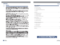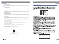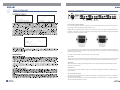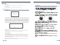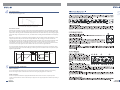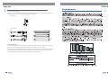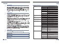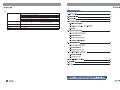
1
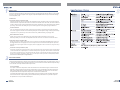
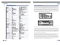
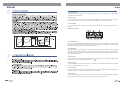
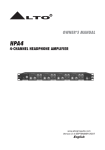
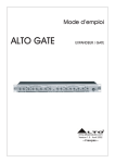
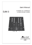
A3
A4
A5
NH00149 2:1/NH00231 1:2
TCL-2
0.072KG/1
TCL-2 TOPP PRO_V1.0
-RS
NF03520
TOPP PRO
SEIKAKU TECHNICAL GROUP LIMITED
18
NPD-TO-1008001
9PCS
JAN.06.2011
TCL
TCL-2
THRESHOLD
GAIN REDUCTION(dB)
30 27 24 21 18 15 12 9
0
SC EXTERANL
35
2.5
60
0
7
1.5
6
4
INPUT / OUTPUT LEVEL(dB)
24 18 12
1
2
6
0
30
30
4
+10
10
2
0.3
15
70
1
150
6
110
0.5
0.1
3
+10
10
THRESHOLD
GAIN REDUCTION(dB)
30 27 24 21 18 15 12 9
0
SC EXTERANL
CH1
0
1.5
LIM
6 12 18
SMART
10
35
+12
+18
+4
2.5
60
0
7
1.5
6
4
INPUT / OUTPUT LEVEL(dB)
24 18 12
1
2
6
0
30
30
4
+10
10
2
0.3
15
70
1
150
110
6
0.5
0.1
CH2
0
1.5
LIM
6 12 18
SMART
10
+12
ON
3
10
+10
+15
OFF
dBu
8
1.2
40
+20
dBu
1:N
SC MONITOR
THRESHOLD
RATIO
EXPANDER / GATE
NF03520-1.0
THRESHOLD
1
N:1
SC FILTER
RATIO
dB/mSec
ATTACK
5
0.05
MANUAL
AUTO
COMPRESSOR
20
+20
dB
dB/Sec
I/O METER
RELEASE
OUTPUT GAIN
0
BYPASS
COMP
OFF
dBu
THRESHOLD
LIMITER
+15
OFF
DUAL MONO
CH 1 MASTER
COUPLE
dBu
8
1.2
40
+20
dBu
1:N
SC MONITOR
THRESHOLD
RATIO
EXPANDER / GATE
THRESHOLD
1
N:1
dB/mSec
SC FILTER
RATIO
ATTACK
5
0.05
MANUAL
AUTO
COMPRESSOR
20
+20
dB
dB/Sec
I/O METER
RELEASE
OUTPUT GAIN
0
BYPASS
COMP
OFF
dBu
OFF
THRESHOLD
LIMITER
TCL-2
COMPRESSOR/
LIMITER/GATE
+18
+4
R
POWER
TABLE OF CONTENTS
1. INTRODUCTION......................................................................................................................................4
2. THE CONCEPT BEHIND........................................................................................................................ 4
2.1 Some technical stuff
2.2 Voltage Controlled Amplifier (VCA)
2.3 Inputs
3. CONTROLS........................................................................................................................................6
3.1 Expander/Gate Section
3.2 Compressor Section
3.3 Peak Limiter Section
3.4 Connectors on The Rear Panel
4. READY TO ROLL?.................................................................................................................................10
4.1 Expander/Gate Section
4.2 Compressor Section
4.3 Peak Limiter Section
5. INSTALLATION AND CONNECTION.....................................................................................................12
5.1 Mains Connection
5.2 Audio Connection
5.3 Rack Mounting
6. TECHNICAL SPECIFICATIONS ................................................................................................................................ 15
7. WARRANTY .......................................................................................................................................................... 17
INTRODUCTION
You are now the Owner of an TOPP PRO TCL-2 Compressor/Limiter/Gate. The TCL-2 is a very powerful dynamic
processor. We have included in it with several innovative circuit designs that make the ATCL-2 a very versatile
processor: smart and fast recognition of the program, adjustable Expander/Gate and very low distortion Voltage
Control Amplifier (VCA).
Feature List:
Smart Knee Control Compressor (SKC)
Soft knee or hard knee? This is the question! SKC combines both: In the "soft knee" mode you control the program
material so that the compression will be the most musical and inaudible. On the other end, the hard knee function
is used for better precision, limiting signal peaks with precision and will allow you to add creativity to the dynamic
processing. This function also allows you to protect other equipment in the signal loop against distortion.
The AUTO Function
Your TCL-2 includes AUTO function switch on the front panel. Thanks to the AUTO function attack and release
times of the program materials are automatically analysed. Then the dynamic range of the program is heavily
compressed in a very musical way so that there will not be any audible breathing or pumping effect.
Attack and Release Controls:
Ok,Ok, you do not want to get advantage of our AUTO function and be the Master of your own mix.
We have provided your TCL-2 with User Adjustable attack and release time for the best total manual control.
Smart Ratio Control expander (SRC)
During music pauses or when a quiet session occurs, the noise floor maybe highly amplified and this effect may
be exaggerated because of inappropriate use of the expansion ratio. The SRC control will adjust the expansion
depending on the input signal so that those signals, which are slightly above the noise floor level, will get the major
benefits.
Smart Gain Control peak limiter (SGC)
This function includes two important functions: Clipper and program limiter. The peak limiter will be activated above
a certain threshold that is adjusted by the User and will radically restrict signal peaks. But what about if the threshold
of the Limiter is surpassed only for a few milliseconds? SGC will turn on automatically and reduce theoutput signal
so that you will not hear any distortion. Smart, isn't it? The SGC proves to be very efficient in loud-speaker protection
and to reduce undesired peaks in digital situations.
THE CONCEPT BEHIND
Some technical stuff
Good old analog technology: It will allow us to manufacture audio equipment with a very high dynamic range: up
to 125 dB. But the dynamic range of digital equipment is more or less 25 dB. A further reduction in dynamic range
occurs with the use of tape recorders and/or vinyl records.
It is not just Music
Yes, a piece of electronic will produce some noise. When the current flows through a conductor this will
generate a certain movement of the electrons and therefore: noise. And throughout the whole spectrum of
audio. Imagine what happens when this inherent noise will be amplified. Yes, today one can use "low-noise"
components but still such components will present a certain level of residual noise.
For example with tape recorders it will not be possible to get an S/N (signal to noise) ratio better than 70dB.
This level would not be accepted today by the increased sensitivity of the listeners. It is possible to improve
the performance of a tape recorder: Absolutely no!
4
Introducing Audio Dynamics
The human ear can detect the noise generated by falling leaves as well as the roar generated by the taking
off space shuttle. Unfortunately no analog, nor digital device can reproduce such wide spectrum. Please
look at Chart.1 and you will see the difference when dynamic capacity of various devices compare to the
human ear. More problems occur when handling high level signals and low level signals. When you reach
the high level limit you may incur in distortion because of the dynamic range of the instrument therefore a
certain "reserve" must be maintained to avoid distortion. This reserve is known as "headroom" and it is usually set at 10-20 dB. Would not be easier just to reduce the operating level? Yes it would but you would put
low level music signals at the same level of the basic noise floor so the overall quality of the signal would
be highly deteriorated. Please look at Chart. 2 and note the Usable dynamic range (including headroom)
versus high level distortion generated by peaks, and Noise floor level.
Chart. 1 The dynamic range capabilities of various devices
Clipping Aera
Noise Aera
Clipping Signal heavily distrorted
Low level signal drowned out by noise
Chart. 2 The interactive relationship between the operating level and the headroom
So the operating level must be as high as possible but not high enough to generate distortion.
There is a very easy way to obtain this. With the volume knob in hand you can increase the volume during
low passages and decrease the volume during loud passages. Unfortunately even the Great Houdini would
not be fast enough to monitor carefully the speed of the musical signal and it would be impossible to detect
signal peaks and consequently levelling them out. Manual control is therefore out of question. The answer
is AGC (automatic gain control); a device that will monitor the signal in real time and that will adjust the gain
for the best S/N ratio without producing distortion. So, the name of this device is "Compressor/limiter".
More technical stuff about Compressor/Limiters
Try to measure the dynamic range of musical instruments. You will find out that your ear will handle such
range during which the distortion and overloading will be generated in your audio equipment.
To avoid these, compressor/Limiters will be used. Both Compressors and Limiters more or less do the same
job but Limiters brutally limit the audio signal above a set threshold, while Compressors handle signal in a
much more civilised way and over a wide range of levels. If an audio signal exceeds the threshold set by
the User the limiter will kill any audio signal above that threshold. Period! Also Compressors perform their
function when the audio signal exceed a certain threshold but the signal is not killed brutally. The audio signal
will be reduced in gain in proportion with the amount above the set threshold.
5
More about noise: Expanders and Noise-Gates
A lot of instruments such as microphones, amplifiers, guitar pickups, etc generate some noise, either at low
frequencies (hum) or at high frequencies (hiss) such noise will inevitably interfere with the quality of your
audio signal. Now, if you scream into a microphone you will not hear the noise generated by such microphone because such noise will be "masked" by the higher level of the signal, your voice in this case.
But if you sing into your microphone more gently in a soft passage, the level of the signal generated by your
voice will get much closer to the floor noise level and such floor noise will become disturbing. In order to kill
this problem Expanders and noise-gates are used. An expander is the opposite of a compressor: attenuating
the signal when the amplitude drops they can limit the floor noise.
Now, we do not need dramatic expansion of a signal across the range, This would generate a resulting dynamic range of over 150dB. For this reason the amplitude control will be applied only to those audio signals
which are below a set threshold. Those audio signals above the set threshold will not be affected. Noisegate can be regarded as a simple Expander. But the Expander will attenuate the audio signal continuously
below the set threshold while the noise-gate will simply dramatically cut-off the audio signal completely.
Voltage Controlled Amplifier (VCA)
The VCA is the soul of the TCL-2 and it is one of the best components available today in his category thanks
to its excellent performances in terms of distortion, linearity, noise and temperature stability.
Inputs
Take it easy: Balanced Inputs
To make your life easy and clean we have provided TCL-2 with electronically balanced inputs. Even if
you operate at high signal levels, hum and noise will be reduce automatically. There is also a servo-function
that will automatically adjust the internal level when unbalanced connectors are detected. The correction
if of 6dB and it will avoid differences in level in between input and output signal.
CONTROLS
THRESHOLD
GAIN REDUCTION(dB)
0
30 27 24 21 18 15 12 9
SC EXTERANL
35
2.5
60
0
7
1.5
6
4
INPUT / OUTPUT LEVEL(dB)
24 18 12
1
2
6
0
30
30
4
+10
10
2
0.3
15
70
1
150
110
6
0.5
0.1
3
10
+10
GAIN REDUCTION(dB)
0
30 27 24 21 18 15 12 9
SC EXTERANL
CH1
0
1.5
THRESHOLD
LIM
6 12 18
SMART
10
35
+12
+18
+4
2.5
60
0
7
1.5
6
4
INPUT / OUTPUT LEVEL(dB)
24 18 12
1
2
6
0
30
30
4
+10
10
2
0.3
15
70
1
150
110
6
0.5
0.1
CH2
0
1.5
LIM
6 12 18
SMART
10
+12
ON
3
10
+10
+15
OFF
40
8
1.2
dBu
1:N
THRESHOLD
RATIO
+20
dBu
SC MONITOR
THRESHOLD
1
N:1
SC FILTER
RATIO
EXPANDER / GATE
dB/mSec
ATTACK
5
0.05
MANUAL
AUTO
COMPRESSOR
20
+20
dB
dB/Sec
I/O METER
RELEASE
OUTPUT GAIN
0
BYPASS
COMP
OFF
dBu
THRESHOLD
LIMITER
DUAL MONO
CH 1 MASTER
8
1.2
+15
OFF
dBu
1:N
THRESHOLD
RATIO
40
+20
dBu
SC MONITOR
COUPLE
1
N:1
dB/mSec
SC FILTER
THRESHOLD
RATIO
EXPANDER / GATE
ATTACK
5
0.05
MANUAL
AUTO
COMPRESSOR
20
+20
dB
dB/Sec
I/O METER
RELEASE
OUTPUT GAIN
0
BYPASS
COMP
TCL-2
COMPRESSOR/
LIMITER/GATE
+18
+4
R
OFF
dBu
OFF
THRESHOLD
LIMITER
POWER
13
Pic. 1 Front Panel of The ACL2 PRO
Your TCL-2 presents with right and left channels. Each channel is equipped with the same control elements: 7 pushbutton switches, 8 rotary controls and 26 LEDs. You can easily operate the stereo mode via pressing the Couple switch.
The details please refer to following content.
1. Couple Switch
Pressing this push-button for stereo mode operation.
When engaged, the Master channel (channel 1) will take control of both channels and override all the controls
and switches of channel 2 with the exception of the SC Monitor, SC External, SC Filter and Bypass switches as
well as the Peak Limiter control.
4
Expander/Gate Section
-35
2.5
1.5
-60
7
0
+15
OFF
dBu
THRESHOLD
8
1.2
1:N
RATIO
EXPANDER / GATE
2
6
3
Pic. 2 Controls of Expander /Gate section
2. Threshold Control
This control adjusts the threshold level for the Expander / Gate Section in the range of Off to +15dBu. Signals
below this level cause expansion.
3. Ratio Control
This control determines the expansion ratio when the signal drops below the threshold level. The expansion
ratio can be set from 1:1.2 to 1:8 (Low ratio for Expander application or 1:8 for Gate application).
4. Threshold LED
The "+" Led lights up when an audio signal is below the set threshold. The "-" Led lights up in presence of an
expansion
Compressor Section
12
15
6
19
THRESHOLD
GAIN REDUCTION(dB)
-10
-24 -18 -12 -6 0
SMART
30
4
-30
+10
10 6
2
+20
SC FILTER
dBu
THRESHOLD
70
1
150
dB/mSec
ATTACK
3
-10
+10
5
0.05
MANUAL
AUTO
CH2
1.5
0.3
110 0.1
1
N:1
RATIO
6 12 18
0
0.5
15
-40
SC MONITOR
INPUT / OUTPUT LEVEL(dB)
30 27 24 21 18 15 12 9 6 4 2 1
0
SC EXTERANL
18
dB/Sec
RELEASE
+20
I/O METER
dB
OUTPUT GAIN
BYPASS
COMP
COMPRESSOR
13
5
14
7
8
10
9
17 11 16
Pic. 3 Controls of the Compressor Section
5. Threshold Control
This control adjusts the threshold level for the Compressor section in the range of -40dBu to +20dBu. The SKC
(Smart Knee Control) is applied to the audio signal, which is a maximum of 10dB above the set threshold.
Above such level (10dB) a hard knee compression will be applied.
6. Threshold LED
These LED's will show you the state of the input signal in relation to the threshold level. If the input signal
falls below the set threshold level the left "-" LED will light up. This means that no signal is being compressed.
If the input signal rises above the set threshold level, this signal will be compressed and the SKC level will be
shown by the middle "0" LED.
7. Ratio Control
The ratio between the input and output level of audio signals exceeding the set threshold level is determined by
this control. This control is manually adjustable from 1:1 to :1.
8. Attack Control
This control determines how fast the compressor is to respond to audio signals that will exceed the set threshold.
It can be manually adjusted from 1 to 150 ms.
9. Release Control
This control determines how fast is the compressor to return to unity gain when the audio signal falls below the
set threshold level. It can be manually adjusted from 0.05 to 5 seconds.
10.Auto Switch
Who needs attack and release control? Activate this switch and these controls will be deactivated. Attack and
release controls will be automatically set by the unit depending on the program material.
7
11. Output Gain Control
Through this control you can vary the output signal by a maximum of 20dB. In this way you can recover the
level lost during the compression process.
12. SC External Switch
This switch will sever the connection between the audio input and the sidechain path. But at the same time it
will also allow an external signal through the SC return jack present on the rear panel.
13. SC Monitor Switch
You can connect the sidechain control signal to the audio output by mean of this switch and at the same time
you will also mute the audio input. In this way you can also monitor the sidechain signal being returned via
external signal processors.
14. Sidechain Filter Switch
A low-cut filter in the sidechain path is activated by this switch. This eliminates unwanted noise generated by
low frequencies.
15. Smart switch
Hard knee mode will be converted into SKC mode by mean of this switch. If you want to get a very musical
compression and you wish to get the most inaudible compression, use SKC.
16. Bypass Switch
This switch simply turns off the correspondent channel. It can also be used to make an A/B comparison in between
processed and unprocessed signal.
17. Input / Output Meter Switch
When the switch is ON it will read the input level. When it is OFF it will read the output level.
18. Input / Output Level Meter
It will read the actual Input or Output Level. The range goes from -24dB to +18dB.
19. Gain Reduction Meter
It indicated the gain reduction. The range displayed is 1 to 30 dB.
Peak Limiter Section
21
LIM
+12
+4
+18
0
OFF
dBu
THRESHOLD
LIMITER
20
Pic. 4 Controls of the Peak Limiter section
20. Threshold Control
The threshold level of the Peak Limiter is adjusted by this control.
21. Limiter LED
This Led will light up when the Limiter function is activated.
8
Connectors on The Rear Panel
22
AC INPUT
110-120V
220-240V
TIP/PIN 2
RING/PIN 3
SLEEVE/PIN 1
95-120V /210-240V 60-50Hz
Rated Power Consumption 14W
4dBu
210-240V: T200mAL 250VAC
95-120V: T400mAL 250VAC
REPLACE FUSE WITH CORRECT
TYPE ONLY
10dBV
Apparaten skall anslutas till
jordat uttag nar den ansluts
till ett natverk
A101
TIP/PIN 2
RING/PIN 3
SLEEVE/PIN 1
FUSE:
TIP
SLEEVE
SEND
2
TIP
SLEEVE
TIP/PIN 2
RING/PIN 3
SLEEVE/PIN 1
4dBu
26
25
TIP
SLEEVE
RETURN
1
3
OPERATING LEVEL
SIDECHAIN
INPUT
INPUT
OUTPUT
CHANNEL 2
23
TIP
SLEEVE
SEND
2
10dBV
OPERATING LEVEL
OUTPUT
TIP/PIN 2
RING/PIN 3
SLEEVE/PIN 1
RETURN
1
3
SIDECHAIN
CHANNEL 1
24
27
28
Pic. 5 The Rear Panel of The ACL2 PRO
22. Fuse holder / Voltage Selector
This is a dual voltage unit. Before you attempt to connect and operate the unit, please make sure that your
local voltage matches the voltage on the fuse-holder cover.
Caution: The fuse protecting the AC supplies circuits of this unit. The fuse can only be changed by a qualified
technician, in the event of a fault or changing the supply voltage. If the fuse continues to blow after replacing,
discontinue use of this unit before repaired.
220-240V
110-120V
220-240V
THIS IS SET FOR
110V AC TO 120V
AC OPERATION
110-120V
THIS IS SET FOR
220V AC TO 240V
AC OPERATION
The fuse-holder above the AC connector on the rear of the chassis has 3 triangular markers(please refer to
the above pictures), with two of these triangles opposing each other, your unit is set to the operating voltage
printed next to these markers.
To change, pull fuse-holder out and rotate 180 , then push in again.
23. AC Inlet
This connector is meant for the connection of the supplied main cord. Do not insert power cord into unit until
voltage has been correctly set. Do not plug power cord into AC power until voltage has been correctly set.
24. Audio In
These connectors are used to input the signal source. You can input the signal via the balanced 1/4" TRS
phone jack or XLR connector.
25. Audio Out
These connectors are used to output the signal. You can output the signal via the balanced 1/4" TRS phone jack
or XLR connector.
26. Operating Level Control
This control is used to adapt this unit to either the -10dBV home recording operating level or the +4dBu professional studio operating level.
The Input / Output Level Meter (18) is referenced automatically to the selected level, i.e. an optimum operating
range of the meter will always be ensured.
9
27. Sidechain Send
Through this 1/4" unbalanced jack the audio signal can be routed to an external processor.
28. Sidechain Return
The return signal of an external processor will be processed through this 1/4" jack.
READY TO ROLL?
Expander/Gate Section
Chart. 3 Function of an expander
As we told you previously in this Manual the downward expander will reduce automatically the level of the audio
signal when such signal is below a set threshold. So the expander is the opposite of the compressor/limiter. We
also explained to you how the ratio curve of the expander is flat while a noise gate it is more brutal processor: It
simply cut-off the entire signal below a certain set threshold. The TCL-2 is equipped with a new kind of expander,
the SRC (Smart Ratio Control). The ratio of the SRC is automatically adjusted according to the audio signal level.
In fact, conventional expanders could easily cut part of the musical program with unacceptable result: The gain
changes become audible. We have equipped the SRC with a non-linear ratio curve, which is soft and adjustable
by the User. Thanks to the SRC low passages close to noise floor level will be processed with a minimum ratio of
expansion while for signals of reduced level a higher ratio will be used with resultant greater attenuation.
SRC CURVE
Chart. 4 SRC Curve characteristics of the Adaptive Expander
Threshold Adjustment
The threshold control covers a very wide range and it is efficient with any working level. Turn the threshold
control fully counterclockwise and the Expander/Gate section will be completely off.
Compressor Section
Another Threshold Control?
The compressor threshold control sets the point where the input level starts to be reduced. Let's say the
level is +12dBu and the threshold control is set at +2dBu: In this case up to 10 dB can be compressed. If
the input level is the same and the control is set at -10dBu the maximum compression will be 22dB. The
operating range of the threshold control is -40 to +20dBu. Turn the threshold control fully clockwise and you
will get a threshold level of +20dBu.
You must remember that the degree and the type of compression not only depend on the threshold control
but also on other controls such as Ratio, Attack and Release.
10
Ratio control
This control sets the change of input level to output level but only for the signals that exceed the threshold.
The scale of the ratio control on the front panel (calibrated in dB) indicates how much input level is required
to increase the output level by 1 dB. If you have a ratio equal to 1:1 you will get the same level of input and
output signal: So, no level change.
If you have a ratio of 2:1 this means that for every 2dB increase of the input level (above threshold) you will
get an increase of output level of 1 dB. ON the same way, a ratio of 10:1 means that for every 10 dB increase
of the input level (above threshold) you will get an increase in output level equal to 1dB, and so on.
You need to be aware that higher ratio settings produce less natural sounds so if you wish a more minute
effect on the dynamic range of a program you should use a Ratio of 4:1 or lower.
With the SKC circuit (Smart Knee Control) you can avoid aggressive compression generated by using high
ratios. How we achieve this? Introducing a "soft knee" curve in the range of up to 10dB above the threshold
level. Hard Knee compression is then used beyond this range.
Output
Threshold
Gain 0 dB
Ratio 2:1
Ratio 4:1
Hard Knee
Limiter
:1
SKC Curve
Input
Chart. 5 SKC characteristic of the compressor section
Attack control
The attack time represents the amount of time that passes before the compressor start to lower the output
level when the signal is above the threshold point.
For very fast transients such as drums, handclaps, etc, a short attack time will be used. These peaks are
consequently carefully regulated by the compressor. Sounds of other nature will get advantages if longer
attack times are used. Anyway, our advice is always to begin the process with longer attack times. Then you
can start gradually to reduce the attack time. IN the TCL-2 the attack time can be set in a range of 1 to
150 milliseconds.
Release Control
This control determines how much time the compressor needs to get back to normal gain when the audio
signal falls below the set threshold.
A too short release time will make the volume to fluctuate and you will experience pumping effect. A too long
release time will give you pumping and breathing effect especially when you have loud passage followed by
a quite passage. The release time on TCL-2 can be set from 0.05 to 5 seconds.
Auto switch
This switch turns off the possibility of manually set the attack and release times. An intelligent program recognition circuit will automatically set the attack and release times. In such way, undesirable effects such
as distortion and pumping will be avoided.
Output control
This Control is indispensable to compensate the loss of level at output level generated by the gain reduction
caused by the compression and limiting processing.
Bypass Switch
This switch simply turns off the correspondent channel. This is useful to compare quickly the processed
and unprocessed signal.
11
Gain Reduction Meter
This consists of 12 LED on the front of the TCL-2. Through this Led meter you can visualise the amount
of gain reduction at any given time.
Chart. 6 The effect of a compressor can be expressed as the amount
of gain reduction that is taking place for any given input
Peak Limiter Section
How fast is the compressor to react to a signal which is above the threshold point? This is determined by the attack
time. A longer attack time is advisable to process low frequencies while shorter attack time is preferable for high
frequencies. In this way you will avoid undesired dynamic distortion. But what about if you are mixing a program
with a wide range of frequencies? In this case you should choose a setting that would benefit the low frequency
better.
Well, life is not that easy for conventional compressor/limiters. Ok you handle an audio signal made by a wide
range of frequencies and you have chosen a longer attack time. But, if using your TCL-2 as a limiter the
fast high frequencies will pass through untouched because the attack time is too slow and such transients could
cause distortion when the unit is connected to broadcast devices or tape recorders. The solution in TCL-2 is
represented by our Smart Gain Control (SGC) limiter circuit. The curve in bold is the output signal and the dashed
curve above it is the input signal. The area in between the two is the amount of gain reduction.
The unit will activate the limiter when the signal exceeds the threshold for more than 15 microseconds. Then 1
second after that the signal is below threshold again, reduction goes back to 0dB and in this case input and output
signals are again identical.
Peak Limiting
Level
Program Limiting
Release
Threshold
Input
Output
6ms
10
20
15ms
approx. 1 s
t/ms
30
Chart. 7 SGC characteristic of the limiter section
INSTALLATION AND CONNECTION
Mains Connection
TCL-2 is provided with dual voltage plug. You must check the power supply Voltage available in your Country
before connecting the power cord in the wall outlet. Please see Page9, paragraph 22 for further info.
Audio connection
The TCL-2 Compressor/Limiter/Gate is equipped with balanced XLR connectors as well as 1/4" phone jack and
can be connected with other units in different ways to support a vast range of applications without experiencing a
signal loss.
12
a. Wiring Configuration
Both types of connectors available on TCL-2 can be wired in balanced and unbalanced modes.
Please see following drawing for details:
For 1/4" Phone jack
+
+
-
Tip
Ring
+
Tip
Tip
Ring
Sleeve
Sleeve
TS Type Unbalanced
Sleeve
TRS Type Balanced
TRS Type Unbalanced
For XLR connector
Pin2 (+)
Pin2 (+)
Pin3 (-)
Pin3 (-)
(Linked to Pin1 manually,
)
Pin1 ( )
Pin1 ( )
XLR Type Unbalanced
XLR Type Balanced
b. In Line Connection
Please see following drawing for details.
Balanced
TIP RING SLEEVE
SLEEVE RING TIP
3
3
1
1
2
2
1
3
2
TIP RING SLEEVE
Tip
Ring
Sleeve
Tip
Ring
Sleeve
1
2
1
2
3
3
Tip
Ring
1
2
3
Sleeve
Unbalanced
1
3
2
Tip
Ring
Sleeve
TIP RING SLEEVE
Tip
1
3
2
Sleeve
1
2
3
1
2
3
1
TIP SLEEVE
2
3
1
2
3
Tip
TIP SLEEVE
SLEEVE TIP
Sleeve
Tip
Ring
TIP RING SLEEVE
SLEEVE RING TIP
Cent r e
Screen
Tip
Sleeve
Tip
Ring
Sleeve
Sleeve
Tip
Cent r e
Sleeve
Screen
Tip
Ring
Centre
Sleeve
Screen
TIP SLEEVE
TIP RING SLEEVE
2
2
3
3
1
1
1
2
3
1
2
3
13
c. Insert Points Connection
In case you are using the main inserts of your mixing console and you have a single jack for SEND and
RETURN, you can use an insert Y cable. Please see following drawing.
1/4" TRS insert
Send
Return
Tip
Ring
Sleeve
Insert Leads
SLEEVE TIP
TIP RING SLEEVE
Tip
Ring
Sleeve
Tip (Send)
Sleeve
Tip (Return)
Sleeve
SLEEVE RING TIP
1
2 (Send)
1
3
2
2
Tip
Ring
Sleeve
3
1
TIP RING SLEEVE
3
1
2 (Return)
3
Tip
Ring
Sleeve
TIP RING SLEEVE
Centre (Send)
Screen
Centre (Return)
Screen
5.3 Rack Mounting
The most secure mounting is on a universal rack shelf available from various rack manufactures or your music
dealer. The TCL-2 PRO Compressor /Limiter /Gate fits into one standard 19" rack unit of space.
Please allow at least an additional 4" depth for the connectors on the rear panel. Be sure that there is enough air
space around the unit for sufficient ventilation and please do not place the TCL-2 Compressor /Limiter /Gate
on high temperature devices such as power amplifiers etc. to avoid overheating.
14
TECHNICAL SPECIFICATIONS
AUDIO INPUT
AUDIO OUTPUT
Type
Active balanced XLR and 1/4"JACK
Impedance
Balanced: 50K Ohm
Operating Level
+4dBu /-10dBV
Maximum input level
Balanced and Unbalanced: +21 dBu
CMRR
Type
Unbalanced: 25K Ohm
>55dB @1KHz
Impedance
XLR and 1/4" JACK
Balanced: 60 Ohm
Maximum output level
Bandwidth
+21 dBu
20Hz to 20KHz at +0,-0.5dB
THD +N%
Unbalanced: 30Ohm
0.01% typ.1KHz, @+4dBu
0.04% typ,1KHz, @+20dBu
SC RETURN
SC SEND
EXPANDER/GATE SECTION
COMPRESSOR SECTION
PEAK LIMITER SECTION
IMD
0.01% typ
Noise
Crosstalk
Type
>-90dBu
<-100dB
Impedance
>10K Ohm
Maximum input level
Type
+24dBu
1/4"JACK
Impedance
Maximum output level
2K Ohm
+21dBu
Type
Threshold
Smart ratio control Expander
Variable: from OFF to +15dB
Ratio
Variable: from 1:1.2 to 1:8
Type
Smart knee control compressor
Threshold
Variable: from -40dB to +20dB
Ratio
Variable: from 1:1 to
Manual Attack Time
Variable: from 1ms to 150ms
Manual Release Time
Variable: from 0.05ms to 5s
Auto Attack Time
Typ. 15ms at 10dB; 5ms at 20 dB; 3ms at 30dB
Auto Release Time
Typ. 125dB/s
Output
Variable; -20dB to +20dB
Type
Smart Gain Control peak limiter
Threshold
Variable: from 0 to OFF
Ratio
:1
:1
Stage 1:
Clipper
Attack and Release
zero
Stage 2
Program Limiter
Attack
typ. <5ms
typ. 20dB/s
Release
FUNCTION SWITCHES
1/4"JACK
COUPLE
Linking CH1 ( master ) and CH2; stereo operation
OPERATING LEVEL
BYPASS
Internal reference level: from +4dBu to -10dBV
Bypass switch
I/O METER
Switches input and output for the level meter
AUTO
Enables the program dependent setting of
the ATTACK and RELEASE times
SC EXTERNAL
Switches the detector section to the external
SC input
SC MONITOR
Monitoring the external SC input, disengaging
the normal audio
SMART
Enables the ` Smart Knee Control ` characteristics
SC FILTER
Allows for frequency dependent detection
15
16
INDICATORS
GAIN REDUCTION: 12 element LED
INPUT / OUTPUT LEVEL: 8 element LED
EXPANDER/GATE THRESHOLD: 2 element LED ( under"+" above"-")
COMPRESSOR THRESHOLD: 3 element LED ( under"+" smart "0" above"-" )
PEAK LIMITER THRESHOLD: 1 element LED (Limiter Function )
Function switch: LED indicator for each
POWER SUPPLY
95-120V
POWER CONSUMPTION
14 Watts
DIMENSIONS
483(W) 194.5(D) 44(H)mm (19" 7.7" 1.7")
WEIGHT
3.1kg(6.83lb)
/210-240V
,60-50Hz FUSE:
210-240V: T200mAL 250VAC
95-120V: 400mAL 250VAC
WARRANTY
1. WARRANTY REGISTRATION CARD
To obtain Warranty Service, the buyer should first fill out and return the enclosed Warranty Registration Card within
10 days of the Purchase Date.
All the information presented in this Warranty Registration Card gives the manufacturer a better understanding of
the sales status, so as to purport a more effective and efficient after-sales warranty service.
Please fill out all the information carefully and genuinely, miswriting or absence of this card will void your warranty
service.
2. RETURN NOTICE
2.1 In case of return for any warranty service, please make sure that the product is well packed in its original shipping
carton, and it can protect your unit from any other extra damage.
2.2 Please provide a copy of your sales receipt or other proof of purchase with the returned machine, and give detail
information about your return address and contact telephone number.
2.3 A brief description of the defect will be appreciated.
2.4 Please prepay all the costs involved in the return shipping, handling and insurance.
3. TERMS AND CONDITIONS
3.1 TOPP PRO warrants that this product will be free from any defects in materials and/or workmanship for a period
of 1 year from the purchase date if you have completed the Warranty Registration Card in time.
3.2 The warranty service is only available to the original consumer, who purchased this product directly from the
retail dealer, and it can not be transferred.
3.3 During the warranty service, TOPP PRO may repair or replace this product at its own option at no charge to you
for parts or for labor in accordance with the right side of this limited warranty.
3.4 This warranty does not apply to the damages to this product that occurred as the following conditions:
Instead of operating in accordance with the user's manual thoroughly, any abuse or misuse of this product.
Normal tear and wear.
The product has been altered or modified in any way.
Damage which may have been caused either directly or indirectly by another product / force / etc
Abnormal service or repairing by anyone other than the qualified personnel or technician.
And in such cases, all the expenses will be charged to the buyer.
3.5 In no event shall TOPP PRO be liable for any incidental or consequential damages. Some states do not allow the
exclusion or limitation of incidental or consequential damages, so the above exclusion or limitation may not apply to you.
3.6 This warranty gives you the specific rights, and these rights are compatible with the state laws, you may also have
other statutory rights that may vary from state to state.
17
TCL