1
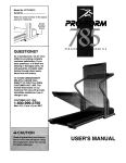
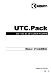
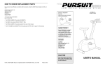
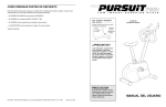
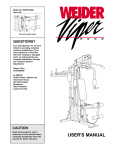
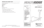
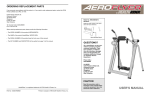
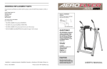
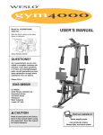
HOW TO ORDER REPLACEMENT PARTS
If you encounter any difficulties or problems with this product, contact the ICON Fitness Lifestyle Ltd. office, or
write:
ICON Fitness Lifestyle Ltd.
Greenwich House
223 North Street
Sheepscar
West Yorkshire
Leeds LS7 2AA
CLASS HC
Fitness Product
Model No. WLEX69571
Serial No.
Write the serial number in the space
above for future reference.
Tel: Country Code: 0345-089009
Fax: 0113-2411120
Serial
Number
Decal
• The MODEL NUMBER of the product (WLEX69571).
• The NAME of the product (WESLO PURSUIT® 795i).
• The SERIAL NUMBER of the product (see the front cover of this manual).
• The KEY NUMBER and DESCRIPTION of the part(s) (see the PART LIST on page 14 of this manual).
QUESTIONS?
As a manufacturer, we are committed to providing complete
customer satisfaction. If you
have questions, or find that there
are missing or damaged parts,
we will guarantee you complete
satisfaction through our
Customer Service Department.
Please CALL:
0345-089009
Or WRITE:
ICON Fitness Lifestyle Ltd.
Greenwich House
223 North Street
Sheepscar
West Yorkshire
Leeds LS7 2AA
CAUTION
Read all precautions and instructions in this manual before using
this equipment. Keep this manual
for future reference.
Part No. 145329 R0398A WESLO is a registered trademark of ICON Health & Fitness, Inc. © 1998
Printed in China
USER'S MANUAL
EXPLODED DRAWING—Model No. WLEX69571
R0398A
40
3
6
TABLE OF CONTENTS
2
7
IMPORTANT PRECAUTIONS . . . . . . . . . . . . . . . . . . . . . . . . . . . . . . . . . . . . . . . . . . . . . . . . . . . . . . . . . . . . .3
BEFORE YOU BEGIN . . . . . . . . . . . . . . . . . . . . . . . . . . . . . . . . . . . . . . . . . . . . . . . . . . . . . . . . . . . . . . . . . . .4
PART IDENTIFICATION CHART . . . . . . . . . . . . . . . . . . . . . . . . . . . . . . . . . . . . . . . . . . . . . . . . . . . . . . . . . . .5
ASSEMBLY . . . . . . . . . . . . . . . . . . . . . . . . . . . . . . . . . . . . . . . . . . . . . . . . . . . . . . . . . . . . . . . . . . . . . . . . . . .6
HOW TO USE THE PURSUIT 795i . . . . . . . . . . . . . . . . . . . . . . . . . . . . . . . . . . . . . . . . . . . . . . . . . . . . . . . . .8
CONDITIONING GUIDELINES . . . . . . . . . . . . . . . . . . . . . . . . . . . . . . . . . . . . . . . . . . . . . . . . . . . . . . . . . . . .10
MAINTENANCE AND TROUBLE-SHOOTING . . . . . . . . . . . . . . . . . . . . . . . . . . . . . . . . . . . . . . . . . . . . . . . .12
PART LIST . . . . . . . . . . . . . . . . . . . . . . . . . . . . . . . . . . . . . . . . . . . . . . . . . . . . . . . . . . . . . . . . . . . . . . . . . . .14
EXPLODED DRAWING . . . . . . . . . . . . . . . . . . . . . . . . . . . . . . . . . . . . . . . . . . . . . . . . . . . . . . . . . . . . . . . . .15
HOW TO ORDER REPLACEMENT PARTS . . . . . . . . . . . . . . . . . . . . . . . . . . . . . . . . . . . . . . . . . . .Back Cover
63
3
1
10
5
11
19
41
8
12
27
9
41
26
53
14
25
53
21
16
24
21
9
20
9
41
54
8
9
23
24
31
25
27
29
61
8
22
41 8
41
15
31 9
54
17
26
60
32
50
49
50
60
33
56
57
58
59
44
36
39
37
62
43
4
38
31
48
34
35
37
36
18
4
48
30
2
45
43
31
4
47
52
34
35
30
46
55
59 42
51
4
28
13
33
15
PART LIST—Model No. WLEX69571
Key No. Qty.
1
2
3
4
5
6
7
8
9
10
11
12
13
14
15
16
17
18
19
20
21
22
23
24
25
26
27
28
29
30
31
32
33
1
1
5
4
1
2
1
5
8
1
1
1
1
1
1
1
1
1
1
1
3
1
1
2
2
2
2
1
1
4
4
1
1
Description
R0398A
Key No. Qty.
Left Side Shield
Right Side Shield
Double Tree Fastener
Side Shield Screw
Handlebar
Foam Grip
Console
M10 x 25mm Button Screw
M4 x 16mm Screw
Resistance Knob
Resistance Cable
Knob Housing
Right Pedal
Handlebar Post
Frame
Belt
Front Stabiliser
Rear Stabiliser
Seat
Seat Post
M8 Nylon Locknut
25.4mm x 50.8mm Bushing
38.1mm x 63.5mm Bushing
Wheel Hub
Wheel
Wheel Spacer
M6 x 16mm Self-tapping Screw
Left Pedal
Seat Knob
M10 x 70mm Carriage Bolt
M10 Nylon Locknut
Small Spring
Crank/Pulley
34
35
36
37
38
39
40
41
42
43
44
45
46
47
48
49
50
51
52
53
54
55
56
57
58
59
60
61
62
63
#
#
#
2
2
2
2
1
1
1
5
1
2
1
1
1
1
2
1
4
1
1
3
1
1
1
1
1
2
2
1
1
2
1
1
1
Description
M8 Washer Nut
Adjustment Bolt
Adjustment Bracket
M6 Nut
Flywheel Axle
Flywheel
Side Shield Cover
M10 Split Washer
Notched Crank Nut
Flywheel Bearing
M10 Washer
M4 x 16mm Flat Head Screw
Strap Buckle
Resistance Strap
Stabiliser Endcap
Large Spring
M6 Washer
M4 x 14mm Bolt
M4 Nut
M8 Split Washer
Reed Switch/Wire
Magnet
Crank Nut
Notched Crank Washer
Slotted Crank Nut
Bearing
Bearing Cup
Crank Washer
Flywheel Spacer
Handlebar Endcap
User’s Manual
Console Decal Sheet
Allen Wrench
Note: “#” indicates a non-illustrated part. Specifications are subject to change without notice. See the back cover
of this manual for information about ordering replacement parts.
14
IMPORTANT PRECAUTIONS
WARNING: To reduce the risk of serious injury, read the following important precautions before
using the exercise cycle.
1. Read all instructions in this manual before
using the exercise cycle. Use the exercise
cycle only as described.
7. Wear appropriate clothing when exercising; do
not wear loose clothing that could become
caught on the exercise cycle. Always wear
athletic shoes for foot protection.
2. It is the responsibility of the owner to ensure
that all users of the exercise cycle are adequately informed of all precautions.
8. When adjusting the seat, insert the seat knob
through one of the holes in the seat post
(see the drawing on page 4). Do not insert
the seat knob under the seat post.
3. Use the exercise cycle indoors, away from
moisture and dust. Place the exercise cycle
on a level surface, with a mat beneath it to
protect the floor or carpet from damage.
9. Always keep your back straight when using
the exercise cycle. Do not arch your back.
4. Inspect and tighten all parts regularly.
Replace any worn parts immediately.
10. If you feel pain or dizziness at any time while
exercising, stop immediately and begin cooling down.
5. Keep children under the age of 12 and pets
away from the exercise cycle at all times.
11. The exercise cycle is intended for in-home
use only. Do not use the exercise cycle in a
commercial, rental, or institutional setting.
6. The exercise cycle should not be used by
persons weighing more than 250 pounds
(115 kg).
WARNING: Before beginning this or any exercise program, consult your physician. This is especially important for persons over the age of 35 or persons with pre-existing health problems. Read
all instructions before using. ICON assumes no responsibility for personal injury or property damage sustained by or through the use of this product.
The decal shown at the right
has been placed on the exercise
cycle. If the decal is missing, or
if it is not legible, please call
our Customer Service
Department to order a free
replacement decal. Apply the
replacement decal in the location shown.
3
HOW TO ADJUST THE RESISTANCE STRAP
BEFORE YOU BEGIN
Thank you for selecting the new WESLO PURSUIT®
795i exercise cycle. The PURSUIT 795i blends
advanced engineering with contemporary styling to
provide you with a low-impact workout in the convenience and privacy of your own home.
please mention the product model number and serial
number when calling. The model number is
WLEX69571. The serial number can be found on a
decal attached to the PURSUIT 795i (see the front
cover of this manual for the location of the decal).
For your benefit, read this manual carefully before
you use the PURSUIT 795i. If you have additional
questions, please call our Customer Service
Department at 0345-089009. To help us assist you,
Before reading further, please look at the drawing
below and familiarise yourself with the parts that are
labelled.
Water Bottle Holder
(bottle is not included)
Handlebars
Console
Book Rack
Resistance Knob
Next, use an
adjustable
wrench to turn
16
the right pedal
counterclockwise and
remove it.
Remove the
right side
shield.
Press down on
the centre of
the Belt (16) between the front and rear pulleys.
There should be from 1/4” to 3/4” of vertical
movement in the centre of the Belt.
If there is not enough pedalling resistance when the
resistance knob is turned to the highest setting, the
Resistance Strap (47) may need to be adjusted. To
adjust the Resistance Strap, the left side shield must
first be removed. Refer to the instructions at the left
and remove the left side shield.
Next, turn the
resistance knob
to the lowest setting. Locate and
47
open the Strap
33
Buckle (46). Grip
46
the end of the
Resistance Strap
(47) and pull it up
to remove any
slack. While
holding the end
of the Resistance Strap, fully close the Strap Buckle.
Turn the Crank (33) for a moment to make sure that
there is not too much resistance. When the Resistance Strap is properly adjusted, reattach the left side
shield and pedal.
If the Belt (16)
is properly
adjusted, reat16
tach the side
shields and ped39
als. If the Belt
needs to be
adjusted, loosen
the M8 Washer
34
37
Nut (34) on
each side of the
Flywheel (39).
To tighten the Belt, turn the two M6 Nuts (37) clockwise; to loosen the Belt, turn the Nuts counterclockwise. Make sure that the Flywheel is straight and tighten the M8 Washer Nuts (34). Reattach the side shields
and pedals.
HOW TO ADJUST THE BELT
Seat
The exercise cycle features a precision belt that must
be kept properly adjusted. If the belt causes excessive noise or slips as you pedal, the belt should be
checked. To do this, the left side shield must first be
removed. Refer to the instructions on page 12 and
remove the left side shield.
Seat Post
Seat Knob
FRONT
Pedal
Front Wheels
BACK
RIGHT SIDE
4
13
MAINTENANCE AND TROUBLE-SHOOTING
PART IDENTIFICATION CHART
Inspect and tighten all parts of the exercise cycle
regularly. Replace any worn parts immediately.
Use the chart below for help identifying the small
parts used in assembly. The number in parenthesis
below each part refers to the key number of the part.
The second number refers to the quantity used in
HOW TO ADJUST THE REED SWITCH
If the console does not display correct feedback, the
reed switch should be adjusted. In order to adjust the
reed switch, the Left Side Shield (1) must be removed.
Using an adjustable wrench, turn the Left Pedal (28)
The exercise cycle can be cleaned with a soft, damp
cloth. Avoid spilling liquid on the console. Keep the
console out of direct sunlight or the display may be
damaged. Remove the batteries when storing the
exercise cycle.
assembly. Note: Some parts may have been preattached for shipping purposes. If a part is not
found in the parts bag, check to see if it has been
pre-attached.
40
HOW TO TIGHTEN THE CRANK
33
28
If the arms of the Crank (33) become loose, they
should be tightened in order to prevent excessive
wear. Loosen the Crank Nut (56) on the left arm of the
M8 Nylon Locknut (21)–3
M10 Nylon Locknut (31)–4
M10 x 25mm Button Screw (8)–5
1
M4 x 16mm Screw (9)–5
58
M8 Split Washer (53)–3
56
4
33
clockwise and remove it from the Crank (33). Remove
the two Side Shield Screws (4) from the Left Side
Shield. Next, lift the Side Shield Cover (40) off the
Side Shields. Grasp both Side Shields at the top and
gently pull them apart. Make sure that the arm of the
Crank is in the position shown in the drawing above.
Carefully slide the Left Side Shield forward off the arm
of the Crank and remove it.
Crank. Place the end of a standard screwdriver in one
of the slots in the Slotted Crank Nut (58). Lightly tap
the screwdriver with a hammer to turn the Slotted
Crank Nut counterclockwise until the arms are no
longer loose. Do not overtighten the Slotted Crank
Nut. When the Slotted Crank Nut is properly tightened, retighten the Crank Nut.
M10 x 70mm Carriage Bolt (30)–4
Next, locate the
Reed Switch (54).
Turn the Crank (33)
9
until the Magnet
33
55
(55) is aligned with
the Reed Switch.
Loosen but do not
remove the M4 x
54
16mm Screw (9).
Slide the Reed
Switch slightly closer to or away from
the Magnet. Retighten the Screw. Turn the Crank for a
moment. Repeat until the console displays correct
feedback. When the Reed Switch is correctly adjusted, reattach the left side shield and pedal.
BATTERY REPLACEMENT
If the console does not function properly, the batteries
should be replaced. To replace the batteries, see
assembly step 2 on page 6. In addition, make sure
that the console wire is connected to the reed switch
wire.
12
5
M10 Split Washer (41)–5
SUGGESTED STRETCHES
ASSEMBLY
Place all parts of the PURSUIT 795i in a cleared area and remove the packing materials. Do not dispose of
the packing materials until assembly is completed.
Assembly requires the included allen wrench
adjustable wrenches
.
, a phillips screwdriver
1. Identify the Front Stabiliser (17), which has Wheels
(25) on the ends. Hold the Front Stabiliser against
the saddle on the front of the Frame (15). Make
sure that the Front Stabiliser is turned so the square
holes are facing away from the saddle. Attach the
Front Stabiliser with two M10 x 70mm Carriage
Bolts (30) and two M10 Nylon Locknuts (31).
1
and two
25
31
15
7
2
Batteries
7
Console
Wire
Battery Cover
Insert the console wire through the Handlebar Post
(14). Connect the console wire to the Reed Switch
Wire (54). Attach the Console (7) to the Handlebar
Post with four M4 x 16mm Screws (9).
9
3. Attach the Handlebar (5) to the Handlebar Post (14)
with two M10 x 25mm Button Screws (8) and two
M10 Split Washers (41).
14
9
3. Calf/Achilles Stretch
With one leg in front of the other, reach forward and place
your hands against a wall. Keep your back leg straight and
your back foot flat on the floor. Bend your front leg, lean forward and move your hips toward the wall. Hold for 15 counts,
then relax. Repeat 3 times for each leg. To cause further
stretching of the achilles tendons, bend your back leg as well.
Stretches: Calves, achilles tendons and ankles.
3
4
4. Quadriceps Stretch
5. Inner Thigh Stretch
15
54
8
41
41
8
8
Sit with the soles of your feet together and your knees outward. Pull your feet toward your groin area as far as possible.
Hold for 15 counts, then relax. Repeat 3 times. Stretches:
Quadriceps and hip muscles.
3
8
41
5
6
2
With one hand against a wall for balance, reach back and
grasp one foot with your other hand. Bring your heel as close
to your buttocks as possible. Hold for 15 counts, then relax.
Repeat 3 times for each leg. Stretches: Quadriceps and hip
muscles.
12
Carefully slide the Handlebar Post (14) onto the
Frame (15). Be careful to avoid pinching the
wires inside the Handlebar Post. Attach the
Handlebar Post with three M10 x 25mm Button
Screws (8) and three M10 Split Washers (41).
Attach the Knob Housing (12) to the Handlebar Post
with a M4 x 16mm Screw (9).
1
Stand with your knees bent slightly and slowly bend forward
from your hips. Allow your back and shoulders to relax as you
reach down toward your toes as far as possible. Hold for 15
counts, then relax. Repeat 3 times. Stretches: Hamstrings,
back of knees and back.
Sit with one leg extended. Bring the sole of the opposite foot
toward you and rest it against the inner thigh of your extended
leg. Reach toward your toes as far as possible. Hold for 15
counts, then relax. Repeat 3 times for each leg. Stretches:
Hamstrings, lower back and groin.
30
Attach the Rear Stabiliser (not shown) to the rear of
the Frame (15) in the same manner.
2. The Console (7) requires two 1,5V batteries (not
included). Alkaline batteries are recommended.
Refer to the inset drawing. Open the battery cover
on the underside of the Console as shown. Press
two batteries into the battery compartment. Make
sure that the negative ends of the batteries
(marked “–”) are touching the springs in the
battery compartment. Close the battery cover.
1. Toe Touch Stretch
2. Hamstring Stretch
25
17
The correct form for several basic stretches is shown in the drawings below. Move slowly as you stretch—never
bounce.
14
11
5
4. Tighten the two Side Shield Screws (4) in the Left
Side Shield (1). Next, tighten the two Side Shield
Screws in the Right Side Shield (2).
CONDITIONING GUIDELINES
The following general guidelines will help you to plan
your exercise program. Remember that proper nutrition and adequate rest are essential for successful
results.
Aerobic Exercise
If your goal is to strengthen your cardiovascular system, your exercise must be “aerobic.” Aerobic exercise is activity that requires large amounts of oxygen
for prolonged periods of time. This increases the
demand on the heart to pump blood to the muscles,
and on the lungs to oxygenate the blood. For aerobic
exercise, adjust the intensity of your exercise until
your heart rate is near the highest number in your
training zone.
WARNING: Before beginning this or any exercise program, consult your physician. This is
especially important for persons over the age
of 35 or persons with pre-existing health
problems.
4
40
Press the Side Shield Cover 40) onto the Left and
Right Side Shields (1, 2).
2
1
4
HOW TO MEASURE YOUR HEART RATE
EXERCISE INTENSITY
To measure your heart rate, first exercise for at least
four minutes. Then, stop pedalling and measure your
heart rate using the pulse sensor on the console.
Whether your goal is to burn fat or to strengthen your
cardiovascular system, the key to achieving the
desired results is to exercise with the proper intensity.
The proper intensity level can be found by using your
heart rate as a guide. The chart in the centre of the
console shows recommended heart rates for fat burning, maximum fat burning, and cardiovascular (aerobic) exercise.
WORKOUT GUIDELINES
Each workout should include the following three
important parts:
A warm-up, consisting of 5 to 10 minutes of stretching and light exercise. (See SUGGESTED STRETCHES on page 11.) A proper warm-up increases your
body temperature, heart rate, and circulation in preparation for strenuous exercise.
To find the proper heart rate for you, first find your age
on the left side of the chart (ages are rounded off to
the nearest ten years). Next, find the three numbers
to the right of your age. The three numbers are your
“training zone.” The lowest number is the recommended heart rate for fat burning; the middle number is the
recommended heart rate for maximum fat burning; the
highest number is the recommended heart rate for
aerobic exercise.
5. Insert the Seat Post (20) into the Frame (15). Align
one of the holes in the Seat Post with the hole in
the Frame. Insert the Seat Knob (29) into the Frame
and the Seat Post, and tighten the Seat Knob into
the Frame. Make sure to insert the Seat Knob
through one of the holes in the Seat Post; do
not insert the Seat Knob under the Seat Post.
5
19
Attach the Seat (19) to the Seat Post (20) with three
M8 Nylon Locknuts (21) and three M8 Split Washers
(53). (Note: The Nylon Locknuts and Split Washers
may be pre-attached to the bottom of the Seat.)
53
53
21
21
20
Training zone exercise, consisting of 20 to 30 minutes of exercising with your heart rate in your training
zone. (During the first few weeks of your exercise program, do not keep your heart rate in your training
zone for longer than 20 minutes.)
29
15
Burning Fat
A cool-down, with 5 to 10 minutes of stretching. This
will increase the flexibility of your muscles and will
help to prevent post-exercise problems.
To burn fat effectively, you must exercise at a relatively low intensity level for a sustained period of time.
During the first few minutes of exercise, your body
uses easily accessible carbohydrate calories for energy. Only after the first few minutes of exercise does
your body begin to use stored fat calories for energy.
If your goal is to burn fat, adjust the intensity of your
exercise until your heart rate is near the lowest number in your training zone as you exercise.
EXERCISE FREQUENCY
To maintain or improve your condition, plan three workouts each week, with at least one day of rest between
workouts. After a few months of regular exercise, you
may complete up to five workouts each week, if
desired. Caution: Be sure to progress at your own
pace and avoid overdoing it. Incorrect or excessive
training may result in injury to your health.
For maximum fat burning, adjust the intensity of your
exercise until your heart rate is near the middle number in your training zone as you exercise.
6. Identify the Left Pedal (28); there is an “L” on the
Left Pedal for identification. Using an adjustable
wrench, tighten the Left Pedal counterclockwise into
the left arm of the Crank (33).
33
Tighten the Right Pedal (not shown) clockwise into
the right arm of the Crank (33).
28
Remember, the key to success is make exercise a
regular and enjoyable part of your everyday life.
10
6
7
HOW TO USE THE PURSUIT 795i
HOW TO ADJUST THE SEAT
DIAGRAM OF THE CONSOLE
2. When the power
is turned on, the
Arrow
console will
begin displaying
all modes in a
repeating cycle
(except for the
pulse mode).
Flashing arrows will show which mode is currently
displayed.
HOW TO APPLY AN INFORMATION DECAL TO
THE CONSOLE
For effective
exercise, the
Seat (19) should
be at the proper
height. As you
pedal, there
19
should be a
slight bend in
your knees
when the pedals
are in the lowest
20
position. To
29
adjust the Seat,
first hold the
15
Seat and
unscrew the
Seat Knob (29).
Align one of the
holes in the
Seat Post (20) with the hole in the Frame (15). Insert
the Seat Knob into the Frame and the Seat Post, and
tighten the Seat Knob into the Frame. Caution: Make
sure to insert the Seat Knob through one of the
holes in the Seat Post; do not insert the Seat
Knob under the Seat Post.
All of the information on the
console is printed
in English. The
included decal
sheet contains
the same information in five
other languages.
If English is not
your language,
find the decal on
the decal sheet
that is printed in
your language.
3. To measure your
pulse, stop pedalling and place
your thumb on
the pulse sensor
as shown. The
pulse sensor is
pressure-activated—fully press down the pulse sensor. Do not
press too hard, or the circulation in your thumb
will be restricted, and your pulse will not be
detected. Next, slightly raise your thumb until the
heart-shaped indicator in the display flashes
steadily. Hold your thumb at this level. After 5 to 10
seconds, three dashes will appear in the display
and your pulse will then be shown. Hold your thumb
on the sensor for another 15 seconds for the most
accurate reading. If the displayed pulse appears to
be too high or too low, or if your pulse is not displayed, lift your thumb off the sensor and allow the
display to reset. Press down again on the sensor as
described above.
The console offers six modes that provide instant
exercise feedback. Each mode is displayed for five
seconds in a repeating cycle. The modes are
described below.
Pulse—This mode displays your heart rate
when the pulse sensor is used.
Calorie—This mode displays the approximate
number of calories you have burned.
Fat Calorie—This mode displays the approximate number of fat calories you have burned.
(See BURNING FAT on page 10.)
Speed—This mode displays your pedalling
speed, in kilometres per hour.
HOW TO ADJUST THE PEDALLING RESISTANCE
Next, peel the
information decal
off the decal
sheet. Apply the
decal to the
console in the
location shown.
To vary the
intensity of your
exercise, the
pedalling resistance can be
adjusted. The
resistance is
controlled with
the Resistance
10
Knob (10). To
increase the
resistance, turn
the Resistance
Knob clockwise;
to decrease the
resistance, turn
the Resistance Knob counterclockwise.
Time—This mode displays the length of time
you have exercised.
Make sure that your thumb is positioned as shown,
and that you are applying the proper amount of pressure to the pulse sensor. Try the sensor several
times until you become familiar with it.
Distance—This mode displays the total number
of kilometres you have pedalled during your
workout.
4. To reset the display, press the on/reset button.
HOW TO OPERATE THE CONSOLE
BATTERY INSTALLATION
Before the console can be operated, two 1,5V
batteries must be installed. If you have not installed
batteries, see assembly step 2 on page 6.
8
5. To turn off the power, simply wait for about six
minutes. Note: The console has an “auto-off”
feature. If the pedals are not moved and the console buttons are not pressed for six minutes, the
power will turn off automatically in order to conserve the batteries.
1. To turn on the
power, press the
on/reset button
or simply begin
pedalling. When
the power is
turned on, the
entire display
will appear for two seconds. The console will then
be ready for operation.
9