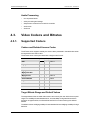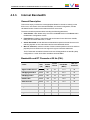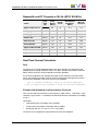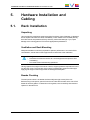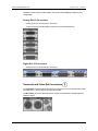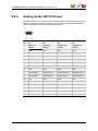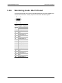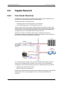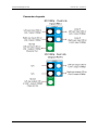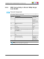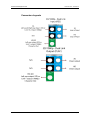
1
HARDWARE TECHNICAL
REFERENCE MANUAL
Version 14.00 - June 2015
HARDWARE TECHNICAL REFERENCE MANUAL XTnano Server 14.00
Disclaimer
This manual and the information contained herein are the sole property of EVS Broadcast
Equipment SA and/or its affiliates (EVS) and are provided “as is” without any expressed or
implied warranties, including, but not limited to, the implied warranties of merchantability
and fitness for a particular purpose. In particular, EVS makes no warranty regarding the
use or the consequences of use of this manual and the information contained herein.
Furthermore, EVS may not be held liable for any direct or indirect, incidental, punitive or
consequential loss, damage, cost or expense of any kind whatsoever and howsoever
resulting from the normal or abnormal use of this manual and the information contained
herein, even if advised of the possibility of such loss, damage, cost or expense.
While every effort has been made to ensure that the information contained in this manual
is accurate, up-to-date and reliable, EVS cannot be held liable for inaccuracies or errors
that may appear in this publication. The information in this manual is furnished for
informational purpose and use only and subject to change without notice.
This manual cancels and replaces any previous versions thereof.
Copyright
Copyright © 2010-2015 EVS Broadcast Equipment SA. All rights reserved.
This manual may not be reproduced, transcribed, stored (in a database or an retrieval
system), translated into any language, computer language, transmitted in any form or by
any means – electronically, mechanically, printed, photocopied, optically, manually or
otherwise – in whole or in part without the prior written consent of EVS.
Trademarks
All product and brand names are registered trademarks and trademarks of EVS or of their
respective owners.
Improvement Requests
Your comments will help us improve the quality of the user documentation. Please send
improvement requests, or report any error or inaccuracy on this user manual by e-mail to
[email protected].
Regional Contacts
You will find the full list of addresses and phone numbers on the following webpage:
http://www.evs.com/contacts.
I
EVS Broadcast Equipment SA
Issue 14.00.A - June 2015
User Manuals on EVS Website
The latest version of the user manual, if any, and other user manuals on EVS products can
be found on the EVS download center, on the following webpage:
http://www.evs.com/downloadcenter.
II
HARDWARE TECHNICAL REFERENCE MANUAL XTnano Server 14.00
Table of Contents
TABLE OF CONTENTS
III
WHAT'S NEW?
V
1.
1
OVERVIEW
1.1. Presentation
1
2.
2
SAFETY AND COMPLIANCE
2.1. Safety
2
2.2. EMC Standards
2
2.3. EMC Warning
3
2.4. FCC Marking
4
2.5. CE Marking
4
3.
5
HARDWARE SPECIFICATIONS
3.1. Mechanical Dimensions and Weights
3.1.1. Rack Mount 4U Main Frame
5
3.1.2. Control Devices
7
3.2. Power Supply
8
3.3. Environmental Conditions
9
4.
SOFTWARE SPECIFICATIONS
10
4.1. Video Specifications
10
4.2. Audio Specifications
11
4.3. Video Codecs and Bitrates
12
4.3.1. Supported Codecs
12
4.3.2. Maximum Bitrates
14
4.3.3. Internal Bandwidth
15
4.3.4. Recording Capacities
18
4.4. Network Transfers
5.
19
4.4.1. Gigabit Ethernet Transfers
19
4.4.2. XFile3 Capacities
22
4.5. Video Interpolation
HARDWARE INSTALLATION AND CABLING
25
27
5.1. Rack Installation
27
5.2. Rear Panel Description
28
5.2.1. Rear Panel Configurations
Table of Contents
5
28
III
EVS Broadcast Equipment SA
Issue 14.00.A - June 2015
5.2.2. 4U Rear Panel Layout
5.3. Video Connections
32
5.4. Audio Connections
32
5.4.1. Audio Channels
32
5.4.2. Digital Audio DA-15 Pinout
34
5.4.3. Analog Audio DA-15 Pinout
35
5.4.4. Monitoring Audio DA-15 Pinout
36
5.5. RS422 Connections
5.5.1. RS422 Connector Pinout
5.6. Gigabit Network
6.
37
37
38
5.6.1. Functional Overview
38
5.6.2. Important Rules
39
5.6.3. Switches
39
5.7. GPIO Connections
41
5.7.1. GP In Connections
41
5.7.2. GP Out Connections
43
BOARDS DESCRIPTION
45
6.1. Boards and Slots Configuration
45
6.2. V3X Video and Reference Boards
46
6.2.1. Description
46
6.2.2. COD Connectivity in SD and HD
49
6.2.3. COD Connectivity in 3D and 1080p Dual Link
53
6.2.4. COD Connectivity in 3D and 1080p Single Link 3G-SDI
55
6.2.5. Channel Assignment
57
6.3. Audio Codec Board
58
6.4. Controller Boards
59
6.4.1. H3X Board
59
6.4.2. H3XP Board
60
6.5. RAID Controller Boards
6.5.1. RSAS Board on SAS Disk Array
6.6. MTPC Board
IV
28
63
63
64
Table of Contents
HARDWARE TECHNICAL REFERENCE MANUAL XTnano Server 14.00
What's New?
In the Technical Reference manual, the icon
has been added on the left margin to
highlight information on new and updated features.
The changes linked to new features in version 14.00 are listed below:
New H3XP controller board
•
See section "H3XP Board" on page 60
New A3X audio board
•
See section "Audio Codec Board" on page 58
1080p Support on XTnano
•
See section "Presentation" on page 1
•
See section "XFile3 Capacities" on page 22
•
See section "COD Connectivity in 3D and 1080p Dual Link" on page 53
•
See section "COD Connectivity in 3D and 1080p Single Link 3G-SDI" on page 55
The following changes unrelated to new features for release 14.00 have been brought to
this technical reference manual. They are not highlighted with the New icon:
Updated Section on Rear Panel
•
See section "4U Rear Panel Layout" on page 28
Updated List of GbE Switches
•
See section "Switches" on page 39
Updated Data on Gigabit Ethernet Transfers
•
What's New?
See section "Gigabit Ethernet Transfers" on page 19
V
HARDWARE TECHNICAL REFERENCE MANUAL XTnano Server 14.00
1.
Overview
1.1.
Presentation
Welcome to the EVS range of products and thank you for using an EVS XTnano server.
We will do our best to satisfy your video production needs and we look forward to
continuing working with you.
The EVS XTnano servers are full digital in PAL (625i), NTSC (525i), 720p, 1080i, and
1080p standards. These multi-channel, disk-based video servers are ideal for a wide range
of broadcast applications, from sports and live production to playout and transmission.
The XTnano servers are 6 or 4-channel HD/SD slow motion replay servers from EVS.
Optimized for multiple applications, such as ingestion of audio/video files, live feed
recording, live slow motion and super motion, clipping and playlist playout control, XTnano
servers offer a flexible configuration.
They natively support a wide range of HD Intra codecs, such as Mjpeg, Avid DNxHD®,
VC-3, Apple ProRes®, MPEG-2 intra, Panasonic DVCPRO HD, AVC-Intra Class 100, as
well as SD Intra codecs. The XTnano server can be purchased with a single codec
license.
With its GbE networking capabilities, A/V files can be played and simultaneously
transferred to other EVS servers, as well as all standard NLE and archive systems.
1. Overview
1
EVS Broadcast Equipment SA
Issue 14.00.A - June 2015
2.
Safety and Compliance
2.1.
Safety
This equipment has been designed and tested to meet the requirements of the following:
•
EN 60950 (European): Safety of information technology equipment including business
equipment.
•
IEC 950 (International): Safety of information technology equipment including
business equipment.
In addition, this equipment has been designed to meet the following:
•
2.2.
UL 1950 - USA (USA): Safety of information technology equipment including business
equipment.
EMC Standards
This equipment complies with following EMC standards:
2
Standard
Area
Title
EN 55022
European
Emission Standard
EN 61000-3-2
European
Electromagnetic Compatibility (EMC) Part 3 (Limits);
Section2 ; limits for harmonic current emissions
(equipment input current <16A per phase)
EN 61000-3-3
European
European Electromagnetic Compatibility (EMC) Part 3
(Limits), Section 3; limitation of voltage fluctuation and
flicker in low-voltage supply systems for equipment with
rated current of 16 A.
EN 61000-4-3
European
European Electromagnetic Compatibility (EMC) Part 4
(Limits), Section 3; Testing and measurement techniques
- Radiated, radio-Frequency, electromagnetic field
immunity test.
EN 61000-4-4
European
European Electromagnetic Compatibility (EMC) Part 4
(Limits), Section 4; Testing and measurement techniques
- Electrical fast transient/burst immunity test.
EN 61000-4-5
European
European Electromagnetic Compatibility (EMC) Part 4
(Limits), Section 5; Testing and measurement techniques
- Surge immunity test.
EN 61000-4-6
European
European Electromagnetic Compatibility (EMC) Part 4
(Limits); Section 6 ; Testing and measurement techniques
- Immunity to conducted disturbances, induced by radiofrequency fields.
2. Safety and Compliance
HARDWARE TECHNICAL REFERENCE MANUAL XTnano Server 14.00
2.3.
Standard
Area
Title
EN 61000-4-7
European
European Electromagnetic Compatibility (EMC) Part 4
(Limits), Section 7; harmonics and interharmonics
measurements and instrumentation, for power supply
systems and equipment connected thereto.
EN 61000-4-11 European
European Electromagnetic Compatibility (EMC) Part 4
(Limits); Section 11 ; Voltage dips, short interruptions and
voltage variations immunity tests.
EN 50082-1
European
European Generic Immunity Standard – Part 1: Domestic,
commercial and light industry environment.
FCC
USA
Conducted and radiated emission limits for a Class A
digital device, pursuant to the Code of Federal
Regulations (CFR) Title 47 –
Telecommunications, Part 15: Radio Frequency devices,
subpart B-Unintentional Radiators.
EMC Warning
Changes or modifications not expressly approved by the manufacturer for compliance
could void the user's authority to operate the equipment.
This equipment generates, uses and can radiate radio frequency energy and, if not
installed and used in accordance with the instructions, may cause harmful interference to
radio communications. However, there is no guarantee that interference will not occur in a
particular installation.
If this equipment does cause harmful interference to radio or television reception, which
can be determined by turning the equipment off and on, the user is encouraged to try to
correct the interference by one or more of the following measures:
•
Reorient or relocate the receiving antenna.
•
Increase the separation between the equipment and receiver.
•
Connect the equipment into an outlet on a circuit different from that to which the
receiver is connected.
•
Consult the dealer or an experienced radio/TV technician for help.
2. Safety and Compliance
3
EVS Broadcast Equipment SA
2.4.
Issue 14.00.A - June 2015
FCC Marking
This equipment has been tested and found to comply with the limits for a Class B digital
device, pursuant to Part 15 of the FCC Rules. These limits are designed to provide
reasonable protection against harmful interference in a residential installation.
The following labels are affixed on the equipment:
2.5.
CE Marking
The CE marking is affixed to indicate compliance with the following directives:
4
•
89/336//EEC of 3 May 1989 on the approximation of the laws of the Members States
to electromagnetic compatibility.
•
73/23/EEC of 19 February 1973 on the harmonization of the laws of the Members
States relating to electrical equipment designed for use within certain voltage limits.
•
1999/5/EC of 9 March 1999 on radio equipment and telecommunications terminal
equipment and the mutual recognition of their conformity.
2. Safety and Compliance
HARDWARE TECHNICAL REFERENCE MANUAL XTnano Server 14.00
3.
Hardware Specifications
3.1.
Mechanical Dimensions and Weights
3.1.1.
Rack Mount 4U Main Frame
Weight
4U - 19 inches chassis with 6 HDD on RSAS board: 31 kg / 68.3 lb.
Dimensions
The following drawings provide the various dimensions, in mm, of the XTnano server with
a 4U chassis.
Front View
Left View
3. Hardware Specifications
5
EVS Broadcast Equipment SA
Issue 14.00.A - June 2015
Right View
Back View
6
3. Hardware Specifications
HARDWARE TECHNICAL REFERENCE MANUAL XTnano Server 14.00
3.1.2.
Control Devices
The following control devices can optionally be connected to your server to control it.
Nano Remote Control Panel
Weight: 3.4 kg / 7.5 lb.
Keyboard
Weight: 0.4 kg / 0.9 lb.
Tablet
Weight: 0.3 kg / 0.66 lb. (Ref: Wacom® CTF-430 Bamboo One)
3. Hardware Specifications
7
EVS Broadcast Equipment SA
3.2.
Issue 14.00.A - June 2015
Power Supply
Redundant Power Supply
The server is fitted with two auto switching and hot-swappable power supplies.
The secondary hot-swappable power supply should be connected to the mains to allow
automatic power switching to this second power supply should the first one fail.
Grounding
Warning
The protective earth must be connected to the ground before powering up the
unit.
Ensure the disk recorder unit is properly grounded at all times to avoid electrical
shock hazard.
Electrical Specifications
Rated voltage: 115 to 240 VAC (single phase)
Rated frequency: 47-63 Hz
Input connector: CEE 22/IEC 320 3-pin male receptacle
Connection to supply: Pluggable equipment Type A (EN 60950 §1.2.5): Equipment which
is intended for connection to the building power supply wiring via a non-industrial plug and
socket-outlet or a non-industrial appliance coupler or both. Correct mains polarity must
always be observed. Do not use reversible power plugs with this equipment.
Class of equipment: Class 1 equipment (EN 60950 § 1.2.5): electric shock protection by
basic insulation and protective earth.
Electrical Consumption
The following electrical specifications are valid for the XTnano server:
8
Data Type
Voltage
Value
Inrush current (PSU plugged on power grid)
230 V
3.0 A
Maximal current (full load, CPU at 100% )
230 V
1.3 A
Inrush current (PSU plugged on power grid)
115 V
6.3 A
Maximal current (full load, CPU at 100% )
115 V
2.8 A
Maximal power consumption (full load, CPU at 100%)
-
300 W
3. Hardware Specifications
HARDWARE TECHNICAL REFERENCE MANUAL XTnano Server 14.00
3.3.
Environmental Conditions
Operating
•
Temperature: 10°C to + 45°C (50°F to 113°F) ambient with free air flow
•
Relative humidity: 0% to 90% (non-condensing)
•
Cooling requirements: Forced cooling air flow from right to left when looking at the
EVS server from the back panel.
•
Handling/movement: Designed for fixed use when in operation
Storage and Transport
•
Temperature: 0°C to +70°C (32°F to 158°F)
•
Relative humidity: 0% to 90% (non-condensing)
3. Hardware Specifications
9
EVS Broadcast Equipment SA
Issue 14.00.A - June 2015
4.
Software Specifications
4.1.
Video Specifications
Video Standards
The following table lists the video specifications both in SD and in HD format for your
XTnano server.
Standard Definition
High Definition
Video Formats
525i 29.97fps (NTSC)
625i 25fps (PAL)
720p 50/59.94fps
1080i 50/59.94fps
Digital Interface
10-bit 4:2:2 Serial
(ST 259:2008).
Full frame synchronizer at
input.
10-bit 4:2:2 Serial (ST 2921:2011).
Full frame synchronizer at
input.
Number of Channels
4 or 6* channels,
reversible REC/PLAY
4 or 6* channels,
reversible REC/PLAY
Monitoring & Downconverters
1 SD SDI per channel, with
OSD
1 HD SDI output per channel,
with OSD
Reference
Analog Black Burst
Analog Black Burst and HD
Tri-Level Sync
Graphics Board
n.a.
n.a.
* From a hardware point of view,four codec modules, remain available on the backplane.
However, it is possible to increase the number of connected record channels by
connecting distinct recorders or players to the primary and the secondary connectors of a
codec module.
Such configurations, available with the XREC license code (30), are described in the
Configuration manual, Supported Configurations chapter.
10
4. Software Specifications
HARDWARE TECHNICAL REFERENCE MANUAL XTnano Server 14.00
SMPTE Standards
The following table lists the SMPTE standards supported by your server.
4.2.
Configuration
SMPTE standard
SD SDI
ST 259:2008 (525i 59.94 Hz; 625i 50 Hz)
HD SDI
ST 292-1:2011, ST 292:2012
(720p 50 and 59.94 Hz; 1080i 50 and 59.94 Hz)
Embedded audio HD
ST 299-0:2010, ST 299-1:2009
AES/EBU audio
ST 272:2004
LTC
ST 12-1:2008, ST12-2:2008
D-VITC
ST 266:2012
Ancillary TC in HD
RP 188
Vertical Ancillary Data
ST 334:2000
VC-3
ST 2019-1:2008
Dual Link 1.5 Gb/s
ST 372:2011
Mapping of Audio Metadata into
Vertical Ancillary data
ST 2020-2:2008, ST 2020-3:2008
Audio Specifications
Audio Analog and Digital Configurations
The following optional audio configuration is available:
•
Configuration DA-15 AES/EBU + DA-15 Analog:
◦
16 input and 16 output (8 pairs + 8 pairs) AES/EBU or Dolby E on 4 DA-15
connectors
◦
8 input and 8 output analog balanced channels on 4 DA-15 connectors
Additional Audio Specifications
•
4 additional analog balanced output channels for monitoring
•
All audio connectors on mainframe
•
Up to 64 embedded audio channels (4*16 audio mono channels per video channel) in
4-channel configurations.
•
Up to 48 embedded audio channels (6*8 audi mono channels per video channel) in 6channel configurations.
4. Software Specifications
11
EVS Broadcast Equipment SA
Issue 14.00.A - June 2015
Audio Processing
•
Uncompressed audio
•
24 bit processing and storage
•
Sample rate converter from 25-55 kHz to 48 kHz
•
Audio scrub
•
Audio mix
4.3.
Video Codecs and Bitrates
4.3.1.
Supported Codecs
Codecs and Related License Codes
The XTnano server supports natively the video codecs presented in the table below when
the required license code is valid.
The XTnano server can be purchased with a single codec license.
Codec
SD
HD
Code Protection
IMX
√
-
Code 11
Mjpeg SD
√
-
Code 10
DVCPro 50
√
-
Code 9
Mjpeg Standard HD
Mjpeg EVS HD
-
√
Code 10
Mpeg-2 Intra
-
√
Code 12
Avid DNxHD®
-
√
Code 5
Apple ProRes 422
-
√
Code 6
DVCPro HD
-
√
Code 8
AVC-Intra
-
√
Code 13
Target Bitrate Range and Default Values
The target bitrate of the encoded video stream can be set by the user within the accepted
range: 8 to 100 Mbps for standard definition, 40 to 250 Mbps for high definition with the
exception of Apple ProRes, Avid DNxHD® and DVCPro codecs working with defined
bitrates.
The default values are Mjpeg 30 Mbps for standard definition and Mjpeg 100 Mbps for high
definition.
12
4. Software Specifications
HARDWARE TECHNICAL REFERENCE MANUAL XTnano Server 14.00
Content Transfer Encoding and File Header
It is possible to perform the encoding process in 8-bit or 10-bit and to write a 10-bit file on
selected codecs.
The following table summarizes the proposed configurations, valid for encoding and file
header:
Codec
Encoding & File Header
DNxHD 120/145
8-bit
DNxHD 185/220
8-bit
DNxHD 185x/220x
10-bit
ProRes LT
10-bit
ProRes SQ
10-bit
ProRes HQ
10-bit
DVCPro HD
8-bit
Mjpeg
8-bit
Mpeg-2 Intra
8-bit
AVC-Intra 100
4. Software Specifications
10-bit
13
EVS Broadcast Equipment SA
4.3.2.
Issue 14.00.A - June 2015
Maximum Bitrates
These maximum values are valid for XTnano servers running Multicam version 12.02 or
higher. They guarantee a smooth play and a browse at 100% speed on all channels
simultaneously.
Codec
Format
2 ch
4 ch
4ch
(3D)
4ch
(3D SLSM
3x)
6 ch
SD Mjpeg
PAL
100
100
N/A
N/A
100
NTSC
100
100
N/A
N/A
100
PAL
225
225
180
100
180
NTSC
250
250
180
100
180
PAL
225
225
180
N/A
180
NTSC
250
250
180
N/A
180
PAL
185
185
185
100
185
NTSC
220
220
220
100
220
185
185
185
85
185
220
220
220
102
220
PAL
50
50
N/A
N/A
50
NTSC
50
50
N/A
N/A
50
PAL
100
100
100
N/A
100
NTSC
100
100
100
N/A
100
PAL
111
111
110
N/A
111
NTSC
111
111
110
N/A
111
HD Mjpeg
HD Mpeg-2 Intra
Avid DNxHD®
Apple ProRes 422 PAL
NTSC
DVCPro 50
DVCPro HD
AVC-Intra 100
* This value can be achieved with internal SAS HDD disks with revision 10K.5.
14
4. Software Specifications
HARDWARE TECHNICAL REFERENCE MANUAL XTnano Server 14.00
4.3.3.
Internal Bandwidth
General Description
This section helps you select the most appropriate bitrate for the native codec(s) on the
EVS server, on the basis of the internal bandwidth, the channel configuration, and the
calculated number of real-time channels at the EVS server level.
The section therefore presents tables including the following parameters:
1. Video Bitrate: codec bitrate set by the user in the Codec section of the Server tab in
the Multicam Configuration window.
2. Fields/Block: numbers of video fields that can be stored in one disk block of 8 MB,
taking into account 8 audio track, in 1080i.
3. Actual Bandwidth: actual disk/network bandwidth required for the real-time record or
real-time playback of one video stream and its associated audio tracks.
4. Max. RT Channels: maximum number of video channels (real-time record or real-time
playback) that one EVS server can support for a given frame rate and bitrate.
The RT Channels calculation is based on the use of Seagate disks of 300 GB (10K5)
configured in 4+1 raids. Such disks are able to write 400 MB/s.
Bandwidth and RT Channels at 50 Hz (PAL)
Codec
Field
Rate
(Hz)
Video
Bitrate
(Mbps)
Fields/
Block
Block-based
bandwidth
(MB/s)
Max. RT
Channels
Apple ProRes 422 LT
50.00
85
35
11.4
35
HD Mjpeg Standard
50.00
100
12
33.3
12
HD Mpeg-2 Intra
50.00
100
12
33.3
12
DVCPro HD
50.00
100
31
12.9
31
AVC Intra 100
50.00
111
30
13.3
30
Avid DNxHD® 120
50.00
120
27
14.8
27
Apple ProRes 422 SQ
50.00
120
24
16.6
24
Avid DNxHD® 185
50.00
185
18
22.2
18
Apple ProRes 422 HQ
50.00
185
16
25.0
16
4. Software Specifications
15
EVS Broadcast Equipment SA
Issue 14.00.A - June 2015
Bandwidth and RT Channels at 150 Hz (PAL SLSM 3x)
Codec
Field
Rate
(Hz)
Video
Bitrate
(Mbps)
Fields/
Block
Block-based
bandwidth
(MB/s)
Max. RT
Channels
Apple ProRes 422 LT
150.00
85
12
34.3
11.6
HD Mjpeg Standard
150.00
100
4
100.0
4.0
HD Mpeg-2 Intra
150.00
100
4
100.0
4.0
DVCPro HD
150.00
100
10
38.7
10.3
AVC Intra 100
150.00
111
10
40.0
10.0
Avid DNxHD® 120
150.00
120
9
44.4
9.0
Apple ProRes 422 SQ
150.00
120
8
50.0
8.0
Avid DNxHD® 185
150.00
185
6
66.6
6.0
Apple ProRes 422 HQ
150.00
185
5
75.0
5.3
Bandwidth and RT Channels at 59.94 Hz (NTSC)
16
Codec
Field
Rate
(Hz)
Video
Bitrate
(Mbps)
Fields/
Block
Block-based
bandwidth
(MB/s)
Max. RT
Channels
Apple ProRes 422 LT
59.94
85
35
13.7
29.2
HD Mjpeg Standard
59.94
100
14
34.2
11.6
HD Mpeg-2 Intra
59.94
100
14
34.2
11.6
DVCPro HD
59.94
100
35
13.7
29.7
AVC Intra 100
59.94
111
36
13.3
30.3
Avid DNxHD® 145
59.94
145
27
17.7
22.5
Apple ProRes 422 SQ
59.94
145
24
20.0
20.0
Avid DNxHD® 220
59.94
220
18
26.6
15.0
Apple ProRes 422 HQ
59.94
220
16
30.0
13.3
4. Software Specifications
HARDWARE TECHNICAL REFERENCE MANUAL XTnano Server 14.00
Bandwidth and RT Channels at 180 Hz (NTSC SLSM 3x)
Field
Rate
(Hz)
Video
Bitrate
(Mbps)
Fields/
Block
Block-based
bandwidth
(MB/s)
Max. RT
Channels
Apple ProRes 422 LT
179.82
85
12
41.1
9.7
HD Mjpeg Standard
179.82
100
5
102.7
3.9
HD Mpeg-2 Intra
179.82
100
5
102.7
3.9
DVCPro HD
179.82
100
12
41.1
9.7
AVC Intra 100
179.82
111
12
40.0
10.0
Avid DNxHD®
179.82
145
9
53.3
7.5
Apple ProRes 422 SQ
179.82
145
8
60.0
6.6
Avid DNxHD®
179.82
220
6
80.0
5.0
Apple ProRes 422 HQ
179.82
220
5
90.0
4.4
Codec
Real-Time Channel Calculation
Rule
The maximum server bandwidth depends on the disks. Based on the assumption that
Seagate disks of 300 GB (10K5) are used in 4+1 raids, the disks will be able to write 400
MB/s, and the maximum server bandwidth is therefore 400 MB/s.
For a mixed configuration with standard and super motion channels on the same EVS
server, the following calculation must be used to ensure that the settings do not exceed
the maximum bandwidth of the server, that is to say 400 MB/s:
(nbr of standard channels x their block-based bandwidth)
+ (nbr of super motion channels x their block-based bandwidth)
Example with Standard and Supermotion Channels
Can I run an XTnano server with 2 record channels (1 super motion + 1 standard) + 2 play
channels (1 super motion + 1 standard) in Avid DNxHD® with a video bitrate of 120 Mbps
in PAL ?
Calculation:
•
1 standard rec/play at 120 Mbps uses 14.8 MB/s
•
1 super motion record/play at 120 Mbps uses 44.4 MB/s
•
All channels will use: 2 x 14.8 + 2 x 44.4 = 118.4 MB/s.
Conclusion: this configuration is supported as it is lower than 400 MB/s.
4. Software Specifications
17
EVS Broadcast Equipment SA
4.3.4.
Issue 14.00.A - June 2015
Recording Capacities
Disk Storage
The maximum internal disk storage available on SAS disks, is as follows:
•
6 (5+1) x 300 GB SAS disks
RAID Level: 3
The video RAID uses striping process across 5 or 6 disk drives. The video and audio data
is striped over the first 4 or 5 drives while the parity information is saved on the fifth or
sixth drive.
If one drive is damaged, the video RAID can use the parity information to recover the
missing information, so that operation can continue seamlessly without bandwidth loss.
Recording Capacity Figures
The following table shows the recording capacity, in hours:
•
for 1 record channel, that is 1 video + 4 stereo audio tracks in SD; 1 video + 8 stereo
audio tracks in HD
•
with the Operational Disk Size parameter set to 100%.
•
for 4+1 (5 disks) and 5+1 (6 disks) raid configurations without spare disk, in 50.00 Hz
and 59.95Hz.
#
Disk
size
(GB)
#
Usable
disks
30Mbps
4
audios
4
audios
4
audios
8
audios
8
audios
8
audios
8
audios
5
300
4
75
58
48
23
22
19
13
6
300
5
94
73
60
29
27
20
14
#
Disks
18
40Mbps 50Mbps 100Mbps 110Mbps 120Mbps 185Mbps
4. Software Specifications
HARDWARE TECHNICAL REFERENCE MANUAL XTnano Server 14.00
4.4.
Network Transfers
4.4.1.
Gigabit Ethernet Transfers
General Description
This section provides empirical figures on real-time transfers for backup and restore jobs
processed by the GbE network. The GbE bandwidth however relies on the customer
network behavior, which depends on external conditions, and partly on the EVS servers.
Warning
The observations and data focus on steady rates: the transfer performances
with small clips will be lower as they generate a lot of starts and ends of
sessions.
The section presents data in tables including the following parameters:
1. Field Rate: field frequency used, or number of video fields transferred per second.
2. Video Bitrate: codec bitrate set by the user in the Codec section of the Server tab in
the Multicam Configuration window.
3. RT Transfers: maximum number of simultaneous transfers of A/V data that can be
processed for the given frame rate and video bitrate through the GbE network.
Calculation formula: Maximum GbE bandwidth / actual block-based
bandwidth = real-time transfers
4. Transfer Speed: transfer speed for a single transfer expressed in faster than-real time
speed. The calculation formula is the same with a reference GbE bandwidth that is
slightly smaller.
Reference Bandwidth
The table below specifies the reference GbE bandwidth used for calculations in this
section. However, the effective bandwidth depends on network behavior, which only
partly relies on the EVS server.
Real-Time Transfers
Single Transfer Speed
Backup
Restore
Backup
Restore
90 MB/s
70 MB/s
80 MB/s
70 MB/s
Gigabit Connection Type
1GbE (10GbE board)
4. Software Specifications
19
EVS Broadcast Equipment SA
Issue 14.00.A - June 2015
Backup Transfers
1GbE Connection
The maximum transfer speed through one 1GbE port of the 10GbE board on an XTnano
server in 1080i, are summarized in the following table:
20
Video
Bitrate
(Mbps)
BlockBased
Bandwidth
(MB/s)
Transfer Speed
(faster than RT)
Codec
Field
Rate
Apple ProRes 422 LT
50.00 Hz
85
11.4
7.8x
HD Mjpeg Standard
50.00 Hz
100
33.3
2.7x
HD Mpeg-2 Intra
50.00 Hz
100
33.3
2.7x
DVCPro HD
50.00 Hz
100
12.9
6.9x
AVC Intra 100
50.00 Hz
111
13.3
6.7x
Avid DNxHD® 120
50.00 Hz
120
14.8
6.1x
Apple ProRes 422 SQ
50.00 Hz
120
16.6
5.4x
Avid DNxHD® 185
50.00 Hz
185
22.2
4.0x
Apple ProRes 422 HQ
50.00 Hz
185
25.0
3.6x
4. Software Specifications
HARDWARE TECHNICAL REFERENCE MANUAL XTnano Server 14.00
Restore Transfers
1GbE Connection
The maximum transfer speed through one 1GbE port of the 10GbE board on an XTnano
server in 1080i, are summarized in the following table:
Video
Bitrate
(Mbps)
BlockBased
Bandwidth
(MB/s)
Transfer Speed
(faster than RT)
Codec
Field
Rate
Apple ProRes 422 LT
50.00 Hz
85
11.4
6.1x
HD Mjpeg Standard
50.00 Hz
100
33.3
2.1x
HD Mpeg-2 Intra
50.00 Hz
100
33.3
2.1x
DVCPro HD
50.00 Hz
100
12.9
5.4x
AVC Intra 100
50.00 Hz
111
13.3
5.2x
Avid DNxHD® 120
50.00 Hz
120
14.8
4.7x
Apple ProRes 422 SQ
50.00 Hz
120
16.6
4.2x
Avid DNxHD® 185
50.00 Hz
185
22.2
3.1x
Apple ProRes 422 HQ
50.00 Hz
185
25.0
2.8x
Simultaneous Backup and Restore
The backup sessions reach higher bandwidth and pre-empt the bandwidth against the
restore sessions. On a ‘per session’ base, the system allocates between 3.75 and 6 times
more bandwidth to backup session than to restore session.
4. Software Specifications
21
EVS Broadcast Equipment SA
4.4.2.
Issue 14.00.A - June 2015
XFile3 Capacities
Storage Capacity for 720p / 1080i at 50 Hz (PAL)
The following tables gives the time (in hours and minutes) of A/V content of a given codec
that can be stored on the XFile3 hardware for 720 and 1080i video at a frame rate of 50 Hz:
Fields/
Block
1 TB
2 TB
Apple ProRes 422 LT
35
25:29
50:58
HD Mjpeg Standard
12
8:44
17:29
HD Mpeg-2 Intra
12
8:44
17:29
DVCPro HD
31
22:34
45:08
AVC Intra 100
30
21:51
43:42
Avid DNxHD® 120
27
19:40
39:19
Apple ProRes 422 SQ
24
17:29
34:58
Avid DNxHD® 185
18
13:07
26:13
Apple ProRes 422 HQ
16
11:39
23:18
Codec
Storage Capacity for 720p / 1080i at 150 Hz (PAL Super
Motion 3x)
The following tables gives the time (in hours and minutes) of A/V content of a given codec
that can be stored on the XFile3 hardware for 720 and 1080i video at a frame rate of 150
Hz:
Fields/
Block
1 TB
2 TB
12
8:30
16:59
HD Mjpeg Standard
4
2:55
5:50
HD Mpeg-2 Intra
4
2:55
5:50
DVCPro HD
10
7:31
15:03
AVC Intra 100
10
7:17
14:34
Avid DNxHD® 120
9
6:33
13:07
Apple ProRes 422 SQ
8
5:50
11:39
Avid DNxHD® 185
6
4:22
8:44
Apple ProRes 422 HQ
5
3:53
7:46
Codec
Apple ProRes 422 LT
22
4. Software Specifications
HARDWARE TECHNICAL REFERENCE MANUAL XTnano Server 14.00
Storage Capacity for 720p / 1080i at 59.94 Hz (NTSC)
The following tables gives the time (in hours and minutes) of A/V content of a given codec
that can be stored on the XFile3 hardware for 720 and 1080i video at a frame rate of 59.94
Hz:
Fields/
Block
1 TB
2 TB
Apple ProRes 422 LT
35
21:14
42:29
HD Mjpeg Standard
14
8:30
17:00
HD Mpeg-2 Intra
14
8:30
17:00
DVCPro HD
35
21:14
42:29
AVC Intra 100
36
21:51
43:42
Avid DNxHD® 120
27
16:23
32:46
Apple ProRes 422 SQ
24
14:34
29:07
Avid DNxHD® 185
18
10:55
21:50
Apple ProRes 422 HQ
16
9:43
19:25
Codec
Storage Capacity for 720p / 1080i at 180 Hz (NTSC Super
Motion 3x)
The following tables gives the time (in hours and minutes) of A/V content of a given codec
that can be stored on the XFile3 hardware for 720 and 1080i video at a frame rate of 180
Hz:
Fields/
Block
1 TB
2 TB
12
7:05
14:10
HD Mjpeg Standard
5
2:50
5:40
HD Mpeg-2 Intra
5
2:50
5:40
DVCPro HD
12
7:05
14:10
AVC Intra 100
12
7:17
14:34
Avid DNxHD® 120
9
5:28
10:55
Apple ProRes 422 SQ
8
4:50
9:43
Avid DNxHD® 185
6
3:38
7:17
Apple ProRes 422 HQ
5
3:14
6:28
Codec
Apple ProRes 422 LT
4. Software Specifications
23
EVS Broadcast Equipment SA
Issue 14.00.A - June 2015
Storage Capacity for 1080p at 50 Hz (PAL)
The following tables gives the time (in hours and minutes) of A/V content of a given codec
that can be stored on the XFile3 hardware for 1080p video at a frame rate of 50 Hz:
Fields/
Block
1 TB
2 TB
AVC Intra 100
15
10:55
21:50
Avid DNxHD® 240
13
9:28
18:56
Apple ProRes 422 LT
18
13:07
26:13
Apple ProRes 422 SQ
12
10:24
20:48
Apple ProRes 422 HQ
8
5:50
11:40
Codec
Storage Capacity for 1080p at 59.94 Hz (NTSC)
The following tables gives the time (in hours and minutes) of A/V content of a given codec
that can be stored on the XFile3 hardware for 1080p video at a frame rate of 59.94 Hz:
Fields/
Block
1 TB
2 TB
AVC Intra 100
18
10:55
21:50
Avid DNxHD® 365
14
8:30
17:00
Apple ProRes 422 LT
18
10:55
21:50
Apple ProRes 422 SQ
12
7:17
14:34
Apple ProRes 422 HQ
8
4:50
9:41
Codec
24
4. Software Specifications
HARDWARE TECHNICAL REFERENCE MANUAL XTnano Server 14.00
4.5.
Video Interpolation
Introduction
The playing back of smooth slow motion pictures carries specific issues: since some
fields must be repeated at regular interval to provide the video at the playback speed
required by the operator, parity violation appears regularly on the output video signal. This
issue is specific to interlaced formats (525i, 625i and 1080i) and does not concern
progressive formats (720p).
If O and E represent respectively the odd and even fields of a standard video signal
(50/60 Hz), we have:
The original video signal:
◦
OEOEOEOEOEOEOEOE
The output video signal at 50% speed:
◦
OOEEOOEEOOEEOOEE
The output video signal at 33% speed:
◦
OOOEEEOOOEEEOOOE
The output video signal at 25% speed :
◦
OOOOEEEEOOOOEEEE
Fields with parity violation are shown in bold, underlined letters. As it appears from the
above table, whatever the playback speed (with the exception of the normal 100%
playback speed), a number of fields violate the normal parity of the output signal. This
parity violation induces a 1-line shift of the field, resulting in a vertical jitter of the picture.
The jitter frequency depends upon the chosen playback speed.
To avoid this phenomenon and provide a stable output picture, EVS developed 2 types of
line interpolator: 2-line and 4-line interpolators. The interpolation process can be enabled or
disabled by the operator on all EVS slow motion systems.
2-Line Interpolator
The 2-line interpolator actually generates a new field, when the original field is in parity
violation. Each line of this new field is calculated by a weighted average of the 2
neighboring lines. This process solves the problem of parity violation and vertical jitter, but
the drawback is a reduction of the vertical resolution on the interpolated fields, that appear
unfocused. Another side effect is the alternation of original fields (perfectly focused) and
interpolated fields (unfocused), resulting in a "pumping" video signal.
4. Software Specifications
25
EVS Broadcast Equipment SA
Issue 14.00.A - June 2015
4-Line Interpolator
The 4-line interpolator uses a more sophisticated calculation based on the 4 neighboring
lines. By using suitable coefficients for the weight of each line in the resulting calculation,
we apply this interpolation to all fields. The final result is a permanently, slightly unfocused
picture. The advantage is a stable output signal with no jitter and no "pumping", but the
vertical bandwidth is even more reduced.
The interpolator is of course always disabled at 100% playback speed, because there is
no parity violation.
EVS uses the same techniques with the Super Slow Motion disk recorder, working with all
models of Super Motion cameras (150/180 Hz). The only difference between the
processing of Super Motion and normal scan (50/60 Hz) signals is that the interpolator is
always disabled at 33% playback speed, because the Super Motion signal does not cause
parity violation at this particular speed.
Whatever the choice, the resulting picture is thus always a compromise between stability
and resolution. With EVS systems, the operator always has the choice between any of
the 3 above described techniques: no interpolation, 2-line interpolation or 4-line
interpolation. Even if the operator chooses to use the interpolation, this process will be
automatically disabled when not necessary (100% playback for 50/60 Hz signal, 33% and
100% playback for 150/180 Hz signal).
Note
All professional VTRs use line interpolation in PlayVar mode to avoid vertical
jitters.
Default value is interpolator off for all configurations except SLSM configurations
in which 4-line interpolator mode is enabled.
26
4. Software Specifications
HARDWARE TECHNICAL REFERENCE MANUAL XTnano Server 14.00
5.
Hardware Installation and
Cabling
5.1.
Rack Installation
Unpacking
Upon receipt of the equipment examine packing for obvious signs of damage. If damaged,
do not unpack and inform the carrier immediately. Check thanks to the included packing
list if all the items are present and if they show any mechanical damage. If yes, report
damage or the missing parts to EVS or their appropriate representative.
Ventilation and Rack Mounting
Adequate ventilation is obviously required for optimum performance. As a result of this
consideration, ensure that no other equipment is located close to the mainframe.
Warning
• Remember that fans are used to air cool the equipment and protect it from
overheating.
• Do not block fans intakes during operations.
Having regard to the weight of the server chassis, support guides are required for this unit
into the rack mount. The front ears of the unit are not designed to support its full weight.
Applying full weight on these might result in bending the metal plate.
Boards Checking
The main power switch is located at the front side (lower right corner) of the unit.
Before turning on the power, open the front door of Video disk recorder unit to check if all
boards fit into their guides. If a board is out of its guides, remove carefully the board and
replace it in the same slot.
5. Hardware Installation and Cabling
27
EVS Broadcast Equipment SA
5.2.
Rear Panel Description
5.2.1.
Rear Panel Configurations
Issue 14.00.A - June 2015
The XTnano server is available in 4U rack:
•
5.2.2.
with 4 or 2 codec modules and various audio connectors.
4U Rear Panel Layout
Rear Panel Areas
The following drawing represents an example of a 4U rear panel available on an XTnano
server.
The various areas of the rear panel are highlighted in the drawing and their respective
variants are listed in the sections below along with a short description of the related
connectors.
28
5. Hardware Installation and Cabling
HARDWARE TECHNICAL REFERENCE MANUAL XTnano Server 14.00
Video and Codecs
The codecs modules allow connections for recording and playback of video material. Each
connector on a codec module is connected to the corresponding J connector on the COD
A or COD B module of a V3X board.
See section "V3X Video and Reference Boards" on page 46 for more details on each
connector specific usage according to the different configurations.
The following video and codecs connectors layouts are available according to your
configuration:
Config
Layout
Description
222
444
Analog and Digital Audio
This section shows the available associations of audio connectors.
See section "Audio Specifications" on page 11 for more details on the available audio
configurations.
See section "Audio Connections" on page 32 for more details on the DA-15 connectors
pinout according to the different configurations.
5. Hardware Installation and Cabling
29
EVS Broadcast Equipment SA
Issue 14.00.A - June 2015
The audio connector layouts described in this section are available according to your
configuration:
Analog DA-15 Connectors
•
4 multi-pin DA-15 connectors (2 in and 2 out)
•
1 multi-pin DA-15 for audio output connection for monitoring purposes
Digital DA-15 Connectors
•
4 multi-pin DA-15 connectors (2 in and 2 out)
Timecode and Video Ref Connectors
The Timecode connectors allow the server to receive the LTC timecode reference signal
and send the LTC timecode that corresponds to PGM1.
The Ref Video connectors allow the server to receive or send back the analog genlock
reference signal.
30
5. Hardware Installation and Cabling
HARDWARE TECHNICAL REFERENCE MANUAL XTnano Server 14.00
Controls and Communications
This rear panel part, located below the audio connectors, presents connectors that allow
the EVS server to communicate with other devices. The connectors are described from
top left to bottom right:
The RS422 ports allow the server to be remotely controlled through remote panels or
third-party control devices. When a remote panel is used, it should be connected on the
first RS422 port.
Two PC LAN connectors allow connection of the PC LAN interface of the EVS server to
an Ethernet network.
The Console connectors allow a monitor and a keyboard to be connected to the server.
Controls and Communications
This rear panel part, located on the right of the codec connectors, presents connectors
that allow the EVS server to communicate with other devices. The connectors are
described from top left to bottom right:
The Loop connector allows the loop of PGM1 on REC1 to be able to use the internal loop
feature.
The Multiviewer connectors allow two monitors to be connected directly to the server,
and to display PGM and REC channels as configured in the Multicam Configuration
window, in the Monitoring tab, Multiviewer page. See the Multicam Configuration manual
for a description of the configuration parameters.
The GPI connector allows GPI (General Purpose Interface) devices to send or receive
electric pulses that will trigger commands on the server or to be connected with third-party
devices.
5. Hardware Installation and Cabling
31
EVS Broadcast Equipment SA
Issue 14.00.A - June 2015
Gigabit Ethernet Connector Module
The Gigabit Ethernet Connector module is located at the bottom center of the rear panel.
This area can have one of the following layouts:
•
It hosts a light version of the Gigabit connector module:
The Gigabit Ethernet connector module allows the interconnection of servers, other
EVS, and/or third-party systems into a Gigabit Ethernet network via:
◦
2 RJ45 connectors, each offering a global bandwidth of 1 GbE
◦
SD card slot
Power Supplies
The server power supply is made of two hot-swappable units. Both of these units are
connected to allow automatic power switching to the second power supply should the first
one fail.
5.3.
Video Connections
You fill find full details on video connections in the Configuration manual, in the chapter
"Supported Configurations".
5.4.
Audio Connections
5.4.1.
Audio Channels
The XTnano server server manages up to 192 64 audio channels, depending on the
chosen variant and the installed hardware.
The embedded audio modules and codecs can be used as input or output channels for
embedded, digital (AES/EBU), or analog audio signals.
32
5. Hardware Installation and Cabling
HARDWARE TECHNICAL REFERENCE MANUAL XTnano Server 14.00
Depending on the server chassis or configuration, you can find the following audio
connectors on the rear panel:
•
Digital audio:
◦
•
Analog audio:
◦
•
DA-15 connectors: 8 inputs (high-balanced) and 8 outputs (600 Ohm drive
capable).
Audio monitoring :
◦
•
DA-15 connectors: 16 inputs (8 pairs) and 16 outputs (8 pairs) (110 Ohm
balanced).
DA-15 connector: 4 analog mono outputs (600 Ohm drive capable) .
Breakout cables with XLR connectors can be adapted on DA-15 connectors.
See also section "Audio Specifications" on page 11 for full information on the available
audio hardware configurations.
The connectors are illustrated along with their respective pinouts in the following topics.
5. Hardware Installation and Cabling
33
EVS Broadcast Equipment SA
5.4.2.
Issue 14.00.A - June 2015
Digital Audio DA-15 Pinout
The digital audio DA-15 connector is illustrated hereunder (connector installed on the rear
panel and viewed from outside). Its pinout is described in the following table where each
column corresponds to one of the 4 available connectors.
34
Pin
#
DA-15 connector
#1
Inputs 1-8
(mono)
DA-15 connector
#2
Inputs 9-16
(mono)
DA-15 connector
#3
Outputs 1-8
(mono)
DA-15 connector
#4
Outputs 9-16
(mono)
1
Gnd
Gnd
Gnd
Gnd
2
AES input 1/2 +
AES input 9/10 +
AES output 1/2 +
AES output 9/10 +
3
Gnd
Gnd
Gnd
Gnd
4
AES input 3/4 +
AES input 11/12 +
AES output 3/4 +
AES output 11/12
+
5
Gnd
Gnd
Gnd
Gnd
6
AES input 5/6 +
AES input 13/14 +
AES output 5/6 +
AES output 13/14
+
7
Gnd
Gnd
Gnd
Gnd
8
AES input 7/8 +
AES input 15/16 +
AES output 7/8 +
AES output 15/16
+
9
AES input 1/2 -
AES input 9/10 -
AES output 1/2 -
AES output 9/10 -
10
Gnd
Gnd
Gnd
Gnd
11
AES input 3/4 -
AES input 11/12 -
AES output 3/4 -
AES output 11/12 -
12
Gnd
Gnd
Gnd
Gnd
13
AES input 5/6 -
AES input 13/14 -
AES output 5/6 -
AES output 13/14 -
14
Gnd
Gnd
Gnd
Gnd
15
AES input 7/8 -
AES input 15/16 -
AES output 7/8 -
AES output 15/16 -
5. Hardware Installation and Cabling
HARDWARE TECHNICAL REFERENCE MANUAL XTnano Server 14.00
5.4.3.
Analog Audio DA-15 Pinout
The analog audio DA-15 connector is illustrated hereunder (connector installed on the rear
panel and viewed from outside). Its pinout is described in the following table where each
column corresponds to one of the 4 available connectors.
Pin
#
DA-15 connector
#1
Inputs 1-4
(mono)
DA-15 connector
#2
Inputs 5-8
(mono)
DA-15 connector
#3
Outputs 1-4
(mono)
DA-15 connector
#4
Outputs 5-8
(mono)
1
Gnd
Gnd
Gnd
Gnd
2
Analog input 1 +
Analog input 5 +
Analog output 1 +
Analog output 5 +
3
Gnd
Gnd
Gnd
Gnd
4
Analog input 2 +
Analog input 6 +
Analog output 2 +
Analog output 6 +
5
Gnd
Gnd
Gnd
Gnd
6
Analog input 3 +
Analog input 7 +
Analog output 3 +
Analog output 7 +
7
Gnd
Gnd
Gnd
Gnd
8
Analog input 4 +
Analog input 8 +
Analog output 4 +
Analog output 8 +
9
Analog input 1 -
Analog input 5 -
Analog output 1 -
Analog output 5 -
10
Gnd
Gnd
Gnd
Gnd
11
Analog input 2 -
Analog input 6 -
Analog output 2 -
Analog output 6 -
12
Gnd
Gnd
Gnd
Gnd
13
Analog input 3 -
Analog input 7 -
Analog output 3 -
Analog output 7 -
14
Gnd
Gnd
Gnd
Gnd
15
Analog input 4 -
Analog input 8 -
Analog output 4 -
Analog output 8 -
5. Hardware Installation and Cabling
35
EVS Broadcast Equipment SA
5.4.4.
Issue 14.00.A - June 2015
Monitoring Audio DA-15 Pinout
The monitoring audio DA-15 connector is illustrated hereunder (connector installed on the
rear panel and viewed from outside). Its pinout is described in the following table.
36
Pin #
DA-15 connector
Outputs 1-4 (mono)
1
Gnd
2
Analog output 1 +
3
Gnd
4
Analog output 2 +
5
Gnd
6
Analog output 3 +
7
Gnd
8
Analog output 4 +
9
Analog output 1 -
10
Gnd
11
Analog output 2 -
12
Gnd
13
Analog output 3 -
14
Gnd
15
Analog output 4 -
5. Hardware Installation and Cabling
HARDWARE TECHNICAL REFERENCE MANUAL XTnano Server 14.00
5.5.
RS422 Connections
5.5.1.
RS422 Connector Pinout
The RS422 connectors are used to connect a remote control (from EVS or third party) to
your server.
The cable wiring is a straightforward pin-to-pin connection as illustrated in the following
diagram. You should use a shielded cable to avoid electromagnetic interference on long
distances.
Warning
The RESET command line from the remote control is sent through the pin 5 of
the RS422 connector. This function should be disabled when the controller on
connector #1 is not an EVS controller.
The technical specification for the RS422 link is as follows:
◦
19200 bauds
◦
No parity
◦
8 data bits
◦
1 stop bit
5. Hardware Installation and Cabling
37
EVS Broadcast Equipment SA
5.6.
Gigabit Network
5.6.1.
Functional Overview
Issue 14.00.A - June 2015
The Gigabit connection makes it possible to transfer video and audio material from your
XTnano server to external systems via the TCP/IP network.
The external systems can be the following:
•
A storage system or an archiving system, such as XStore.
•
A non-linear editing system, such as Apple Final Cut Pro.
However, the external systems cannot read the raw files coming from a XTnano server.
For this reason, XTAccess is used as a “gateway” between your server and the IT world.
In this architecture, the Xsquare application plays the role of XTAccess orchestrator on
the Gigabit network, communicating via the PC LAN connection.
Moreover, the XTnano is not able to directly send commands to the XTAccess.
Consequently, a backup tool called Xtract is used as the interface to send commands to
the XTAccess for file transfer operations and wrapping.
XT Access is directly connected to the XTnano servers through the Gigabit network. It
runs on an XP workstation and is controlled, in this context, by Xtract via XML files.
The Gigabit connection fulfills the following functions in relation with the XTnano server:
•
Backup of clips from an XTnano server.
•
Restore of clips to an XTnano server.
Please refer to the Xtract user manual for more information on the backup from and restore
of clips to the XTnano, using the Gigabit network, in combination with Xtract and
XTAccess.
38
5. Hardware Installation and Cabling
HARDWARE TECHNICAL REFERENCE MANUAL XTnano Server 14.00
5.6.2.
Important Rules
Gigabit networks including EVS servers need to abide by the following rules:
•
The hardware used on GbE networks with EVS servers need to support jumbo frames.
•
Both GbE ports of an EVS server need to be defined on different sub-networks.
•
Teaming between the GbE1 and GbE2 ports is not possible.
•
This is not possible to implement failover through the GbE network.
•
The GbE port available on the MTPC board (PC LAN) is a 100Base-T port.
This is used for monitoring purposes (XNet Monitor) or for the communication with
other applications (LinX). This can be in the same sub-network as the GbE port.
5.6.3.
Switches
1GbE Switches
All switches used on the GbE networks of EVS systems need to support jumbo frames
(Ethernet frames with more than 1,500 bytes of payload).
The following table gives an overview on the supported 1GbE switches:
Jumbo
Frames
Dual
PSU
2 10G SFP+ or Yes
2 1G SFP
Switching
No
48 10/100/1000
Base-T
2 10G SFP+ or Yes
2 1G SFP
Switching
No
Cisco WS-2960S-24TS-L
24 10/100/1000
Base-T
4 1G SFP
Yes
Switching
No
Cisco WS-2960S-48TS-L
48 10/100/1000
Base-T
4 1G SFP
Yes
Switching
No
Cisco WS-3850X-24T-S
24 10/100/1000
Base-T
Module
Yes
Routing
Opt.
Cisco WS-3850X-48T-S
48 10/100/1000
Base-T
Module
Yes
Routing
Opt.
Arista 7048T-A
48 10/100/1000
Base-T
4 10G SFP+
No
Routing
Yes
Type
Ports
Uplinks
Cisco WS-2960S-24TD-L
24 10/100/1000
Base-T
Cisco WS-2960S-48TD-L
5. Hardware Installation and Cabling
Stackable
39
EVS Broadcast Equipment SA
Issue 14.00.A - June 2015
Optional Modules for the Cisco WS-3850X
Product Number
Description
C3850-NM-4-1G
4 Gigabit Ethernet SFP
C3850-NM-2-10G
4 Gigabit Ethernet SFP / 2 10 Gigabit Ethernet SFP+
C3850-NM-4-10G
4 Gigabit Ethernet SFP / 4 10 Gigabit Ethernet SFP+
Remark: 4x10 Gigabit uplinks are only possible with the 48-port version, the 24-port
version only supports 2x10GbE uplinks.
Recommendations
The models Cisco Catalyst 2960S-24TS and 2960S-48TS can be used for small setups
where no inter-VLAN routing is needed and no 10G uplinks.
The models Cisco Catalyst 2960S-24TD and 2960S-48TD can be used for small setups
where 10G uplinks are required, but no inter-VLAN routing is needed.
On larger setups, both GbE ports of the XTnano servers or/and several ports on the SANs
are often used to increase the bandwidth or to allow redundancy. Since both GbE ports of
an XTnano server cannot be used on the same sub-network, virtual LANs need to be
created. To allow the transfer of packets between the virtual LANs, layer 3 switches are
required. You need to select a layer 3 switch that is able to route jumbo frames. The Cisco
Catalyst 3850X series does support jumbo frames, allows traffic to be routed between
different VLANs and provides stacking capabilities.
Recommended SFP+ Modules
XTnano server TGE Module
•
Intel® Ethernet SFP+ SR Optic (E10GSFPSR)
•
Intel® Ethernet SFP+ LR Optic (E10GSFPLR)
Those modules are tested to be compatible with the TGE interface board of the XTnano
server and the 10 Gbps SFP+ NICs equipped in some EVS servers.
Switches
On the switches it is recommended to use the modules recommended by the switch
vendors.
40
5. Hardware Installation and Cabling
HARDWARE TECHNICAL REFERENCE MANUAL XTnano Server 14.00
5.7.
GPIO Connections
5.7.1.
GP In Connections
GPI Triggers
The allocation of the XTnano server GPI triggers is performed in the Multicam
Configuration window, in the GPI tab. See the Configuration manual for detailed
information on allocating GPI triggers.
Opto isolated Inputs (GP In 1, 2, 3, 4)
Pin-Out
Specifications
•
The input consists in an opto diode (VF @ 1.1 Volt) in series with a 470 ohm resistor.
•
Typical switching point @ 1.4 mA, for secure operation:
•
◦
i=0 to 0.5 mA -> opto OFF
◦
i=2.5 to 30 mA -> opto ON
◦
imax= 30 mA
Direct connection to a TTL/CMOS signal possible (Pin opto - to GND and pin opto + to
the TTL/CMOS signal).
Typical switching point @ 1.6 Volts, for secure operation:
◦
Vin< 0.8 Volts -> opto OFF
◦
Vin> 2.2 Volts @ 2 mA -> opto ON
◦
Vin max (without external resistor) = 15 Volts
5. Hardware Installation and Cabling
41
EVS Broadcast Equipment SA
Issue 14.00.A - June 2015
TTL Inputs (GP In 5, 6, 7, 8)
Relay Inputs Pin-Out
The relay must be connected between the ground and the corresponding TTL input on the
DB-25.
TTL Inputs Pin-Out
Each TTL input on the DB-25 is directly connected to the pin of the TTL connector on the
device triggering the GPI. The ground must be common between the DB-25 connector of
the XTnano server and the external device.
Specifications
42
•
each pin can be individually configured as an output or an input
•
internal 4K7 pull up to +5 V
•
low level Vi < 1.5 Volt (U12 = 74HC245)
•
high level Vi > 3.5 Volt (U12 = 74HC245)
•
optional TTL compatible level (U12 = 74HCT245)
5. Hardware Installation and Cabling
HARDWARE TECHNICAL REFERENCE MANUAL XTnano Server 14.00
5.7.2.
GP Out Connections
Relay Isolated Outputs (GP Out 1, 2, 3, 4)
Pin-Out
The user can define the functions, types and settings associated to the GPI outs in the
following applications:
•
Setup menu of the Remote Panel
•
IP Director settings (GPI and Auxiliary Track tab)
Specifications
•
normally open contact (power off -> open)
•
maximum 1 A
•
maximum 50 Volts
•
typical life time: 100.000.000 switchings
TTL Outputs (GP Out 5, 6, 7, 8)
Pin-Out
5. Hardware Installation and Cabling
43
EVS Broadcast Equipment SA
Issue 14.00.A - June 2015
Specifications
44
•
each pin can be individually configured as an output or an input
•
internal 4K7 pull up to +5 V
•
low level Vi < 1.5 Volt (U12 = 74HC245)
•
high level Vi > 3.5 Volt (U12 = 74HC245)
•
optional TTL compatible level (U12 = 74HCT245)
5. Hardware Installation and Cabling
HARDWARE TECHNICAL REFERENCE MANUAL XTnano Server 14.00
6.
Boards Description
6.1.
Boards and Slots Configuration
The XTnano server is equipped with several boards that are all developed by EVS.
According to your server version, the following setup configurations are available:
4U Rack
Installed boards
Slot #
4 video channels
6
RSAS
5
H3X or H3XP
4
CODA or A3X (Audio Codec)
3
V3X (SD/HD) #2
—
2
V3X (SD/HD) #1 Genlock
V3X (SD/HD) #1 Genlock
1
6. Boards Description
2 video channels
MTPC
45
EVS Broadcast Equipment SA
Issue 14.00.A - June 2015
6.2.
V3X Video and Reference Boards
6.2.1.
Description
Overview
The V3X board is divided in several parts:
•
a base board identified as V3X base (rear section and center extension)
•
two modules identified as COD A V3X (front left) and COD B V3X (front right)
Warning
It is highly advised not to remove a V3X board from your EVS server. Should you
have to do so, manipulate the board very carefully, making sure it is not exposed
to mechanical or electric shocks.
COD Modules
The COD A V3X and COD B V3X modules are the actual codec modules, each of them
being able to be configured by software either as an encoder (for a record channel) or as a
decoder (for a play channel). The COD V3X modules are SD, HD.
They support the following feature(s):
•
Full resolution 3D HD on a single V3X module (Dual Link HD SDI)
Genlock
There are 2 versions of the V3X board: one with genlock, one without genlock.
The genlock model can easily be identified by the presence of 3 quartz synthesizers at the
rear of the V3X base board, on the right-hand side, and by the presence of the GLK and
PSU OK LEDs on either side of the DIN connector at the center front of the board.
Note that a V3X board with genlock must be installed as V3X #1 in first position (slot 2) in
the server. A V3X board with genlock can never be installed in any other slot, and thus
cannot be used instead of V3X #2. Doing so will result in conflicting electrical signals
inside the system.
Block Diagram
The block diagram of the V3X board with genlock is illustrated hereunder with the
connectors, jumpers and LEDs location:
46
6. Boards Description
HARDWARE TECHNICAL REFERENCE MANUAL XTnano Server 14.00
Base Board Jumpers
The following table lists the V3X base board jumpers and their respective function:
Jumper
Function
ST1, ST2
These 2 jumpers must be installed on the last V3X board of the server
(that is on V3X #1, 2 if there are respectively 1, 2 V3X boards installed in
the server).
ST3 (SPARE)
«Parking» for ST1 and ST2 jumpers when they are not used.
ST4 (only
on V3X
with
genlock)
Must be set to HiZ (or not installed).
Note that the Genlock Loop connector on the back panel of the server (if
available) must always be terminated with a 75 Ohm load if it is not used.
ST5
Defines the position of the board inside the server. It must be set to « 1 »
for a V3X with genlock, and to « 2 » for a V3X board without genlock,
depending on its position in the server.
6. Boards Description
47
EVS Broadcast Equipment SA
Issue 14.00.A - June 2015
Base Board LEDs
The table below lists the LEDs available on the V3X base board with the genlock
functionality.
Warning
It is crucial to have a continuous and stable genlock signal when the server is in
operation. In case of interferences on the genlock signal that would cause parity
violations, the recorders will automatically be restarted to maintain data
integrity.
LED
GLK
Color Status
—
Off
Green
Blinking
The genlock module is properly initialized, but no valid
genlock signal is detected.
On
The module is initialized and a valid genlock signal is
detected.
Red
PSU
OK
48
Function
Blinking
The genlock module is not initialized.
There is a genlock problem.
On
A resync is needed.
Green
On
All voltages are present and in the allowed range.
—
Off
There is a voltage problem.
6. Boards Description
HARDWARE TECHNICAL REFERENCE MANUAL XTnano Server 14.00
V3X COD Modules LEDs
The following table lists the LEDs available on then V3X COD modules (from left to right):
LED
Color Status
CPU
Green Blinking Indicates CPU activity.
PLAY
Green
Function
On
There is a problem with the module processor.
On
The module is set in play mode by the software.
Off
The module is set in record mode.
On
A valid video signal has been detected on the J8
connector (SD/HD SDI input), whether the module is in
play or record mode.
PVID
Green
TF (transfer)
Green Blinking Data transfers occur between the module and the H3X
board.
M1
—
—
Not used.
M2
M3
M4
6.2.2.
COD Connectivity in SD and HD
Connector Assignments
This section describes the connector assignments and layout for the video standards SD
525i, SD 625i, HD 1080i and HD 720p.
The specific connectivity for HD 3D Dual Link is described in the following sections.
Connector SD mode
HD mode
Connector
label
J1
Not used
Not used
CHAR SD
J2
SDI monitoring output (SD)
SDI monitoring output
(HD)
Not wired
to the
backplane.
Used for
onboard
multiviewer
input.
J3
Loop-through for the SDI
input signal (SD)
Loop-through for the SDI
input signal
(SD, down-converted)
OUT B
6. Boards Description
49
EVS Broadcast Equipment SA
Issue 14.00.A - June 2015
Connector
label
Connector SD mode
HD mode
J4
SDI monitoring output (SD)
SDI monitoring output
(SD/HD)
J5
Not used
or
SDI input (SD) in an XREC
configuration
Not used
IN B
or
SDI input (HD) in an XREC
configuration
J6
SDI program output
HD SDI program output
OUT
J7
Not used
Not used
OUT
J8
SDI input (SD)
HD SDI input (HD)
IN
J9
Alternate SDI input
(SD, for the internal loop)
Alternate HD SDI input
(HD, for the internal loop)
Not wired
to the
backplane.
J9 of
REC1 only
connected
to Loop
connector.
CHAR
OUT
SD/HD
Note
The loops of the input signal are not genlocked.
50
6. Boards Description
HARDWARE TECHNICAL REFERENCE MANUAL XTnano Server 14.00
Connector Layouts
6. Boards Description
51
EVS Broadcast Equipment SA
52
Issue 14.00.A - June 2015
6. Boards Description
HARDWARE TECHNICAL REFERENCE MANUAL XTnano Server 14.00
6.2.3.
COD Connectivity in 3D and 1080p Dual Link
Connector Assignments
This section describes the connector assignments and layout for the video standards HD
3D and 1080p in Dual Link mode.
Connector 3D/1080p mode
Connector label
J1
Not used
CHAR SD
J2
SDI monitoring output (HD)
Not wired to the backplane.
Used for onboard multiviewer
input
J3
HD SDI program output for right eye
(3D) or link 2 (1080p)
(HD)
OUT B
J4
SDI monitoring output for left eye (3D)
or link 1 (1080p)
(HD/SD)
CHAR OUT SD/HD
J5
HD SDI input for right eye (3D) or link 2
(1080p)
(HD)
IN B
J6
HD SDI program output for left eye (3D) OUT
or link 1 (1080p)
J7
Not used
OUT
J8
HD SDI input for left eye (3D) or link 1
(1080p)
(HD)
IN
J9
Alternate HD SDI input
(HD, for the internal loop)
Not wired to the backplane.
J9 of REC1 only connected to
Loop connector.
Note
The loops of the input signal are not genlocked.
6. Boards Description
53
EVS Broadcast Equipment SA
Issue 14.00.A - June 2015
Connectors Layouts
54
6. Boards Description
HARDWARE TECHNICAL REFERENCE MANUAL XTnano Server 14.00
6.2.4.
COD Connectivity in 3D and 1080p Single
Link 3G-SDI
Connector Assignments
This section describes the connector assignments and layout for the video standards HD
3D and 1080p in Single Link 3G-SDI mode.
Connector 3D/1080p Mode
Connector label
J1
Not used
CHAR SD
J2
SDI program output 2D (HD)
Not wired to the
backplane.
Used for onboard
multiviewer input
J3
SDI program output 2D
(HD)
OUT B
J4
SDI monitoring output for left eye (3D) or link 1 (1080p) CHAR OUT
(HD/SD)
SD/HD
J5
Not installed
J6
3G-SDI program output for left & right eyes (3D) or link OUT
1 & 2 (1080p)
(3G, identical to J7)
J7
Not used
J8
3G-SDI input left & right eyes (3D) or link 1 & 2 (1080p) IN
(3G)
J9
Alternate 3G-SDI input
(3G, for the internal loop)
IN B
OUT
Not wired to the
backplane.
J9 of REC1 only
connected to
Loop connector.
Note
The loops of the input signal are not genlocked.
6. Boards Description
55
EVS Broadcast Equipment SA
Issue 14.00.A - June 2015
Connectors Layouts
56
6. Boards Description
HARDWARE TECHNICAL REFERENCE MANUAL XTnano Server 14.00
6.2.5.
Channel Assignment
Server with Two Codec Boards
The following table shows how the channels (play or record channels) are assigned to the
codec boards and connectors:
Codec Board
Codec Connector
Channel Number
Lower codec board (slot 2)
COD A
CAM D or PGM 1
Lower codec board (slot 2)
COD B
CAM C or PGM 2
Middle codec board (slot 3)
COD A
CAM B or PGM 3
Middle codec board (slot 3)
COD B
CAM A or PGM 4
Server with a Single Codec Board
The following table shows how the channels (play or record channels) are assigned to the
codec board and connectors:
Codec Board
Codec Connector
Channel Number
Lower codec board (slot 2)
COD A
CAM B or PGM 1
Lower codec board (slot 2)
COD B
CAM A or PGM 2
6. Boards Description
57
EVS Broadcast Equipment SA
6.3.
Issue 14.00.A - June 2015
Audio Codec Board
The audio codec board (A3X) is the audio interface between the V3X boards and the
H3X/H3XP board. Video codec and audio codec boards are tied to the H3X/H3XP board
with one bus connector on the front side. Different audio configurations are available with
the audio codec board. See section "Audio Connections" on page 32 for details.
The following LEDs are available on the audio codec board:
58
•
LED 1-3: internal EVS information only.
•
LED 4: transfer activity to/from the H3X/H3XP board.
6. Boards Description
HARDWARE TECHNICAL REFERENCE MANUAL XTnano Server 14.00
6.4.
Controller Boards
6.4.1.
H3X Board
The H3X board is divided in 4 parts (2 in front, 2 in the back).
•
Front left: GbE module.
•
Front right: CTL controller module.
•
Back left: CPU module.
•
Back right: not installed (SDTI).
6. Boards Description
59
EVS Broadcast Equipment SA
Issue 14.00.A - June 2015
LEDs Function
The available LEDs linked to SDTI controller module are, from left to right:
LED
Color
Status
Function
LED 1
Green
On
Ok.
Red
On
An error occurred while booting the H3X board.
LED 2 to
LED 8
—
—
For EVS internal use only.
FRAMER
Green
On
Not used.
NET
Green
On
Not used.
DSP
Green
Blinking
Indicates DSP activity (audio processing).
The available LEDs linked to the CPU module are, from left to right:
LED
Color Status
CPU1
CPU2
Green Blinking These LEDs blink alternately every 250 milliseconds to
indicate that the processor is running.
Other
LEDs
—
—
Function
For EVS internal use only.
Gigabit Connectors
The two board Gigabit connectors are connected to the two backplane Gigabit ports.
The Gigabit connectors must be on a network that supports Jumbo Frames of (at least)
9014 bytes Ethernet frames. See section "Switches" on page 39 for the list of supported
switches.
You can set up the GbE IP addresses in the Multicam Configuration window, in the
Network tab, Gigabit Ethernet section.See the Configuration manual for more information.
6.4.2.
H3XP Board
The H3XP board is divided in 4 parts:
60
•
Back center: CPU module.
•
Back right: not installed (SDTI).
•
Left: not used currently
•
Front center and right: not used currently
6. Boards Description
HARDWARE TECHNICAL REFERENCE MANUAL XTnano Server 14.00
LEDs Function
The available LEDs linked to the SDTI controller module are, from left to right:
LED
Color
Status
LED 1
Green
On
Ok.
Red
On
An error occurred while booting the H3X board.
LED 2 to
LED 8
—
—
For EVS internal use only.
FRAMER
Green
On
Not used.
NET
Green
On
Not used.
DSP
Green
Blinking
6. Boards Description
Function
Indicates DSP activity (audio processing).
61
EVS Broadcast Equipment SA
Issue 14.00.A - June 2015
The available LEDs linked to the CPU module are, from left to right:
LED
Color Status
CPU1
CPU2
Green Blinking These LEDs blink alternately every 250 milliseconds to
indicate that the processor is running.
Other
LEDs
62
—
—
Function
For EVS internal use only.
6. Boards Description
HARDWARE TECHNICAL REFERENCE MANUAL XTnano Server 14.00
6.5.
RAID Controller Boards
6.5.1.
RSAS Board on SAS Disk Array
Disk Arrays on systems with H3X boards have a controller on the disk array board.
Different configurations can be used
•
One internal array with a series of 6 disks
•
No internal storage
LEDs on Internal Array
LEDs 1 to 6 are used in case of one internal array of 6 disks.
LEDs correspond to the disks as schematized as followed:
1
2
6
3
4
5
LED
Status
Function
Disk
LEDs
Off
the corresponding disk is not started (not spinning)
On, fast blinking
(green)
the corresponding disk is starting (spinning)
On, steady (green)
the corresponding disk is started and used in the RAID
array
On, slowly blinking the corresponding disk is started but not used in the
(green)
RAID array
STS
On (green)
the RSAS RAID controller is properly booted.
ERR
On (red)
errors occur during the data transfer between the RAID
controller and the disks
6. Boards Description
63
EVS Broadcast Equipment SA
6.6.
Issue 14.00.A - June 2015
MTPC Board
Introduction
The function of the PC board is mainly the control of the video hardware and the interface
of the peripheral equipment (such as a remote controller) with the video hardware.
The following MTPC board is used:
•
64
Revision A3/A6 with COMMEL HS873 motherboard and a new time code
management module (with bootable USB).
6. Boards Description
HARDWARE TECHNICAL REFERENCE MANUAL XTnano Server 14.00
In standard configuration the PC hardware is composed of:
•
One mounting PC board, with serial ports, LTC reader and generator, is controlled by
the motherboard.
•
SAS System Hard disk: the SAS disk drive is used for storing the EVS software and
the DOS operating system. Neither audio nor video data is saved on this disk. The
capacity of this drive may vary depending on market availability, but the system
partition is always set to 2 GB. The remaining capacity of this drive is not used.
•
256 MB SDRAM (or higher) to suit the system requirements from Multicam 12.00.
Please contact EVS support for RAMs upgrade. Do not use standard PC RAM
modules.
Illustration
6. Boards Description
65
EVS Broadcast Equipment SA
Issue 14.00.A - June 2015
Multiviewer
The multiviewer board is an option on XTnano servers.
Connectors Function
IN
The J2 connectors from the CODEC modules of the COHX board are
connected to the IN connectors of the multiviewer board.
OUT1
The OUT1 connector of the multiviewer board is connected to the
MULTIVIEWER 1 connector on the rear panel of the server.
OUT2
The OUT2 connector of the multiviewer board is connected to the
MULTIVIEWER 2 connector on the rear panel of the server.
DA-15
The DA-15 connector of the multiviewer board is connected to the MULTI
DA-15 connector on the rear panel of the server.
LED Information
Internal EVS information
Board Configuration
HPOL, VPOL and ENVS are used to configure the composite sync generator used in LSM
TV mode (no effect if the server is only used with a VGA monitor).
The HPOL jumper can be used to invert or not the VGA HS signal (Horizontal Sync) to
generate the composite output signal (TV mode)
The VPOL jumper can be used to invert or not the VGA VS signal (Vertical Sync) to
generate the composite output signal (TV mode)
The ENVS jumper can be used to enable or not the presence of the VGA VS signal
(Vertical Sync) in the composite output signal (TV mode)
If the LSM TV mode is used, these jumpers must be set up according to EVS
recommendations, which depend on software version and CPU board model/revision:
Set up the jumpers as follows:
•
HPOL=On; VPOL=Off; ENVS=On
REMOTE RESET jumpers are available to designate the remote(s) from which the
RESET command can be sent.
This command resets the whole system: PC and video hardware.
66
6. Boards Description
HARDWARE TECHNICAL REFERENCE MANUAL XTnano Server 14.00
In standard configuration only Remote one (on RS422 port 1) is allowed to reset the
system.
Warning
This jumper should be removed if the device connected to the RS422 port is
NOT an EVS controller. Maximum voltage on pin 5 of an RS422 port of the
server should not exceed 5 Volt when the corresponding jumper is engaged.
Applying a higher voltage on pin 5 when the corresponding jumper is engaged
will result in permanent electronic damage to the board.
6. Boards Description
67
Corporate
+32 4 361 7000
North & Latin America
+1 973 575 7811
EVS Headquarters
Liège Science Park
13, rue Bois St Jean
B-4102 Seraing
Belgium
To learn more about EVS go to www.evs.com
Asia & Pacific
+852 2914 2501
Other regional offices
www.evs.com/contact
EVS Broadcast Equipment is continuously adapting and improving its products in accordance with the ever changing
requirements of the Broadcast Industry.
The data contained herein is therefore subject to change without prior notice. Companies and product names are
trademarks or registered trademarks of their respective companies.