1
/ Instruction Manual
CC-Link Communications Card
"OPC-G1-CCL"
Fuji Electric Co., Ltd.
INR-SI47-1328d-JE
English Version
Preface
Thank you very much for purchasing our CC-Link Communications Card "OPC-G1-CCL."
This manual has been prepared to help you connect your FRENIC-MEGA to a CC-Link master (Mitsubishi
Electric PLC, etc.) via CC-Link.
Mounting this communications card on your FRENIC-MEGA allows you to connect the FRENIC-MEGA to a
CC-Link master and control it as a slave using run commands, speed commands, and access to inverter's
function codes.
The communications card can be connected to the A-port only, out of three option connection ports (A-, B-, and
C-ports) provided on the FRENIC-MEGA.
The communications card has the following features:
• CC-Link Version:
Complies with CC-Link versions 1.10 and 2.00
• Applicable Profile: Inverter (1 station occupied)
• Monitoring the status of the FRENIC-MEGA (running status, frequency, output torque, output current,
output voltage, etc.)
• Reading and writing from/to function codes applicable to the FRENIC-MEGA
Logo mark:
The communications card is a CC-Link version 2.00 compliant remote device unit and supports the following:
- Extended cyclic transmission
- Easing restrictions on inter-station cable length
This instruction manual does not contain inverter handling instructions. Read through this instruction manual in
conjunction with the FRENIC-MEGA Instruction Manual and be familiar with proper handling and operation of
this product. Improper handling might result in incorrect operation, a short life, or even a failure of this product.
Keep this manual in a safe place.
Related Publications
Listed below are the other materials related to the use of the CC-Link Communications Card "OPC-G1-CCL."
Read them in conjunction with this manual as necessary.
• RS-485 Communication User's Manual
• FRENIC-MEGA Instruction Manual
The materials are subject to change without notice. Be sure to obtain the latest editions for use.
• Read through this instruction manual and be familiar with the CC-Link communications card before
proceeding with installation, connections (wiring), operation, or maintenance and inspection.
• Improper handling might result in incorrect operation, a short life, or even a failure of this product as
well as the motor.
• Deliver this manual to the end user of this product. Keep this manual in a safe place until this product
is discarded.
1
Safety precautions
Read this manual thoroughly before proceeding with installation, connections (wiring), operation, or
maintenance and inspection. Ensure you have sound knowledge of the device and familiarize yourself with all
safety information and precautions before proceeding to operate the inverter.
Safety precautions are classified into the following two categories in this manual.
Failure to heed the information indicated by this symbol may lead to
dangerous conditions, possibly resulting in death or serious bodily
injuries.
Failure to heed the information indicated by this symbol may lead to
dangerous conditions, possibly resulting in minor or light bodily injuries
and/or substantial property damage.
Failure to heed the information contained under the CAUTION title can also result in serious consequences.
These safety precautions are of utmost importance and must be observed at all times.
Installation and wiring
• Before starting installation and wiring, turn OFF the power and wait at least five minutes for inverters
with a capacity of 22 kW or below, or at least ten minutes for inverters with a capacity of 30 kW or
above. Make sure that the LED monitor and charging lamp are turned OFF. Further, make sure,
using a multimeter or a similar instrument, that the DC link bus voltage between the terminals P(+)
and N(-) has dropped to the safe level (+25 VDC or below).
• Qualified electricians should carry out wiring.
Otherwise, electric shock could occur.
• Do not use the products that are damaged or lacking parts.
Doing so could cause a fire, accident, or injury.
• Prevent lint, paper fibers, sawdust, dust, metallic chips, or other foreign materials from getting into
the inverter and the communications card.
Otherwise, a fire or an accident might result.
• Incorrect handling in installation/removal jobs could cause a failure.
A failure might result.
• Noise may be emitted from the inverter, motor and wires. Implement appropriate measure to prevent
the nearby sensors and devices from malfunctioning due to such noise.
Otherwise, an accident could occur.
2
Operation
• Be sure to install the front cover before turning the inverter's power ON. Do not remove the cover
when the inverter power is ON.
Otherwise electric shock could occur.
• Do not operate switches with wet hands.
Doing so could cause electric shock.
• If you configure the function codes wrongly or without completely understanding FRENIC-MEGA
Instruction Manual and the FRENIC-MEGA User's Manual, the motor may rotate with a torque or at a
speed not permitted for the machine. Confirm and adjust the setting of the function codes before
running the inverter.
Otherwise, an accident could occur.
Maintenance and inspection, and parts replacement
• Before proceeding to the maintenance/inspection jobs, turn OFF the power and wait at least five
minutes for inverters with a capacity of 22 kW or below, or at least ten minutes for inverters with a
capacity of 30 kW or above. Make sure that the LED monitor and charging lamp are turned OFF.
Further, make sure, using a multimeter or a similar instrument, that the DC link bus voltage between
the terminals P(+) and N(-) has dropped to the safe level (+25 VDC or below).
Otherwise, electric shock could occur.
• Maintenance, inspection, and parts replacement should be made only by qualified persons.
• Take off the watch, rings and other metallic objects before starting work.
• Use insulated tools.
Otherwise, electric shock or injuries could occur.
Disposal
• Treat the communications card as an industrial waste when disposing of it.
Otherwise injuries could occur.
Others
• Never modify the communications card.
Doing so could cause electric shock or injuries.
Icons
The following icons are used throughout this manual.
This icon indicates information which, if not heeded, can result in the product not operating to full
efficiency, as well as information concerning incorrect operations and settings which can result in
accidents.
This icon indicates information that can prove handy when performing certain settings or operations.
This icon indicates a reference to more detailed information.
3
Table of Contents
Preface
..................................................................... 1
Chapter 8 ERROR PROCESSING FOR CC-Link
NETWORK BREAKS ....................................... 25
Safety precautions ............................................................ 2
Chapter 9 LIST OF INVERTER ALARM CODES ............. 26
Chapter 1 BEFORE USE ................................................... 5
1.1 Acceptance Inspection .......................................... 5
1.2 Applicable Inverters ............................................... 5
Chapter
2.1
2.2
2.3
Chapter
10.1
10.2
10.3
10 APPLICATION PROGRAM EXAMPLES ........ 27
System Configuration ........................................... 27
Network Parameter Settings ................................ 27
Relationship between Master Station Device
and Remote I/O and Remote Register ................. 28
10.4 CC-Link Startup Program ..................................... 29
10.5 Program Example Using the Inverter Running
Status Read ......................................................... 29
10.6 Program Example for Changing the Operation
Mode .................................................................... 30
10.7 Program Example for Specifying Run Command. 30
10.8 Program Example for Monitoring the Output
Frequency ............................................................ 31
10.9 Program Example for Reading from the
Inverter's Function Code Data ............................. 31
10.10 Program Example for Writing to Inverter's
Function Code Data ............................................. 32
10.11 Program Example for Setting up the Reference
Frequency ............................................................ 33
10.12 Program Example for Reading out Alarm Codes . 34
10.13 Program Example for Resetting a Inverter Trip .... 34
2 NAMES AND FUNCTIONS ............................... 6
External Appearance ............................................. 6
Terminating Resistor Switch (SW1) ....................... 6
LED Status Indicators ............................................ 7
Chapter 3 INSTALLATION AND REMOVAL OF THE
CC-Link COMMUNICATIONS CARD ................ 8
3.1 Installing the Communications Card ...................... 8
3.2 Removing the Communications Card .................... 9
Chapter
4.1
4.2
4.3
4 WIRING AND CABLING .................................. 10
Basic Connection Diagram .................................. 10
Wiring for CC-Link Terminal Block ........................ 11
Wiring to Inverter ................................................. 12
Chapter 5 CONFIGURING INVERTER'S FUNCTION
CODES FOR CC-Link COMMUNICATION ..... 13
Chapter 6 SETTING-UP PROCEDURE ........................... 14
Chapter
7.1
7.2
7.3
7.4
7 LIST OF I/O SIGNALS..................................... 15
Remote I/O Signals ............................................. 15
Remote Registers ................................................ 17
List of Monitor Item Codes ................................... 21
Command Codes and Response Codes ............. 23
Chapter 11 TROUBLESHOOTING ................................... 35
Chapter 12 SPECIFICATIONS ......................................... 36
12.1 General Specifications ......................................... 36
12.2 CC-Link Specifications ......................................... 36
4
Chapter 1
BEFORE USE
1.1 Acceptance Inspection
Unpack the package and check the following:
(1) A communications card, two screws (M3 8), and the CC-Link Communications Card Instruction Manual
(this manual) are contained in the package.
(2) The communications card is not damaged during transportation--no defective parts, dents or warps.
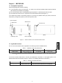
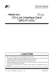
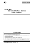
(3) The model name "OPC-G1-CCL" is printed on the communications card. (See Figure 1.1.)
If you suspect the product is not working properly or if you have any questions about your product, contact the
shop where you bought the product or your local Fuji branch office.
Screw hole (left)
Release knob
Model name
Connector CN1
(Front)
(Back)
Screw hole (right)
Positioning cutout
Figure 1.1 Names of Parts on CC-Link Communications Card
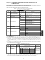
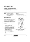
1.2 Applicable Inverters
The CC-Link communications card is applicable to the following inverters and ROM version.
Table 1.1 Applicable Inverters and ROM Version
Series
Inverter type
FRENIC-MEGA
* The boxes
FRN
G1 -
Applicable motor rating
ROM version
All capacities
0500 or later
replace alphanumeric letters depending on the nominal applied motor, enclosure, power supply voltage, etc.
To check the inverter's ROM version, use Menu #5 "Maintenance Information" on the keypad. (Refer to the
FRENIC-MEGA Instruction Manual, Chapter 3, Section 3.4.6 "Reading maintenance information.")
Table 1.2 Checking the Inverter ROM Version
Display on LED Monitor
Item
Inverter's ROM version
Description
Shows the inverter's ROM version as a 4-digit code.
5
Chapter 2
NAMES AND FUNCTIONS
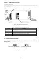
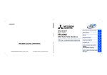
2.1 External Appearance
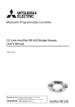
The external appearance and the components of the CC-Link communications card are shown in Figure 2.1 and
Table 2.1, respectively.
TERM1
CN1
(on the back)
LED status indicators
SW1
Figure 2.1 External View and Component Names
Table 2.1 Components on the CC-Link Communications Card
Component
TERM1
Description
CC-Link terminal block (3.5 mm pitch)
CN1
Connector for joint with inverter
SW1
Terminating resistor switch (For details, see Section 2.2.)
(ON: Insertion of terminating resistor, OFF: No insertion)
LED status indicators
RD, SD, L.ERR, RUN, and L.RUN (For details, see Section 2.3.)
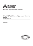
2.2 Terminating Resistor Switch (SW1)
The CC-Link communications network requires insertion of line terminating resistors at its both ends. When this
communications card is mounted on the inverter at either end of the network, turn this switch ON to insert the
terminating resistor.
ON
OFF
ON
OFF: No insertion of terminating resistor
OFF
ON: Insertion of terminating resistor
Figure 2.2 Terminating Resistor Switch Settings
6
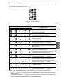
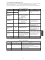
2.3 LED Status Indicators
This communications card has five LED status indicators shown below. They indicate the operation status of the
communications card as listed in Table 2.2.
Figure 2.3 LED Status Indicators
Table 2.2 LED Status Indicators and Operation Status
L.RUN
RUN
LED States
L.ERR
SD
Operation Status
RD
Normally communicating.
Normally communicating. But sometimes a CRC error
occurs due to electrical noise.
Received data contains a CRC error, so the
communications card cannot respond.
Data destined for this station does not come.
Responding to polling. But refresh data received
contains a CRC error.
The inverter trips with alarm
displayed. *1
Data destined for this station contains a CRC error.
The inverter trips with alarm
displayed. *1
Station address incorrectly specified.
Data destined for this station cannot be received due
to electrical noise.
/
Transmission speed (Baud rate) and/or station
address out of the allowable range.
Transmission speed (Baud rate) or station address
changed during CC-Link communication.
The communications card cannot receive data due to
a network break, etc.
The inverter trips with alarm
displayed. *1
The master station is compliant with CC-Link version
1.xx and this slave station, with CC-Link version 2.xx.
Or the inverter's function code o30 is set to "5 to 255."
The inverter trips with alarm
displayed.
Communications error between the communications
card and the inverter.
The inverter trips with alarm
displayed.
Communications card error.
The inverter trips with alarm
: ON,
: OFF,
displayed.
: Blinking (It may seem to be ON depending on the current transmission speed.)
*1 Alarm
occurs when a communications error is detected after a normal communications link has been
established once.
It is possible to change the
occurrence conditions with inverter's function codes. For details, refer to
Chapter 8 "ERROR PROCESSING FOR CC-Link NETWORK BREAKS."
7
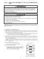
Chapter 3
INSTALLATION AND REMOVAL OF THE CC-Link COMMUNICATIONS
CARD
Before starting installation and wiring, turn OFF the power and wait at least five minutes for inverters with a
capacity of 22 kW or below, or at least ten minutes for inverters with a capacity of 30 kW or above. Make
sure that the LED monitor and charging lamp are turned OFF. Further, make sure, using a multimeter or a
similar instrument, that the DC link bus voltage between the terminals P(+) and N(-) has dropped to the
safe level (+25 VDC or below).
Otherwise, electric shock could occur.
• Do not use the products that are damaged or lacking parts.
Doing so could cause a fire, accident, or injury.
• Prevent lint, paper fibers, sawdust, dust, metallic chips, or other foreign materials from getting into the
inverter and the communications card.
Otherwise, a fire or an accident might result.
• Incorrect handling in installation/removal jobs could cause a failure.
A failure might result.
Before mounting the communications card, perform the wiring for the main circuit terminals and control
circuit terminals.
3.1 Installing the Communications Card
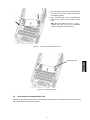
(1) Remove the front cover from the inverter and expose the control printed circuit board (control PCB). As
shown in Figure 3.1, the communications card can be connected to the A-port only, out of three option
connection ports (A-, B-, and C-ports) on the control PCB.
To remove the front cover, refer to the FRENIC-MEGA Instruction Manual, Chapter 2, Section 2.3. For
inverters with a capacity of 30 kW or above, open also the keypad enclosure.
(2) Insert connector CN1 on the back of the communications card (Figure 1.1) into the A-port (CN4) on the
inverter's control PCB. Then secure the communications card with the two screws that come with the
communications card. (Figure 3.3)
Check that the positioning cutout (shown in Figure 1.1) is fitted on the tab ( in Figure 3.2) and
connector CN1 is fully inserted ( in Figure 3.2). Figure 3.3 shows the communications card
correctly mounted.
(3) Perform wiring on the communications card.
Refer to Chapter 4 "WIRING AND CABLING."
(4) Put the front cover back into place.
To put back the front cover, refer to the
FRENIC-MEGA Instruction Manual, Chapter 2,
Section 2.3. For inverters with a capacity of 30 kW or
above, close also the keypad enclosure.
Figure 3.1 In the case of 0.4 kW
8
Fit the positioning cutout of the communications
card over the tab on the inverter to determine
the mounting position.
Insert connector CN1 on the communications
card into the A-port on the inverter's control
PCB.
Note: Be sure to follow the order of
and .
Inserting CN1 first may lead to insufficient
insertion, resulting in a contact failure.
Figure 3.2 Mounting the Communications Card
(Release knob)
Figure 3.3 Mounting Completed
3.2
Removing the Communications Card
Remove the two screws that secure the communications card and pull the release knob (shown above) to take
the communications card out of the inverter.
9
Chapter 4
WIRING AND CABLING
• Before starting installation and wiring, turn OFF the power and wait at least five minutes for inverters with
a capacity of 22 kW or below, or at least ten minutes for inverters with a capacity of 30 kW or above.
Make sure that the LED monitor and charging lamp are turned OFF. Further, make sure, using a
multimeter or a similar instrument, that the DC link bus voltage between the terminals P(+) and N(-) has
dropped to the safe level (+25 VDC or below).
• Qualified electricians should carry out wiring.
Otherwise, an electric shock could occur.
• In general, the covers of the control signal wires are not specifically designed to withstand a high voltage
(i.e., reinforced insulation is not applied). Therefore, if a control signal wire comes into direct contact with
a live conductor of the main circuit, the insulation of the cover might break down, which would expose the
signal wire to a high voltage of the main circuit. Make sure that the control signal wires will not come into
contact with live conductors of the main circuit.
Failure to observe this precaution could cause an electric shock or fire.
Noise may be emitted from the inverter, motor and wires. Take appropriate measures to prevent the nearby
sensors and devices from malfunctioning due to such noise.
An accident could occur.
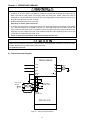
4.1 Basic Connection Diagram
FRENIC-MEGA
L1/R
U
L2/S
V
L3/T
W
G
G
FG
SLD
To CC-Link
network
Blue
White
Yellow
CC-Link cable
Terminating
resistor switch
DA
DB
DG
CC-Link
terminal block
OPC-G1-CCL
Figure 4.1 Basic Connection Diagram
10
Motor
G
4.2 Wiring for CC-Link Terminal Block
(1) To connect this communications card to a CC-Link network, use a CC-Link dedicated cable complying with
the CC-Link specifications. Using a cable other than a CC-Link dedicated cable does not assure the
CC-Link system performance. Also observe the wiring lengths specified in the CC-Link version 1.10
specifications.
The recommended CC-Link cable is FANC-110SBH made by Kuramo Electric Co., Ltd.
For details about wiring for CC-Link, refer to the CC-Link Master Use's Manual or CC-Link Cable Wiring
Manual published by the CC-Link Partner Association. The CC-Link Cable Wiring Manual is available as a
free download from the CC-Link Partner Association's website at:
http://www.cc-link.org/eng/t_html/siryo.html
(2) Wiring around the CC-Link terminal block
The terminal block uses a pluggable 5-pin connector as shown in Figure 4.2. Table 4.1 shows the
correspondence between the pin numbers and the ID colors.
A typical connector that matches this terminal block is Phoenix Contact MCVW 1.5/5-STF-3.5.
Table 4.1 Layout of Terminal Pins
ID Color of
Wire Sheath
Pin #
Name
1
DA
Blue
2
DB
White
3
DG
Yellow
4
SLD
Metallic
5
FG
Description
For communication data
For shielded wire
For grounding
Figure 4.2
Connectors on the
CC-Link Terminal Block
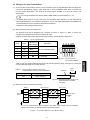
Table 4.2 lists the recommended terminal screw size and its tightening torque, and Figure 4.3 shows the
recommended strip length of the cable wire end.
Table 4.2
Recommended Tightening Torque of the
Terminal Screws on the CC-Link Terminal Block
Terminal screw size
Tightening torque
M2
0.22 to 0.25 N·m
Cable wire
Approx.
6.0 mm
Figure 4.3 Recommended Strip Length of the
Cable Wire End for Terminal
Connection
(3) When two or more inverters are connected
Terminating
resistor
Master
OPC-G1-CCL
OPC-G1-CCL
DA
DA
DA
DB
DB
DB
DG
DG
DG
SLD
FG
CC-Link cable
SLD
CC-Link cable
FG
Terminating resistor
(SW1 ON)
SLD
FG
* On CC-Link communications cards connected in the middle of the network, set their terminating
resistor switches (SW1) to OFF (No insertion of terminating resistor).
Figure 4.4 Connection Diagram of Two or More Inverters
11
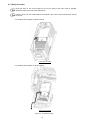
4.3 Wiring to Inverter
Route the wiring of the CC-Link cable as far from the wiring of the main circuit as possible.
Otherwise electric noise may cause malfunctions.
Pass the wires from the communications card between the control circuit terminal block and the
front cover.
• For inverters with a capacity of 22 kW or below
In the case of 0.4 kW
• For inverters with a capacity of 30 kW or above
In the case of 75 kW
Figure 4.5 Examples of Wiring
12
Chapter 5
CONFIGURING INVERTER'S FUNCTION CODES FOR CC-Link
COMMUNICATION
Before starting CC-Link communication between the inverter equipped with this communications card and the
CC-Link master device, configure the inverter's function codes listed in Table 5.1.
Table 5.2 lists other related function codes to be configured if necessary.
Table 5.1
Function
code
Inverter's Function Codes for CC-Link Communication
(The underlined values are factory defaults.)
Function
Setting range
Description
Error processing to perform when a
communications link error or a communications
card failure is detected.
o27 *1
Select error processing for
CC-Link network breaks.
0 to 15
o28 *1
Set the operation timer to be
used in error processing for
network breaks.
Specify the timer period during which the
0.0 to 60.0 sec. inverter keeps running even if a network break
is detected.
o30 *2
o31 *3
o32 *3
CC-Link extension
Station address
Transmission speed
0, 1
1 station occupied (CC-Link version 1.10)
2
1 station occupied, 2X setting
(CC-Link version 2.00)
3
1 station occupied, 4X setting
(CC-Link version 2.00)
4
1 station occupied, 8X setting
(CC-Link version 2.00)
5 to 255
No operation
1 to 64
Set a station address.
0, 65 to 255
Invalid
0
156 kbps
1
625 kbps
2
2.5 Mbps
3
5 Mbps
4
10 Mbps
5 to 255
Invalid
*1 For details about the function codes o27 and o28, refer to Chapter 8 "ERROR PROCESSING FOR CC-Link
NETWORK BREAKS."
*2 After changing the o30 data, resetting the communications card (by turning the terminal signal RST ON or by
pressing the
key on the keypad) validates the new setting. However, resetting the communications card causes
an inverter trip with an alarm
if Version 1.xx is specified on the master station and Version 2.xx on the o30
setting.
*3 Changing the o31 or o32 data causes the L.ERR LED to start blinking. Resetting the communications card validates
the new setting and turns the L.ERR LED OFF.
Table 5.2 Other Related Function Codes
Function
code
y98 *
Function
Select
run/frequency
command sources
Factory
default
0
Function code data
Select from the following choices:
Frequency
Run command
y98
command source
source
0
Inverter
Inverter
1
CC-Link
Inverter
2
Inverter
CC-Link
3
CC-Link
CC-Link
Remarks
If there is no
special problem
with your system,
setting y98 = 3 is
recommended.
* In addition to y98, there are some function codes that specify run/frequency command sources. Using those function
codes enables more flexible settings of run/frequency command sources. For details, refer to the description for the
function codes H30 and y98 in the FRENIC-MEGA Instruction Manual, Chapter 5 "FUNCTION CODES."
13
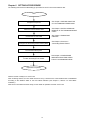
Chapter 6
SETTING-UP PROCEDURE
The following flow shows the initial setting-up procedure for the CC-Link communications card.
Start
See Chapter 1 "BEFORE USING THE
CC-Link COMMUNICATIONS CARD."
Acceptance inspection
Mount the communications card
See Chapter 3 "INSTALLATION AND
REMOVAL OF THE COMMUNICATIONS
CARD."
Connect the CC-Link cable
See Chapter 4 "WIRING AND
CABLING."
Configure the terminating resistor switch (SW1)
See Chapter 2, Section 2.2
"Terminating Resistor Switch."
Turn ON the inverter power
Configure function codes y98 and o27 to o32
to match the settings in the master
See Chapter 5 "CONFIGURING
INVERTER'S FUNCTION CODES
FOR CC-Link COMMUNICATION."
Preparation completed
Now the inverter is ready to run via CC-Link.
After confirming that the CC-Link master has been set up, check that the communications link is established
according to the ON/OFF states of the LED status indicators (see Chapter 2, Section 2.3 "LED Status
Indicators").
After the CC-Link master becomes ready, run the master to operate the inverter via CC-Link.
14
Chapter 7
LIST OF I/O SIGNALS
7.1 Remote I/O Signals
(1) Remote outputs (Master
Inverter)
Device No.
RY0
Signal name
Run forward command
RY1
Run reverse command
RY2
Terminal X1 function
RY3
Terminal X2 function
RY4
Terminal X3 function
RY5
Terminal X4 function
RY6
Terminal X5 function
RY7
Terminal X6 function
RY8
Terminal X7 function
RY9
Secondary side output
cut off (BX)
RYA
Terminal X8 function *2
RYB
Terminal X9 function *2
RYC
*3
Monitor command
RYD
*4
Frequency command /
Torque command
(RAM)
RYE
RYF
*5
RY1A
*6
Not used.
Command code
execution request
Alarm reset request flag
OFF:
ON:
OFF:
ON:
Description
Stop command
Run forward command
Stop command
Run reverse command
Terminal command assigned by inverter's
function code E01
Terminal command assigned by inverter's
function code E02
Terminal command assigned by inverter's
function code E03
Terminal command assigned by inverter's
function code E04
Terminal command assigned by inverter's
function code E05
Terminal command assigned by inverter's
function code E06
Terminal command assigned by inverter's
function code E07
ON: Coast to a stop
Remarks
Simultaneously
turning RY0 and RY1
ON is functionally
equivalent to a stop
command.
*1
*1
*1
*1
*1
*1
*1
Effective only when
the run command
source is CC-Link.
Terminal command assigned by inverter's
function code E08
*1
Terminal command assigned by inverter's
function code E09
*1
Turning this signal ON causes the inverter to store monitored values
into remote registers RWr0, 1, 4 to 7 and then turns the "Monitoring"
signal (RXC) ON.
Turning this signal ON writes the reference frequency (RWw1) /
torque command (RWwC) to the inverter's RAM. Upon completion of
writing, the "Frequency setting / Torque setting completed" signal
(RXD) is turned ON.
-Turning this signal ON executes processing corresponding to
command codes specified in RWw2, 10, 12, 14, 16, and 18. After
execution of those command codes, the "Command code execution
completed" signal (RXF) is turned ON.
If a command code execution error occurs, the error factor will be set
to the response code (RWr2, 10, 12, 14, 16, and 18).
Turning this signal ON and then OFF when a trip has occurred
resets the trip state and turns this flag (RX1A) OFF.
*1 For details about inverter's function codes E01 to E09, refer to the FRENIC-MEGA Instruction Manual,
Chapter 5 "FUNCTION CODES." Depending upon terminal commands assigned to terminals X1 through X9,
these signals may not be operated via CC-Link. For details, refer to the RS-485 Communication User's
Manual, Chapter 5, Section 5.1.2 [ 3 ] "Operation command data."
*2 These terminals are not provided in some types of the FRENIC-MEGA. For details, refer to the
FRENIC-MEGA Instruction Manual, Chapter 5 "FUNCTION CODES."
*3 While the "Monitor command" (RYC) is ON, the monitored values are constantly updated.
*4 While the "Frequency command / Torque command" (RYD) is ON, the current reference frequency (RWw1)
/ torque command (RWwC) is constantly reflected on the speed.
*5 Each time the "Command code execution request" (RYF) is turned ON, the command specified by the
command code executes once. To execute it again, it is necessary to turn the "Command code execution
request" (RYF) ON again.
*6 Turning the "Alarm reset request flag" signal (RY1A) from ON to OFF resets the alarm. Normally, this signal
should be set to OFF.
15
(2) Remote inputs (Inverter
Device No.
RX0
Master)
Signal name
Running forward
Description
OFF: Except running in forward direction (Stopped or Rotating in
reverse direction)
ON:
RX1
Running reverse
Rotating in forward direction
OFF: Except running in reverse direction (Stopped or Rotating in
forward direction)
ON:
Rotating in reverse direction
*1
RX2
Terminal Y1 function
Terminal state assigned by inverter's function code E20
RX3
Terminal Y2 function
Terminal state us assigned by inverter's function code E21 *1
RX4
Terminal Y3 function
Terminal state assigned by inverter's function code E22
*1
RX5
Terminal Y4 function
Terminal state assigned by inverter's function code E23
*1
RX6
Terminal Y5 function
Terminal state assigned by inverter's function code E24
*1
RX7
Terminal 30A/B/C
function
Terminal command assigned by inverter's function code E27 *1
RXC
Monitoring
This signal is turned ON when turning the "Monitor command" (RYC)
ON has caused the inverter to store monitored values into remote
registers RWr0, 1, 4 to 7.
Turning the "Monitor command" (RYC) OFF turns this signal OFF.
RXD
Frequency setting /
Torque setting
completed
RXE
Not used.
RXF
Command code
execution completed
This signal is turned ON when turning the "Frequency command /
Torque command" (RYD) ON has written the reference frequency /
torque command into the inverter.
Turning the "Frequency command / Torque command" (RYD) OFF
turns this signal OFF.
-This signal is turned ON when turning the "Command code execution
request" (RYF) ON has completed the execution of processing
corresponding to command codes (specified in RWw2, 10, 12, 14, 16,
and 18).
Turning the "Command execution request" (RYF) OFF turns this signal
OFF.
RX1A
Alarm state flag
This signal is turned ON when the inverter has tripped.
RX1B
Remote station
ready
This signal is turned ON when powering on the inverter or resetting the
hardware has readied the inverter. (This signal is used for interlocking
with reading or writing from/to the master unit.)
This signal is turned OFF concurrently when the "Alarm state flag"
(RX1A) is turned ON if the inverter trips.
*1 For details about inverter's function codes E20 to E24 and E27, refer to the FRENIC-MEGA Instruction
Manual, Chapter 5 "FUNCTION CODES."
16
7.2 Remote Registers
(1) Remote registers RWw (Master
Device No.
Inverter)
Signal name
Description
Remarks
RWw0
Monitor code 2/
Monitor code 1
Write the codes (listed in Table 7.1) of monitor
items to be referred to, into RWw0. After that,
turning the RYC ON stores the value of those
monitor items into RWr0 and RWr1.
The lower and upper
bytes correspond to
monitor codes 1 and
2, respectively.
RWw1
Reference
frequency /
Torque command
Write the reference frequency into RWw1. After
that, turning the RYD ON sets up that frequency
to the inverter. After completion of frequency
setting, the RXD is turned ON.
Unit: 0.01 Hz
If torque command is activated by the function
code H18, torque command is written instead of
reference frequency.
Unit: 0.01%
In detail, refer to the remarks of “RWwC”.
Effective only the
case y98=1, 3.
In case o30=3, 4 (4X
/ 8X setting of
CC-Link extension),
only frequency can
be set with RWw1.
RWw2
Command code
Write one of command codes (listed in Table 7.2)
into RWw2, which are required for execution of
the following: writing/reading of operation
methods (run command sources) and inverter's
function codes, referring to the alarm history,
alarm resetting, etc.
The command code
format for specifying
inverter's function
codes is shown in
Table 7.4.
After writing of a command code, turning the RYF
ON executes that command.
Upon completion of the execution, the RXF is
turned ON.
RWw3
Write data
Write object data specified in RWw2, into
RWw3, if necessary.
After writing into RWw2 and RWw3, turn the
RYF ON.
If no write data is required, zero (0) should be
written into RWw3.
RWw4
Monitor code 3
RWw5
Monitor code 4
RWw6
Monitor code 5
RWw7
Monitor code 6
RWw8
Alarm history
Write the code (listed in Table 7.1) of monitor
item to be referred to, into the corresponding
register (RWwn). After that, turning the RYC ON
stores the data of the monitor item into the
RWrn.
("n" denotes any of the corresponding register
numbers 4 to 7.)
Write 0000, 0100, 0200, or 0300 into RWw8 to
specify which alarm code--latest, last, 2nd last, or
3rd last--should be read out, respectively.
(The lower 8 bits are fixed to 00H.)
The content of the specified alarm code and its
related information are stored in RWr8, 9, A, B,
and C.
RWw9
PID set value
(SV)
Write the PID set value into RWw9.
The setting range is from -100.00% to 100.00%.
RWwA
Not used.
--
RWwB
Not used.
--
17
Latest:
Last:
2nd last:
3rd last:
0000
0100
0200
0300
Unit: 0.01%
Device No.
RWwC
Signal name
Torque command
Description
Specify torque command (or torque current
command). By turning RYD ON after setting this
register, torque command (or torque current
command) is written into the inverter.
Completing the writing turns RXD ON.
Remarks
Unit: 0.01%
In case of torque
command, the
data of RWwC is
written into S02,
and in case of
torque current
command, the
data of RWwC is
written into S03.
(Refer to
Figure.7.1)
Effective only the
case y98=1, 3.
RWw10
Command code 2
Use these registers in the same way as RWw2.
RWw12
Command code 3
RWw14
Command code 4
After writing into these registers, turning the RYF
ON executes these command codes in the order
of RWw2, 10, 12, 14, 16, and 18.
RWw16
Command code 5
RWw18
Command code 6
Upon completion of execution of RWw18, the RXF
is turned ON.
To nullify the execution of RWw10 to 18, FFFFH
should be written into these registers.
RWw11
Write data 2
RWw13
Write data 3
RWw15
Write data 4
RWw17
Write data 5
RWw19
Write data 6
Write object data specified in RWw10, 12, 14, 16,
and 18, if necessary, into RWw11, 13, 15, 17, and
19, respectively.
After writing into RWw10, 12, 14, 16, and 18 and
their respective registers RWw11, 13, 15, 17, and
19, the RYF should be turned ON.
If no write data is required, zero (0) should be
written into each of RWw11, 13, 15, 17, and 19.
CC-Link extension
In CC-Link version 1.10, RWw0 to RWw3 are available.
In CC-Link version 2.00,
with 2X setting, RWw0 to RWw7 are available
with 4X setting, RWw0 to RWwF (RWw9 for this communications card) are available
with 8X setting, RWw0 to RWw1F (RWw19 for this communications card) are available.
Figure 7.1 T
18
(2) Remote registers RWr (Inverter
Device No.
Signal name
Master)
Description
RWr0
Monitored value 1
Turning the RYC ON stores the value of the monitor
item specified by "Monitor code 1" (RWw0), into
RWr0.
RWr1
Monitored value 2
Turning the RYC ON stores the value of the monitor
item specified by "Monitor code 2" (RWw0), into
RWr1.
RWr2
Response code
Turning the RYF ON stores the response code for
the command code specified in RWw2, into RWr2.
Remarks
See Table 7.3 for
response codes.
If the command code has normally executed, zero
(0) is automatically written into RWr2; if any error
has occurred during processing of the command
code, any value other than zero is written.
RWr3
Read data
If the command code has normally executed, the
response data for that command (specified by the
command code) is automatically written into RWr3.
RWr4
Monitored value 3
RWr5
Monitored value 4
Turning the RYC ON stores the value of the
monitor item specified by RWwn, into the
corresponding RWrn.
RWr6
Monitored value 5
("n" denotes any of the register numbers 4 to 7.)
RWr7
Monitored value 6
RWr8
Alarm code
The content of the alarm code specified in RWw8
is automatically written into the lower 8 bits of
RWr8. The upper 8 bits of RWw8 will be echoed
back into the upper 8 bits of RWr8.
See Chapter 9 for
alarm codes.
Output frequency
at an alarm
occurrence
This register stores the output frequency applied
at the occurrence time of the alarm specified in
RWw8.
Unit: 0.01 Hz
Output current at
an alarm
occurrence
This register stores the output current applied at
the occurrence time of the alarm specified in
RWw8.
*1
Output voltage at
an alarm
occurrence
This register stores the output voltage applied at
the occurrence time of the alarm specified in
RWw8.
Unit: 0.1 V
Cumulative
power-ON time at
an alarm
occurrence
This register stores the cumulative power-ON time
elapsed until the occurrence time of the alarm
specified in RWw8.
RWr10
Response code 2
RWr12
Response code 3
RWr14
Response code 4
Turning the RYF ON stores the response code to
the command code specified in RWw10, 12, 14,
16, and 18, into RWr10, 12, 14, 16, and 18,
respectively.
RWr16
Response code 5
RWr18
Response code 6
RWr11
Read data 2
RWr13
Read data 3
RWr15
Read data 4
RWr17
Read data 5
RWr19
Read data 6
RWr9
RWrA
RWrB
RWrC
If the command code has normally executed, zero
(0) is automatically written into the corresponding
register (RWr10, 12,14, 16, or 18); if any error has
occurred during processing of the command code,
any value other than zero is written.
If the command code specified in RWw10, 12, 14,
16, or 18 has normally executed, the response
data for that command code is automatically
written into RWr11, 13, 15, 17, or 19, respectively.
19
Unit: 1h
See Table 7.3 for
response codes.
CC-Link extension
In CC-Link version 1.10, RWr0 to RWr3 are available.
In CC-Link version 2.00,
with 2X setting, RWr0 to RWr7 are available
with 4X setting, RWr0 to RWrF (RWrC for this communications card) are available
with 8X setting, RWr0 to RWr1F (RWr19 for this communications card) are available.
*1 Unit: 0.01A for 55 kW or below, 0.1 A for 75 kW or above
20
7.3 List of Monitor Item Codes
Table 7.1 lists the monitor item codes available in RWw0, 4 to 7.
Table 7.1
Code
Monitor Item Codes
Monitor item
Unit
Remarks
00H
01H
02H
03H
No monitoring (Fixed to 0)
Output frequency
Output current
Output voltage
-0.01 Hz
0.01 A/0.1 A
0.1 V
04H
05H
06H
07H
08H
No monitoring (Fixed to 0)
Reference frequency
Motor speed
Calculated torque
DC link bus voltage
-0.01 Hz
1 r/min
0.1%
0.1 V
In units of 1 V
09H to 0CH
0DH
0EH
0FH
10H
No monitoring (Fixed to 0)
Input power
Motor output
Input terminal status
Output terminate status
-0.01 kW/0.1 kW
0.01 kW/0.1 kW
---
*3
*3
*1
*2
11H
Load factor
12H to 13H
14H
15H to 16H
No monitoring (Fixed to 0)
Cumulative run time
No monitoring (Fixed to 0)
-1 hr
--
17H
18H
Cumulative motor run time
Current output from the inverter in
RMS (based on the inverter rating)
1 hr
19H
1AH
20H
21H
22H to 33H
Input watt-hour
No monitoring (Fixed to 0)
Torque command
Torque current command
No monitoring (Fixed to 0)
1 kWhr
-0.1%
0.1%
--
34H
35H
36H
37H to 39H
3AH
PID command
PID feedback
PID deviation
No monitoring (Fixed to 0)
0.1%
0.1%
0.1%
--
3BH
3CH
3DH or greater
*3
Assuming the motor rated
load as 100%
0.1%
Assuming the inverter rated
current as 100%
0.1%
Input terminal state of digital input
interface card
No monitoring (Fixed to 0)
Output terminal state of digital output
interface card
No monitoring (Fixed to 0)
-----
*1 The format of the input terminal status signal is shown below. Individual bits denote the ON/OFF states of
input terminals on the actual control circuit terminal board. If terminals X1 through X9 are turned ON or OFF
by remote outputs RY2 to RYB, the change of the ON/OFF states cannot be reflected on this monitor.
b15
XR
-
XF
-
EN
X9
X8
b8
b7
X7
X6
b0
X5
X4
X3
X2
X1
REV
FWD
Empty (Fixed to 0)
X8, X9, EN : These terminals are not provided in some types of the FRENIC-MEGA. For
details, refer to the FRENIC-MEGA Instruction Manual, Chapter 5 "FUNCTION
CODES."
Figure 7.1
Input Terminal Status Signal Format
21
*2 The format of the output terminal status signal is shown below. Individual bits denote the ON/OFF states of
output terminals on the control circuit terminal block. Their states are changed in synchronization with
remote inputs RX2 to RY7.
b15
-
Empty (Fixed to 0)
-
-
Figure 7.2
-
b8
b7
30
-
b0
-
-
Y5
Y4
Y3
Y2
Output Terminal Status Signal Format
*3 In units of 0.01 A or 0.01 kW for inverters with 55 kW or below, 0.1 A or 0.1 kW for ones with 75 kW or
above.
22
Y1
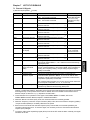
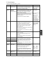
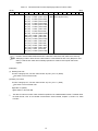
7.4 Command Codes and Response Codes
Table 7.2 lists the command codes available in remote registers RWw2, 10, 12, 14, 16, and 18. The response
codes (to be stored in RWr2, 10, 12, 14, 16, and 18) to those command codes are listed in Table 7.3.
The format of command codes in reading or writing from/to the inverter's function codes is shown in Table 7.4.
Table 7.2 Command Codes
Item
Code number
Read from function
code
Write to function
code
Description
0000H to 1163H Reads or writes data from/to
inverter's function codes.
0080H to 11E3H
Read from operation
method (run
command source)
007BH
Write to operation
method (run
command source)
00FBH
Read from the latest
and last alarm codes
0074H
Reads the content of the latest
and last alarm codes.
Read from the 2nd
and 3rd last alarm
codes
0075H
Reads the content of the 2nd
and 3rd last alarm codes.
Read reference
frequency
Write reference
frequency
006DH
Reads out the reference
frequency via CC-Link.
Writes the reference frequency.
(This frequency is effective only
when the frequency command
source is CC-Link.)
9696H: Clears alarm history.
9696H: Resets tripped state.
00EDH
Clear alarm history
Reset alarm
00F4H
00FDH
0000H: Link operation (CC-Link)
0001H: Terminal command for
external drive
0002H: Keypad operation
0003H: Others
0000H: Link operation (CC-Link)
0001H: Terminal command for
external drive
0002H: Keypad operation
Table 7.3
Code number
Normal (No error)
Not allowed to write
0002H
0003H
Invalid command code
Out of setting range
Change to y98=3
Change to y98=0 and F02=1
Change to y98=0, F02=0, and
F01=0
Lower byte: Latest alarm code
Higher byte: Last alarm code
(The contents of alarm codes are
detailed in Chapter 9.)
Lower byte: 2nd last alarm code
Higher byte: 3rd last alarm code
(The contents of alarm codes are
detailed in Chapter 9.)
The allowable setting range is from 0
to +/-20000. Specify the ratio of the
frequency relative to the maximum
frequency (defined by F03 in Hz)
being assumed as 20000.
Response Codes
Item
0000H
0001H
Remarks
Inverter's function codes should be
specified in the format shown in
Table 7.4.
Description
Execution of command code has been normally completed.
- Attempted to write to function code whose data cannot be
changed while the inverter is running.
- Attempted to write to function code whose data is being
edited from the keypad.
An invalid command code has been specified.
Write data is out of the allowable setting range.
23
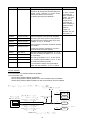
Table 7.4
Command Code Format for Specifying Inverter's Function Codes
(bit 15)
(bit 0)
15
14
13
Empty (Fixed to 0)
12
11
10
Function code group
00H (=0): F codes
01H (=1): E codes
02H (=2): C codes
03H (=3): P codes
04H (=4): H codes
05H (=5): A codes
06H (=6): o codes
07H (=7): S codes
08H (=8): M codes
0DH (=13): J codes
0EH (=14): y codes
0FH (=15): w codes
10H (=16): x codes
11H (=17): z codes
12H (=18): d codes
13H (=19): b codes
14H (=20): r codes
15H (=21): U codes
9
8
7
6
5
4
3
0: Read Function code number
(F00 to F99) 1: Write 00 to 99 (00H to 63H)
(E00 to E99)
(C00 to C99)
(P00 to P99)
(H00 to H99)
(A00 to A99)
(o00 to o99)
S00 to S99)
(M00 to M99)
(J00 to J99)
(y00 to y99)
(w00 to w99)
(x00 to x99)
(z00 to z99)
(d00 to d99)
(b00 to b99)
(r00 to r99)
(U00 to U99)
2
1
0
Inverter's communication dedicated function codes S01 to S03, S05, S06, and S19 are read-only.
Attempting to write to those function codes results in a "Not allowed to write" error (Response code:
0001H). These function codes are functionally equivalent to certain remote outputs and remote
registers.
(Examples)
(1) Reading from H95
Function code group: 04H, Function code number: 95 (=5FH), bit 7 = 0 (Read)
Set "045FH" to the command code
(2) Writing "10" to E20
Function code group: 01H, Function code number: 20 (=14H), bit 7 = 1 (Write)
Set "0194H" to the command code
Write data: 10 (000AH)
Set "000AH" to the write data
The data of inverter's function codes should be specified in the individual data formats. For details about
the data formats, refer to the RS-485 Communication User's Manual, Chapter 5, Section 5.2, "Data
Formats."
24
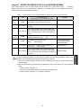
Chapter 8
ERROR PROCESSING FOR CC-Link NETWORK BREAKS
If the inverter detects a CC-Link network break such as broken wires, it trips with an alarm
by factory
default. The inverter's error processing after detection of a network break can be changed with inverter's
function codes o27 and o28 as listed in Table 8.1.
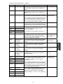
Table 8.1 Error Processing for CC-Link Network Breaks, Defined by Function Codes o27 and o28
o27
o28
0,
4 to 9
Invalid
1
2
Error Processing
after Detection of CC-Link Network Break
Immediately coast to a stop and trip with
Remarks
.
0.0 to 60.0 s
After the time specified by o28, coast to a stop and
trip with
.
0.0 to 60.0 s
If the communications link is restored within the
time specified by o28, ignore the communications
error. If a timeout occurs, coast to a stop and trip
with
.
3,
13 to 15
Invalid
Keep the current operation, ignoring the
communications error. (No
trip)
10
Invalid
Immediately decelerate to a stop.
Issue
after stopping.
The inverter's function
code F08 specifies the
deceleration time.
11
0.0 to 60.0 s
After the time specified by o28, decelerate to a
stop. Issue
after stopping.
Same as above.
0.0 to 60.0 s
If the communications link is restored within the
time specified by o28, ignore the communications
error. If a timeout occurs, decelerate to a stop and
trip with
.
Same as above.
12
In any of the following cases, the inverter does not perform error processing defined in Table 8.1 if it
detects a CC-Link network break, ignoring the occurrence of the error.
1) The CC-Link communications link has not been established once after the communications card
was turned ON.
2) Both run and frequency command sources specified are not CC-Link (that is, any of the following
three).
- Inverter's function code y98 = 0
- Terminal command LE is assigned to a terminal X and the LE is OFF.
- Inverter's function code y99 = 3, or y99 data = y98 data.
25
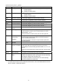
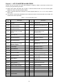
Chapter 9
LIST OF INVERTER ALARM CODES
Through CC-Link, the master can monitor the information on alarms (in Table 9.1) that have occurred in the
inverter, by using the following procedure.
(1) Specify which alarm code--latest, last, 2nd last, or 3rd last--should be read out, into the remote register
RWw8. (The alarm code will be stored in RWr8.)
(2) Specify command codes 0074H and 0075H (in remote registers RWw2, 10, 12, 14, 16, or 18) to read out
alarm codes.
(3) Use inverter's communication dedicated function codes M16 to M19 to read out the latest, last, 2nd last, and
3rd last alarm codes, respectively.
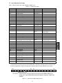
Table 9.1 List of Inverter Alarm Codes
Alarm
code
Alarm
code
Description
0 (00H)
No alarm
1 (01H)
---
Description
31 (1FH)
Memory error
Overcurrent
(during acceleration)
32 (20H)
Keypad communications error
2 (02H)
Overcurrent
(during deceleration)
33 (21H)
CPU error
3 (03H)
Overcurrent
(During running at constant
speed)
34 (22H)
Option communications error
(Communications card
hardware error)
5 (05H)
Grounding fault
35 (23H)
Option error
(CC-Link communications error)
6 (06H)
Overvoltage
(during acceleration)
36 (24H)
Operation protection
7 (07H)
Overvoltage
(during deceleration)
37 (25H)
Tuning error
8 (08H)
Overvoltage
(during running at constant
speed or stopped)
38 (26H)
RS-485 communications error
(COM port 1)
10 (0AH)
Undervoltage
44 (2CH)
Overload of motor 3
11 (0BH)
Input phase loss
45 (2DH)
Overload of motor 4
14 (0EH)
Fuse blown
46 (2EH)
Output phase loss
16 (10H)
Charger circuit fault
47 (2FH)
Speed mismatch
(Excessive speed deviation)
17 (11H)
Heat sink overheat
51 (33H)
Data saving error during
undervoltage
18 (12H)
External alarm
53 (35H)
RS-485 communications error
(COM port 2)
19 (13H)
Inverter internal overheat
54 (36H)
Hardware error
20 (14H)
Motor protection
(PTC/NTC thermistor)
56 (38H)
22 (16H)
Braking resistor overheat
57 (39H)
EN circuit failure
23 (17H)
Overload of motor 1
58 (3AH)
PID feedback wire break
24 (18H)
Overload of motor 2
59 (3BH)
Braking transistor broken
25 (19H)
Inverter overload
254 (FEH) Mock alarm
27 (1BH)
Overspeed
28 (1CH)
PG wire break
29 (1DH)
NTC thermistor wire break
26
Positioning control error
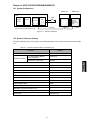
Chapter 10 APPLICATION PROGRAM EXAMPLES
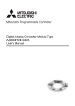
10.1 System Configuration
PLC
Power
supply
CPU
Q02CPU
Q61P A
-1
CC-Link
master unit
Station #1
Station #2
FRENIC -MEGA
FRENIC -MEGA
OPC -G1-CCL
OPC -G1-CCL
X20
Input
unit
( Set the
terminating
resistor switch
to ON)
QJ61BT11N
Insert the terminating resistor that comes
with the master unit between DA and DB.
CC-Link
o31=1
o31=2
Figure 10.1 System Configuration
10.2 Network Parameter Settings
In program examples given in this chapter, the network parameters of the master unit are set as listed in Table
10.1.
Table 10.1 Network Parameter Settings of the Master Unit
Parameter
Settings
Start I/O No.
Operation settings
0000
For units where a data link
error is detected
Clear input
At the time of CPU stop
Refresh
Type
Master unit
Mode
Remote Net Ver. 1 mode
Total number of slaves connected
2
Remote input (RX)
X1000
Remote output (RY)
Y1000
Remote register (RWr)
W0
Remote register (RWw)
W100
Special relay (SB)
SB0
Special register (SW)
SW0
Retry count
3
Automatic reconnection station count
1
For CPU down
Stop
Scan mode
Asynchronous
27
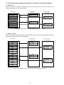
10.3 Relationship between Master Station Device and Remote I/O and Remote Register
(1) Remote I/Os
Figure 10.2 shows the relationship between the master station devices and remote I/Os (RX and RY) in the
program examples given on the following pages.
M a ste r sta tio n
R em ote sta tion
(Station #1 )
X100F
X101F
X102F
X103F
X104F
X105F
to
to
to
to
to
to
X1000
X1010
X1020
X1030
X1040
X1050
R X F to R X 0
R X 1F to R X 10
Y100F
Y101F
Y102F
Y103F
Y104F
Y105F
to
to
to
to
to
to
Y1 0 00
Y1 0 10
Y1 0 20
Y1 0 30
Y1 0 40
Y1 0 50
R Y F to R Y 0
R Y 1F to R Y 10
R em ote station
(Station #2 )
R X F to R X 0
R X 1F to R X 10
RY F to R Y 0
RY 1F to R Y 10
Figure 10.2 Relationship between Master Station Devices and Remote I/Os
(2) Remote registers
Figure 10.3 shows the relationship between the master station devices and remote registers (RWw and RWr) in
the program examples given on the following pages.
M a ste r sta tio n
R em ote sta tion
(Station # 1)
W 1 00
W 1 01
W 1 02
W 1 03
W 1 04
W 1 05
W 1 06
W 1 07
W 1 08
W 1 09
W 1 0A
W 1 0B
RW w0
RW w1
RW w2
RW w3
W 0 00
W 0 01
W 0 02
W 0 03
W 0 04
W 0 05
W 0 06
W 0 07
W 0 08
W 0 09
W 0 0A
W 0 0B
RW r0
RW r1
RW r2
RW r3
R em ote station
(Station #2 )
RW w0
RW w1
RW w2
RW w3
RW r0
RW r1
RW r2
RW r3
Figure 10.3 Relationship between Master Station Devices and Remote Registers
28
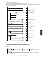
10.4 CC-Link Startup Program
Shown below is a CC-Link startup program example to run for ACPU.
No startup program is required for QCPU which starts up CC-Link communication with the network parameter
settings made in the master unit.
X00
X0F
PLS
M300
Permission to write settings
SET
M301
Request to write settings
Unit failure Unit ready
M300
M301
TO
H0
H1
K2
K1
Number of units connected = 2
TO
H0
H20
H1101
K1
Station info on inverter (Station #1)
TO
H0
H21
H1102
K1
Station info on inverter (Station #2)
RST
M301
Writing of settings completed
SET
Y00
Permission to bit output (If OFF, no RY
output yet.)
PLS
M302
Permission to write settings
SET
M303
Request to write settings
SET
Y06
Link start request
RST
Y06
Cancel of link start request
M9038
One scan ON
after RUN
X00
X0F
Unit failure Unit ready
M302
M303
X06
Link startup
normally
completed
RST
M303
Link startup completed
X07
FROM
Link startup
abnormally
terminated
H0
H668
D315
K1
Read link special device
RST
Y06
Cancel of link start request
RST
M303
Link startup completed
Figure 10.4 CC-Link Startup Program Example (for ACPU only)
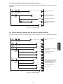
10.5 Program Example Using the Inverter Running Status Read
The program example shown below turns ON the auxiliary relay M100 when FRENIC-MEGA station #1 starts
running.
X0
X0F
X1
BMOV
Unit
failure
M0
SW80
K4MO
K4
Read out data link status of slave
stations
M100
Turn ON the auxiliary relay M100
Unit Host station
ready being linked
X1002
Inverter running (RX02)
Figure 10.5 Program Example
29
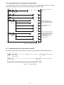
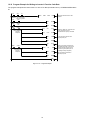
10.6 Program Example for Changing the Operation Mode
The program example shown below switches the operation mode of FRENIC-MEGA station #1 to network
operation (specifying CC-Link as both run command and frequency command sources).
X0
X0F
X1
BMOV
Unit failure
M0
M300
SW80
K4
Read out data link status of slave
stations
Unit Host station
ready being linked
X20
PLS
M300
SET
M301
MOV
H0FB
W102
MOV
H0
W103
SET
Y100F
RST
M301
SET
M302
Writing
ON
Command code
execution
completed
M302
K4M0
X100F
MOV
Command code
execution
completed
W2
D2
RST
Y100F
RST
M302
Write the “Operation mode”
command code (HFB) into RWw2,
and object data (H0000) into RWw3
Turn command code execution
request (RYF) ON
When the command code execution
completed signal (RXF) is turned ON,
the response code (RWr2) is read
out into D2. (0: Reading out has
normally finished.)
Turn command code execution
request (RYF) OFF
END
Figure 10.6 Program Example
10.7 Program Example for Specifying Run Command
The program example shown below writes the run forward command (FWD) into FRENIC-MEGA station #1
X0
X0F
X01
BMOV
Unit failure
SW80
K4M0
K4
Unit Host station
ready being linked
Read out data link status of slave
stations
M0
Y1000
Run ON
END
Figure 10.7 Program Example
30
Run forward command (RY0)
10.8 Program Example for Monitoring the Output Frequency
The program example shown below reads out the output frequency from FRENIC-MEGA station #1 into data
register D1.
X00
X0F
X01
BMOV
Unit
failure
M0
SW80
K4M0
K4
Read out data link status of slave
stations
Unit Host station
ready being linked
X20
MOV
H1
W100
Write the monitor item code (H01) of
output frequency into RWw0
Writing
ON
Y100C
Turn monitor command (RYC) ON
X100C
MOV
W0
D1
Monitoring
Turning RYC ON reads out the output
frequency from the remote register
(RWw0) into D1.
END
Figure 10.8 Program Example
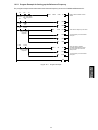
10.9 Program Example for Reading from the Inverter's Function Code Data
The program example shown below reads out the F07 data (Acceleration time 1) from FRENIC-MEGA station
#1
X0
X0F
X1
BMOV
Unit failure
M0
M300
M301
SW80
K4
Read out data link status of slave
stations
Unit Host station
ready being linked
X20
Writing
ON
PLS
M300
SET
M301
H7
W102
SET
Y100F
RST
M301
SET
M302
X100F
MOV
Command code
execution
completed
M302
K4M0
Write the “Read F07” command code
(H07) into RWw2
Turn command code execution
request (RYF) ON
X100F
Command code
execution
completed
MOV
W3
D1
MOV
W2
D2
RST
Y100F
RST
M302
END
Figure 10.9 Program Example
31
When the command code execution
completed signal (RXF) is turned ON,
the acceleration time 1 (RWr3) and
response code (RWr2) are read out
into D1 and D2, respectively
Turn command code execution
request (RYF) OFF
10.10 Program Example for Writing to Inverter's Function Code Data
The program example shown below writes 3.0 s to the F07 data (Acceleration time 1) of FRENIC-MEGA station
#1.
X0
X0F
X1
BMOV
Unit failure
M0
M300
M301
K4M0
K4
PLS
M300
SET
M301
MOV
H87
W102
MOV
H12C
W103
SET
Y100F
RST
M301
SET
M302
Writing
ON
Read out data link status of slave
stations
X100F
Command code
execution
completed
M302
SW80
Unit Host station
ready being linked
X20
X100F
MOV
Command code
execution
completed
W2
RST
D2
Write the “Write F07” command code
(H87) into RWw2, and the
acceleration time (H12C) into RWw3
Turn command code execution
request (RYF) ON
When the command code execution
completed signal (RXF) is turned ON,
the response code is read out from
the remote register (RWr2) into D2.
(0: Writing normally completed.)
Y100F
Turn command code execution
request (RYF) OFF
RST
M302
END
Figure 10.10 Program Example
32
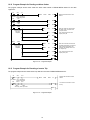
10.11 Program Example for Setting up the Reference Frequency
The program example shown below writes the reference frequency 50.00 Hz to FRENIC-MEGA station #1.
X0
X0F
X1
BMOV
Unit failure
M0
SW80
M300
Writing
ON
M301
X100D
MOV
Frequency setting
completed
M302
K4M0
K4
Unit Host station
ready being linked
X20
PLS
M300
SET
M301
K5000
W101
Write reference frequency into RWw1
SET
Y100D
Turn the frequency command RAM
(RYD) ON
RST
M301
SET
M302
W2
D2
X100D
MOV
Frequency setting
completed
RST
Y100D
RST
M302
END
Figure 10.11 Program Example
33
Read out data link status of slave
stations
When the frequency setting
completed signal (RXD) is turned
ON, read out the response code
(RWr2) into D2
Turn the frequency command RAM
(RYD) OFF
10.12 Program Example for Reading out Alarm Codes
The program example shown below reads out alarm codes stored in FRENIC-MEGA station #1 into data
register D1.
X0
X0F
X1
BMOV
Unit failure
SW80
K4
Read out data link status of slave
stations
Unit Host station
ready being linked
M0
X20
M300
Writing
ON
M301
X100F
PLS
M300
SET
M301
H74
W102
SET
Y100F
RST
M301
SET
M302
MOV
W3
D1
MOV
W2
D2
MOV
Command code
execution
completed
M302
K4M0
Write the “Read from the latest and
last alarm codes” command code
(H74) into RWw2
Turn command code execution
request (RYF) ON
X100F
Command code
execution
completed
RST
Y100F
RST
M302
When the command code execution
completed signal (RXF) is turned ON,
read out alarm code (RWr3) and
response code (RWr2) into D1 and
D2, respectively
Turn command code execution
request (RYF) OFF
END
Figure 10.12 Program Example
10.13 Program Example for Resetting a Inverter Trip
The program example shown below resets a trip that has occurred in FRENIC-MEGA station #1.
X0
X0F
X01
BMOV
Unit failure
M0
SW80
K4M0
K4
Read out data link status of slave
stations
Unit Host station
ready being linked
X101A
X20
Y101A
Alarm
Alarm
status flag reset request ON
END
Figure 10.13 Program Example
34
Turn X20 from ON to OFF to reset
the trip
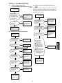
Chapter 11 TROUBLESHOOTING
(1)
Option communications error
(Communications card hardware error) (
)
If this error occurs, analyze the cause of the error
referring to the RAS information in the master CPU. For
the access to the RAS information and its contents, see
the master user’s manual.
has occurred.
Do the CC-Link
versions of the slave
and master stations
match with each other?
(master station version
1.xx, slave station
version 2.xx)
NO
Match the versions of
the master station and
the slave station with
each other.
has occurred.
Is the power to the
master shut down? Or
is the master unit
detached?
YES
Is the option mounted
on the inverter
correctly?
(2) Option error (CC-Link communications error)
(
)
YES
The option or inverter
unit may be defective.
Contact Fuji Electric.
YES Turn ON the power to
the master, reset the
CPU, and reset the
inverter. Operation
can be resumed.
NO
NO
Does the detailed RAS
information in the CPU
module indicate that
an error has occurred?
Mount the option into
place referring to this
manual.
YES Remove the error
factor from the station
concerned and reset
the inverter.
NO
(3) Commands via CC-Link not reflected
NO
Is the station address
setting (o31) correct?
Commands received
via CC-Link are not
reflected.
Make the station
address of o31 match
that in the system
configuration
definition.
YES
Is the data of function
code y98 set to any
value other than “0” ?
NO
Correct y98 data.
Any of the following
wiring problems?
Wire(s) broken
Wrong connection
to the terminal block
Signal lines wired in
parallel with power line
Terminating resistor
setting
CC-Link cable not used
Maximum cable length,
inter-station cable
length, and the number
of units connected, out
of specifications
YES
Is [LE] assigned to X
function?
YES Turn ON the
appropriate contact.
NO
Is the L. ERR LED on
the option lit or
blinking?
YES
Check the CC-Link
wiring and the
sequencer CPU
settings.
NO
Match the setting of
o30 with that of the
master.
NO
Is the setting of the
function code o30
"CC-Link extension"
correct?
NO
YES
Is the command code
format for specifying
function code(s)
correct?
NO
The option or inverter
unit may be defective.
Contact Fuji Electric.
Correct the format,
referring to the RS-485
Communication User’s
Manual, Chapter 5.
YES
Is data written into the
buffer memory areas
(RX, RY, RWw, RWr)
as assigned to
addresses?
NO
Check writing to the
I/O memory areas.
YES
The option or inverter
unit may be defective.
Contact Fuji Electric.
35
YES
Correct the wiring.
Chapter 12 SPECIFICATIONS
12.1 General Specifications
Table 12.1 lists the environmental requirements for the inverter equipped with the communications card. For the
items not covered in this section, the specifications of the inverter itself apply.
Table 12.1 Environmental Requirements
Item
Specifications
Site location
Indoors
Surrounding temperature
Refer to the FRENIC-MEGA Instruction Manual, Chapter 2.
Relative humidity
5 to 95% (No condensation)
Atmosphere
The inverter must not be exposed to dust, direct sunlight, corrosive gases,
flammable gases, oil mist, vapor or water drops.
Pollution degree 2 (IEC60664-1) (Note)
The atmosphere can contain a small amount of salt.
(0.01 mg/cm2 or less per year)
The inverter must not be subjected to sudden changes in temperature that will
cause condensation to form.
Altitude
1,000 m max.
Atmospheric pressure
86 to 106 kPa
Vibration
Refer to the FRENIC-MEGA Instruction Manual, Chapter 2.
Applicable inverters
FRENIC-MEGA series of inverters, ROM Ver. 0500 or later
(Note) Do not install the inverter in an environment where it may be exposed to lint, cotton waste or moist dust or dirt
which will clog the heat sink of the inverter. If the inverter is to be used in such an environment, install it in a
dustproof panel of your system.
12.2 CC-Link Specifications
Table 12.2 lists the CC-Link specifications for this communications card. For the items not covered in this
section, the specifications of the CC-Link apply.
Table 12.2 CC-Link Specifications
Item
Name
Station type
Number of units
connectable
Number of stations
occupied
Specifications
CC-Link communications card
Remote device station
Max. 42 units (one station occupied per unit)
1
CC-Link version
The communications card complies with CC-Link versions 1.10 and 2.00. It can
be configured with the function code o30 as follows:
1 station occupied (CC-Link version 1.10): o30 = 0 or 1
1 station occupied with 2X setting (CC-Link version 2.00): o30 = 2
1 station occupied with 4X setting (CC-Link version 2.00): o30 = 3
1 station occupied with 8X setting (CC-Link version 2.00): o30 = 4
Setting invalid: o30 = Other than the above data
Terminal block for
connection
5-pin terminal block (M3×5 screws)
Communications cable
CC-Link dedicated cable
- Use the CC-Link dedicated cable in CC-Link system.
- Using a cable other than a CC-Link dedicated cable does not assure the
CC-Link system performance.
- For further information about the CC-Link dedicated cable specifications and
inquiries, visit the CC-Link Partner Association's website at:
http://www.cc-link.org/eng/t_html/top.html
36
Table 12.2 CC-Link Specifications (Continued)
Item
Specifications
Station address
1 to 64. The station address can be specified with the inverter's function code o31.
Transmission speed
(Baud rate)
10 Mbps (o32 = 4), 5 Mbps (o32 = 3), 2.5 Mbps (o32 = 2), 625 kbps (o32 = 1),
156 kbps (o32 = 0)
The transmission speed can be specified with the inverter's function code o32.
LED status indicators
L.RUN: Lights when the communications card is normally receiving refresh data.
It goes off if data transmission is interrupted for a certain period of time.
L.ERR: Lights when a communications error has occurred. It blinks if the station
address (o31) or the transmission speed (o32) is changed when the
power is on.
RUN:
Lights during normal communication. It blinks when mismatch in CC-Link
version settings is found or the connection between the inverter and the
communications card is cut.
SD:
Lights during data transmission.
RD:
Lights during data reception.
37
38
CC-Link Communications Card
"OPC-G1-CCL"
Instruction Manual
First Edition, June 2008
Fifth Edition, April 2011
Fuji Electric Co., Ltd.
The purpose of this manual is to provide accurate information in the handling, setting up and operating of the
CC-Link Communications Card for the FRENIC-MEGA series of inverters. Please feel free to send your
comments regarding any errors or omissions you may have found, or any suggestions you may have for
generally improving the manual.
In no event will Fuji Electric Co., Ltd. be liable for any direct or indirect damages resulting from the application of
the information in this manual.
Fuji Electric Co., Ltd.
Gate City Ohsaki, East Tower, 11-2, Osaki 1-chome,
Shinagawa-ku, Tokyo, 141-0032, Japan
URL http://www.fujielectric.co.jp/
Phone: +81 3 5435 7283 Fax: +81 3 5435 7425
URL http://www.fujielectric.com/
2011-04 (D11d/F08) 1CM