1
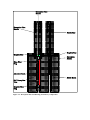
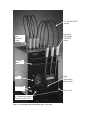
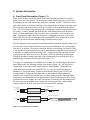
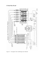
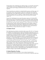
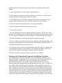
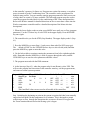
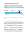
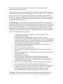
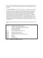
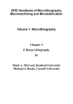
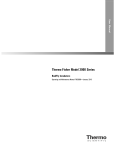
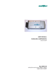
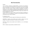
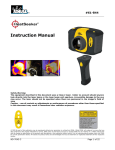
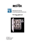
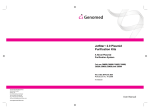
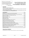
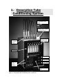
1. Desorption Tube Conditioning System 1/8” Flexible PTFE Tubing Stainless Steel Handle with PTFE Sleeve Quick Disconnect Fittings High-Precision Metering Valve Rotameters Gas Switch Heater Switch L.E.D. Digital Readouts Power Switch Heater Demand Light Figure 1-1 – Desorption Tube Conditioning Oven – Front View I. Introduction A. Theory of Operation The Desorption Tube Conditioning Oven is recommended for the flow conditioning of packed glass-lined stainless steel (GLT) or silco-coated desorption tubes as well as for the flow conditioning of desorption tube needles (Figure 1-2). A high purity gas such as helium or nitrogen is recommended for use in this system to purge the packed desorption tubes while baking out at elevated temperatures. By proper conditioning of the desorption tubes and adsorbents, one can be assured that no foreign contaminants will interfere with or contribute to the composition of the samples being analyzed. The system consists of six flow adjustable rotameters and a heater block with six ports (0.40" I.D. x 4.0" deep) for the cleaning of six desorption tubes or needle caps simultaneously at temperatures up to 350°C. A Watlow precision programmable temperature controller provides the heater circuit to heat the blocks and permits the programming of the temperature at which the tubes are to be conditioned. Temperature programs of up to six steps with various ramp cycles and hold times can be programmed into the controller for the unattended conditioning of the desorption tubes. Programs are stored in the system's memory. Accuracy of the programming temperatures is +/-.1% of the full scale reading. An L.E.D. digital readout displays the set temperature and the actual temperature of the system, and the bubble meters indicate the flow through each desorption tube or needle. B. Safety - Warning Messages WARNING Do not condition tubes or needles above 350 °C otherwise damage may occur to heater blocks or internal circuitry. WARNING Maximum gas pressure is 60 P.S.I. WARNING or Nitrogen. Do NOT use Hydrogen Gas in the Conditioning Oven. Use only Helium WARNING Make sure that only fuses with the required current rating and of the specified type are used for replacement. The use of incorrect or makeshift fuses or the short-circuiting of fuse holders creates a shock hazard for the operator and can damage the instrument. WARNING Do NOT increase temperature range of heat overload current. WARNING If the System overheats, return to manufacturer for all service. Any adjustments, maintenance or repair of the opened instrument while it is connected to a power source must be avoided. WARNING Do NOT leave Conditioning Oven heaters in the heated ON position unattended overnight. The Conditioning Oven heaters rapidly heat and cool to their final operating temperatures and therefore, in order to prolong their life and avoid premature failure of the system they should be turned off when not actively being utilized to condition tubes or needles. WARNING Use grounded outlet only. Connecting the Conditioning Oven to a power source which is not equipped with a protective earth ground contact creates a shock hazard for the operator and can damage the instrument. WARNING Hot surface exposed. Do NOT TOUCH Desorption Tubes or needles when removed from heater block. Use PTFE Handles to remove tubes & needles from block. Allow to cool before touching. WARNING Do Not condition needles on the desorption tubes. Condition desorption tubes and needles separately using appropriate handles. B. Specifications 1. Electrical Specification Power Requirements Voltage - 110 VAC Current - 10 amps maximum Electrical Cord - 110 v/grounded outlet Temperature Controller Heater Circuit - Accuracy - +/-.1% of full scale - Range - up to 350°C Heater output - 115 volt, 600 watt Sensor Input - Platinum Resistance Thermometer Heater Cartridges - 4 each - 115 v, 150 watts Digital Readout for set & actual temperatures 3 or 4 digit Temperature Range - Room Temperature to 350°C Programmable – autocalibration temperature controller 2. Gas / Pressure Specification Type - Nitrogen or Helium (high purity) Maximum pressure - 60 P.S.I. Flow - Maximum 50 ml / min per tube - Maximum total 300 ml / min Quick disconnects - automatically turn off gas 3. Weight and Dimensions Weight - 12 pounds Size - 9" wide x 9" deep x 13" high C. Warranty & Service Warranty -The Desorption Tube Conditioning System is warranted against defects in material or workmanship for a period of 90 days commencing from the date of shipment from the warehouse of Scientific Instrument Services in Ringoes, NJ, hereafter referred to as the company. The company's liability on the Desorption Tube Conditioning System and accessories is limited to the cost of correcting the defect in the product. In no case shall the company be liable for consequential or special damages. The system should not be run unattended overnight. The company will not correct defects caused by buyers negligence. The company does not guarantee or warrantee the product for any particular purpose. The companies warranty shall end 90 days after shipment. Extended Warranty - An extended one year warranty for parts and labor is available if purchased within 30 days of shipment of the unit. The one year extended warranty will cover parts and labor to repair the Desorption Tube Conditioning System within the facilities of Scientific Instrument Services. Service on customers’ facilities is not available. Service and Repair - The Condition System should be serviced only by qualified SIS staff. Any equipment to be serviced under warranty or otherwise should be sent to the repair facilities of Scientific Instrument Services in Ringoes, NJ. No on- site service is available. A Return Authorization Number (RA#) must be obtained from the offices of Scientific Instrument Services before any equipment is returned. Scientific Instrument Services, Inc. 1027 Old York Road Ringoes, NJ 08551 Attn: Repair Department RA#________________ Phone: (908) 788-5550 Figure 1-2 – Desorption Tube Conditioning Oven Theory of Operation. 1/8” Flexible PTFE Tubing Quick Disconnect Fitting Desorption Tube handle with PTFE Sleeve Cooling Rack Fan High Temperature Reset Switch Fuse Holders Power Cord 1/8” Swagelok Fitting for Carrier Gas (N2 or He) Figure 1-3 – Desorption Tube Conditioning Oven – Rear View II. System Description A. Front Panel Description (Figure 1-1) Three on/off switches are present on the front panel including a main power switch, a heater switch and a gas switch. The main power switch controls the power to the entire Conditioning Oven, to the temperature controller, and other switches. The heater switch turns on the power to the heater cartridges in the heater block and begins its heating cycle. The carrier gas switch turns on the carrier gas to permit its flow through the desorption tube. An L.E.D. digital readout displays the set temperature and the actual temperature of the system. A heater demand light indicates the actual heating demand of the heater blocks. If the demand light is bright red the heater is on; heater is off when there is no light. If the demand light is dim red, the heater is unplugged or an open circuit exists. Each of the flow rates for the desorption tubes and needles can be monitored by the six rotameters and flows adjusted with the high precision metering valves. The self contained system includes six adjustable bubble rotameters with flow ranges of 0 to 50 ml/min, one for each of the tubes or needles to be conditioned. The recommended flow rate is 20 ml/min. Flow meter calibration data for air and helium are listed in Table I. Each of the flows through the tubes can be independently controlled or flow turned off to that port via a high precision metering valve. A single electrically operated solenoid valve turns the gas flow off or on to all the ports via the Gas Switch on the front panel. The quick disconnect fittings on the top of the Conditioning Oven turn the flow off to individual gas flow lines when disconnected (Figure 1-5). Two types of Conditioning Oven Handles are available, one for attaching the desorption tubes and the other for attaching stainless steel needles (Figure 1-4). All systems are shipped with six desorption tube handles and two needle handles. The handles are constructed from stainless steel with PTFE sleeves. The gas connection fitting is a standard 1/8" Swagelok fitting. Graphite seals with metal inserts (part #781015) are recommended for sealing the desorption tubes to the handles during conditioning. Graphite seals are physically soft but have excellent sealing properties and temperature limits and are recommended for most applications with the Conditioning system. When soft materials such as graphite are used, a metal tube is inserted inside the center hole in the seal to prevent the graphite from closing and restricting gas flow. Other sealing washers could also be used if preferred for lower temperature cleaning. External Thread for Needle Cap 1/8" Swagelok Fitting Gas Flow Desorption Needle S.S. Desorption Needle Handle for Cleaning Needles Part #781014 Internal Thread for Desorption Tube Gas Flow GLT Desorption Tube S.S. Desorption Tube Handle for Conditioning Tubes Part #781013 Figure 1-4 – Conditioning Oven Handles B. Rear Panel Description (Figure 1-3) Electrical power is provided from a standard 110 volt, 10 amp grounded outlet. A single 1/8" Swagelok fitting on the back of the Conditioning System provides for the attachment of the carrier gas from its source. An external high temperature reset switch is located in the rear of the oven so that if temperatures exceed 350°C on the heater block, the external reset will open and heat to the block will stop. This switch can be reset by simply pushing this red button once the block has cooled. Two Slo Blo fuses are mounted in the rear of the Conditioning System to handle the initial surges of the Main Power and Heater switches when they are turned on. In addition, a three inch fan enclosed on the back side of the Conditioning System provides a steady flow of air through the system to maintain the temperature of the temperature controller, rotameters, and other components inside the system at an acceptable level and to provide for cooling of the heater block once the heater circuitry is turned off. After conditioning the desorption tubes and needles are removed and placed in a cooling rack attached to the back of the Conditioning System and cooled under constant flow. As soon as the tubes are touchable (5-10 min), they are immediately capped on both ends with stainless steel caps with PTFE seals that have also been conditioned. III. Gas Flow Circuit Figure 1-5 – Desorption Tube Conditioning Oven Schematic The Desorption Tube Conditioning Oven schematic (Figure 1-5) pictorially represents the overall operation of the system including the gas flow and heater circuits. A 110 volt outlet is required, and 10 amps provides the total electric power required for system operation. The self contained system includes six adjustable bubble rotameters with flow ranges of 0 to 50 ml/min, one for each of the tubes or needle to be conditioned. Each of the flows through the tubes can be independently controlled via a microneedle valve and the flow turned off to that port if no flow is required. A single electrically operated solenoid valve (v) turns the gas flow off or on to all the ports via the Gas Switch on the front panel (Figure 1-5). On top of the Conditioning Oven six quick disconnects connect to 1/8" flexible PTFE tubing to provide gas flow through the desorption tubes and needles during conditioning. When a quick disconnect is removed the gas flow is automatically closed to that port. By providing gas flow from a carrier gas such as high purity nitrogen or helium through the desorption tubes and needles while conditioning, it can be assured that no oxygen enters the desorption tubes which could destroy the adsorbent material. Impurities from the inside of the desorption tubes and needles are flushed from the interior surface of these parts. A single 1/8" fitting on the back of the Conditioning System is provided for the attachment of the carrier gas from the source (Figure 1-5 - (Gas in)). IV. Heater Circuit The Conditioning Oven includes a heater block with six ports (I.D. 0.40” x 4.0” deep) for the cleaning of six desorption tubes or needles simultaneously at temperatures up to 350° C. A Watlow precision programmable temperature controller permits the programming of the temperature at which the tubes are to be conditioned. The heater block contains a platinum resistance thermometer (PRT) for accurate (+/-.1%) temperature readout and provides the feedback to the temperature controller to maintain the heater block temperature. A J type thermocouple (TC) is also present in the heater block and serves as the temperature sensor for the high temperature limit control circuit. Four 3/8” diameter, 150 Watt heater cartridges heat the aluminum heater block. The heater cartridges are wired in parallel and are fused by their own 10 amp slow-blow fuse. A separate heater switch on the front panel permits the manual turning OFF and ON of the power to the heater cartridges. A 60° C heat overload sensor is attached to the inside of the Conditioning Oven case to protect against the excessive heating of the circuitry inside the Oven case. Two overheat protection circuits are built into the Conditioning Oven as described below. The heater indicator light (on the front panel) displays the power demand for the heater cartridges. When brightly lit, power is being supplied to the heater cartridges; when off, no power is supplied to the heaters. When dimly lit, the circuitry to the heater cartridges is open within the Conditioning Oven. A. Heater Protection Circuitry A heat overload thermostat (internal 60° C reset switch) is located inside the Conditioning Oven case to prevent the interior case and electrical components from being subjected to excessive heat. If the oven case should exceed 60° C due to a circuit failure (such as failure of the cooling fan to operate), this overload sensor will open the circuit that provides power to the heater cartridges. This overheat sensor can only be reset by allowing the system to cool, opening the Conditioning Oven case, and manually resetting the internal overload reset switch. If the heat overload thermostat should open when operating the system, the entire Condition Oven should be returned to the factory for service. Service should only be performed by qualified electrical technicians knowledgeable of the system electrical circuits. A high temperature limit control board with an external high temperature reset switch (Figure 1-3 and Figure 1-5 - Hi temp reset) prevents the heater block temperature from exceeding 350° C. If the block temperature exceeds 350° C, the external reset switch will automatically open the power circuitry to the heater cartridges. Power cannot be restored to the heater cartridges until the heater blocks are allowed to cool and the external reset switch is manually reset (Figure 1-5). Note: Do not exceed 350° C for the Conditioning Oven heater blocks. Higher temperatures will damage internal circuitry and create a potential meltdown and electrical hazard. B. Watlow Temperature Controller Figure 1-6 – Watlow temperature controller keypad/display The Watlow microprocessor based temperature controller (Figure 1-6) provides the heater output to the Conditioning Oven heater blocks. The system can either be run isothermally (Manual Operation) at a set and constant temperature or alternatively can be temperature programmed or temperature ramped (Automatic Operation) via a user selected temperature program. Procedures of up to six steps with various ramp cycles and hold times can be stored in the temperature controllers memory for the automatic ramping of temperatures as the desorption tubes are conditioned. Accuracy of the programming temperatures is +/- .1% of the full scale reading. Two 0.56" red LED’s display the set and actual temperatures for the heater block. Description of the Keys and Display 1.Upper Display (Actual heater block temperature) The red 0.56” (14 mm) high, seven segment, four digit LED display indicates the actual heater block temperature, in addition to parameter values, or an open sensor. When powering up, the displays will be blank for 8 seconds. 2. Lower Display (SET temperature) The red 0.56 (14 mm) high, seven segment, four digit LED display, indicates the temperature SET point for the system. This value can either be set manually via the up/down arrows or is defined and displayed in the automatic mode by the user selected temperature program. UP/DOWN keys - The UP/DOWN arrow keys are used to manually set the desired value for the SET temperature as displayed in the lower LED display. When pressed down simultaneously for 3 seconds, the SETUP Menu appears. 3. UP Key - Increases the value of the SET temperature LED display. A single light touch increases the value by one. Hold the key down to increase the value at a rapid rate. 4. DOWN Key - Decreases the value of the SET temperature LED display. A single light touch decreases the value by one. Hold the key down to decrease the value at a rapid rate. 5. HOLD/RUN Key - Used to run or hold a temperature program. Press once to load the temperature program. Press a second time to start the temperature program. Pressing a third time will stop the temperature program and restore the controller to the manual (isothermal mode of operation). 6. HOLD/RUN LED - Lit when the control in running. When blinking, press the HOLD/RUN key again to begin running the temperature program. 7. MODE Key - Steps through the various menus such as the temperature program menu. Also automatically enters data before proceeding to the next parameter. For additional features, control and system setup refer to the Watlow Controller Manual. Temperature Controller System SETUP The purpose of the SETUP menu is to define the various operating parameters and condition of the temperature controller. These user selectable parameters include the conditions of controller operation, the calibration parameters, rate of heating, sensor input type, temperature scale (°C or °F), display decimal point location, and temperature range. The Watlow temperature controller has already been preset to the correct operating parameters at the factory and the user should not normally have needed to alter these factory settings. The SETUP Menu is entered by pressing both the UP and DOWN arrow keys simultaneously for 3 seconds. The values presently in the controller on the Conditioning Oven have been factory selected for the correct operation of the Conditioning Oven. It is NOT recommended that they be changed. For a detailed description of these parameters and the selections available refer to the Watlow Users Manual. The factory preset values are listed below. Setup Menu LOC O In rtd C_F C rL 0 rH 400 Ot1 ht HYS1 2 rtd din PtYP rAte gSd 0 POUt Cont Operation Menu Prog no Pb1 6 rE1 0.36 rA1 0.27 Ct1 5 CAL 0 AUt 0 Isothermal or Manual Mode Operation of the Watlow Controller To operate the Watlow controller in the isothermal or manual mode of operation the following steps are used. 1. Turn on the Main Power Switch on the Conditioning Oven. 2. Turn on the Gas Switch. 3. Use the UP/DOWN arrow keys to select the desired temperature of the heater blocks (SET temperature is displayed on the lower LED display of the Watlow controller). 4. Turn on the heater switch. Within 5 minutes the heater blocks temperature (Upper display) should reach the same value as the SET temperature (Lower display). 5. Attach the desorption tubes and needles to the appropriate handles. 6. Insert the tubes and needles into the heater block ports. Programmed Temperature Ramp or Automatic Mode of Operation In order to operate the Watlow temperature controller in an automatic or preprogrammed temperature ramp the following steps should be followed. Before running the system with a temperature program, the user must have previously entered the ramp temperature program stored in the systems memory as described in a subsequent section of this manual. 1. Turn on the Main Power Switch on the Conditioning Oven. 2. If the temperature program has not been installed, refer to the next section on how to install the temperature ramp program before proceeding. 3. Turn on the heater switch. Within 5 minutes the heater blocks temperature (Upper display) should reach the same value as the SET temperature (Lower display). 4. Attach the desorption tubes and needles to the appropriate handles. 5. Insert the tubes and needles into the heater block ports. 6. Turn on the Gas Switch. 7. Press the HOLD/RUN switch to load the temperature program. The first step # of the program will be displayed. You can either begin the temperature program at this first step or you can use the UP/DOWN arrows to increment to a subsequent step in the program. 8. Press the HOLD/RUN switch again to begin the temperature program 9. The lower display will indicate the program set temperature and the upper display will indicate the actual temperature of the heater blocks. Both displays should be within 1° of each other during the temperature program cycle. 10. The system will reset itself when the temperature program is done. To manually stop or interrupt the temperature program during a run, push the HOLD/RUN switch. This will return the controller to the manual (isothermal) mode of operation. For further information refer to the Watlow Controller User’s Manual. Setting up the Temperature Program for the Watlow Controller It is often preferred to ramp the temperature of the Conditioning Oven heaters up to a predetermined rate of temperature rise to a set temperature, hold at that temperature for a predetermined time, and then allow the blocks to automatically cool down to a predetermined temperature. For example, desorption tubes packed with Tenax are routinely temperature programmed from ambient temperature up to 300° C at a rate of 4° C per minute while constantly purging with helium or other high purity carrier gas at flows not less than 20 ml per minute. The traps are held at the high temperature for four hours. After this time the power to the heater blocks are turned off, the desorption tubes are removed, allowed to cool, and are finally capped for storage. Traps prepared in this manner exhibit excellent adsorptive capacity and contain no organic background (bleed or artifact peaks) when analyzed by GC/MS. The temperature controller can be quickly and easily set up to conduct this automatic temperature ramp. Programs set up are stored in the controller’s memory for future use. Programs are retained in memory, even when power is turned off to the Conditioning Oven. The controller can be programmed for multiple ramp profiles. You can continue entering program parameters until you run out of steps, there are a total of 24 steps available. The following program steps are used to create the program described above for the conditioning of the Tenax desorption tubes. Refer to the Watlow manual for detailed directions on how to enter these values into the Watlow temperature controller and for a detailed description of the Menu selection descriptions. 1. When the lower display reads set point, press MODE once until you see Prog (program parameter). Use the UP arrow key to select YES in the upper display. Press the MODE key once again. 2. The controller asks you for the STEP (Step Number). The upper display reads 1 (Step #1). 3. Press the MODE key to enter Step # 1 and you are then asked for StYP (step type). The default is END. Use the UP/DOWN arrow keys to select SoAh (soak) and then press the MODE key again to enter this value. 4. Use the below table to continue entering the parameters from left to right through the table. Remember that the MODE key is used to progress through the menu, and the UP/DOWN keys are used to select parameters and their values. 5. The program must end with the END statement 6. At the last step (Step # 5), when the program asks for rtn (Return), select YES. This will save the program and corrections in the controller memory, exit the program menu, and return to normal system operation. Step 1 2 3 4 5 StYP SP HOUr Min Sec Ent1 Ent2 rATE Step TYpe Set Point * * SoAh 0 10 0 OFF OFF — — StPt 300 On OFF 4.0 — SoAh 4 0 0 On OFF — — StPt 20 On OFF 0.0 — END — OFF *Ent1 and Ent2 values are not used on all models of the controllers. End rtn nO nO nO nO YES Step 1 initializes the beginning set point to the current set point which has been manually entered and will hold it at this temperature for 10 minutes. This is designed to permit sufficient gas to flow through the desorption tube to remove all traces of oxygen from the Tenax contained therein before the heating cycle is begun. Step 2 sets a final temperature of 300° C which will be attained at a ramp rate of 4° per minute. Step 3 holds the heater blocks at the high temperature (300° C) for a total of 4 hours. Step 4 reinitializes the system to 20° C and begins the cooling cycle. Step 5 ends the program. Figure 1-7 – Funnel with Desorption Tube V. Standard Procedures for Preparing and Conditioning Desorption Tubes Upon installation, a carrier gas line from a high purity gas source such as nitrogen or helium is attached to a single 1/8" Swagelok fitting on the back of the Conditioning System. On top of the Conditioning System six quick disconnects are connected to 1/8" flexible PTFE lines to provide gas flow through the desorption tubes and needles during conditioning. The electrical connection is made with a 110 VAC plug which is grounded. Desorption tubes which have graphite seals and needles which have either graphite or graphitized Vespel seals screw into the Conditioning Oven handles. Desorption Tubes are prepared in the following manner for use in the TD-5. A. Washing - All desorption tubes should be thoroughly cleaned by a detergent and water rinsing followed by an acetone rinse in an ultrasonic bath and air dried. Appropriate ventilation, safety glasses and gloves should be used. Tubes are baked out in an oven at 100°C. Cleaning by additional solvents such as methanol may be required depending on the applications of the user. It is important to remove all solvent residues by thoroughly baking out the tubes. B. Silylating - Silylation with a suitable silylation reagent such as Dimethyldichlorosilane (DMDCS) under the trademark Silon™ T (Pierce Co.) is recommended depending on the nature of the components being analyzed and the requirements of the user. This is done under a hood with protective glasses and gloves. Tubes are capped on one end without a seal, placed in a beaker and filled with the reagent via a pipette for approximately one minute and then the reagent is discarded into a labeled hazardous waste container. This is preferred to dipping the entire desorption tube in the silylation reagent due to the reaction of the reagent with the outer metal covering resulting in the discoloration of the surface. Silanized Glass Wool Plug 100 mg bed of Adsorbent Resin Inert Glass Lining Silanized Glass Wool Plug Needle Seal Figure 1-8 – Cross-section of packed GLT desorption tube. C. Rinsing - This is followed by removing the caps and rinsing (2X) with methanol: methylene chloride (1:1) in a beaker in an ultrasonic bath for approximately 30 minutes each. D. Drying - Tubes should be baked out in an oven at 100°C. E. Packing - The sample tubes (3 & 4 mm I.D.) are next packed with a predetermined porous polymer resin such as 2, 6-diphenyl-p-phenyleneoxide sold under the trademark Tenax™ TA or the activated graphitized carbon sold under the trademark Carbotrap™ or combination thereof. Both of the above enumerated trapping agents have a high affinity for non-polar organic compounds and a very low affinity for water vapor and other low molecular weight polar compounds such as alcohols with less than three carbon atoms. Different trapping agents have affinities for different types of organic compounds and it is important to choose one which is known to have a high affinity for the analyte of interest. Tenax is ideal for aromatics, heterocyclics, aldehydes, ketones, alcohols etc. as long as the alkyl chain lengths are C-3 or longer. Carbotrap is good for the same type of compounds but also effectively traps aliphatic, olefinic and other types of paraffinic hydrocarbons which lack any other type of functionality. For these reasons we routinely make combination traps containing two or more trapping agents combined which then provides us with a broad spectrum general purpose trap. Two other trapping agents include Carbosieve S-III which is excellent for trapping small airborne molecules such as the C-2 hydrocarbons and Carbotrap C which is an ideal adsorbent for trapping a wide range of airborne organic compounds from C-4 to C-5 to polychlorinated biphenyls, polynuclear aromatics, and other large molecules. There are many other adsorbent materials which can function equally as well which are available from many manufacturers (Supelco, Alltech). Three and 4mm I.D. desorption sample tubes are packed with approximately 40-250 mgs of adsorbent material using an S.I.S. funnel (Part# 781122) (Figure 1-7). The funnel fits snugly over the O.D. of the desorption tube providing easy packing of the adsorbent material. The amount of adsorbent used depends on the users requirements. The ends of the tubes are plugged with silanized glass wool approximately 1 cm on each end to hold the adsorbent in place (Figure 1-8). F. Conditioning - In order to prepare the packed desorption tubes for the collection of samples, the adsorbent resins contained therein must be conditioned to remove all foreign materials including water vapor. This is done utilizing the Desorption Tube Conditioning Oven. The following procedure or a suitable version of this method should be used to condition the desorption tubes. The maximum temperature utilized will be determined by the properties of the adsorbent material used in the desorption tubes. Empty desorption tubes are conditioned in the same manner. 1. Attach desorption tubes with graphite seals with metal inserts to the Conditioning Oven handles. 2. Loosely attach caps with holes approximately 1.0 mm in diameter (Part#781007) on the bottom of the desorption tubes to prevent glass wool and adsorbent from blowing out the end of the desorption tube during conditioning under flow. Do NOT tighten, otherwise caps may seize after heating. Do not attach needles to desorption tubes for conditioning. 3. Turn on gas flow and adjust with microneedle valve to achieve flow of 20 ml/min through each desorption tube. 4. Insert desorption tube into heater block. 5. Set up temperature program for heater block. Refer to Watlow manual for details. 6. Flow gas through tubes for 3-10 minutes to remove all air/oxygen from inside tubes before heating. 7. Begin temperature program. 8. Flow condition for a minimum of 4 hours at maximum temperature. 9. When complete place tubes in the cooling rack on back of the cabinet. WARNING-HOT Do Not Touch. Use PTFE handles when removing tubes and needles from the heater block. 10. Allow to flow cool for 5-10 minutes. Do NOT flow longer than necessary when cooling or you will trap trace materials from the carrier gas. 11. Turn off heater. Allow to cool to less than 60°C and then turn off main power. 12. Condition solid caps with PTFE seals in GC oven at 200°C for 1-2 hours while desorption tube are conditioning. Remove and allow cooling. 13. Cap conditioned desorption tubes with stainless steel caps and seals. G. Storage - The tubes are then immediately capped on both ends with stainless steel solid caps with PTFE seals that have also been conditioned. Tubes prepared in this manner exhibit excellent adsorptive capacity and contain no organic background when analyzed by GC/MS. Preconditioned tubes can be stored at room temperature for two to ten weeks. H. Needle Conditioning - In the TD-5, the needle serves as the transfer line for sample introduction into the gas chromatograph from the glass-lined thermal desorption tube containing the samples being analyzed. This "short path" for sample transmission is a key advantage of the TD-5 minimizing sample decomposition, eliminating sample contamination (memory effects) of the transfer lines, and providing for maximum delivery of samples into the gas chromatograph (maximum sensitivity). It is therefore essential that the needles be baked out at 300°C for 15 minutes while purging with helium or another suitable gas at 20 ml/min in the Conditioning System prior to sample introduction into the GC. Repeat this after every sample. Attach the needles to the Conditioning Needle handles with the appropriate seals (graphite or graphitized Vespel). Cool before use. Note: Empty desorption tubes for direct thermal desorption are conditioned in the same manner. Part No. 781051A 781013 781014 781015 781007 781122 781006 781004 782007 Description Desorption Tube Conditioning Oven (conditions 6 sample tubes simultaneously), 6 rotameters, programmable temperature controller, 6 desorption tube handles, 2 needle handles and seals Connection Handle for Desorption Tube Connection Handle for needle Graphite top seal with metal insert S.S. Cap with 0.040" hole for conditioning tube Funnel Cap, Solid PTFE Seals Fuse, 10A Slo-Blo Table 1-1 - Conditioning Oven and Replacement Parts