1
140 EHC 105 00
High Speed Counter Module for
Modicon TSX Quantum
User Manual
Version 1.01
840 USE 443 00
707 982.22
06/1997
Breite: 185 mm
Höhe:
Breite:230
185mm
mm
Höhe: 230 mm
Data, Illustrations, Alterations
Data and illustrations are not binding. We reserve the right to alter products in line with our policy
of continuous product development. If you have any suggestions for improvements or
amendments or have found errors in this publication, please notify us using the form on one of
the last pages of this publication.
Training
Schneider Automation GmbH offers suitable further training on the system.
Hotline
See addresses for the Technical Support Centers at the end of this publication.
Trademarks
All terms used in this publication to denote Schneider Automation GmbH products are
trademarks of Schneider Automation GmbH.
All other terms used in this publication to denote products may be registered trademarks and/or
trademarks of the corresponding Corporations.
Microsoft and MS-DOS are registered trademarks of Microsoft Corporation, Windows is a
brandname of Microsoft Corporation in the USA and other countries.
IBM is a registered trademark of International Business Machines Corporation.
Intel is a registered trademark of the Intel Corporation.
Copyright
All rights are reserved. No part of this document may be reproduced or transmitted in any form
or by any means, electronic or mechanical, including copying, processing or by online file
transfer, without permission in writing by Schneider Automation GmbH. You are not authorized
to translate this document into any other language.
1997 Schneider Automation GmbH. All rights reserved
Contents
Chapter 1
Introduction to the EHC 105 . . . . . . . . . . . . . . . . . . . . . . . . . . . . . 1
1.1
1.1.1
1.1.2
1.2
1.2.1
1.2.2
1.2.3
1.2.3.1
1.2.3.2
1.2.4
1.2.5
1.2.6
1.3
1.3.1
1.3.1.1
Introduction . . . . . . . . . . . . . . . . . . . . . . . . . . . . . . . . . . . . . . . . . . . . . . . . . . . . . . . . . 2
General . . . . . . . . . . . . . . . . . . . . . . . . . . . . . . . . . . . . . . . . . . . . . . . . . . . . . . . . . . . . 2
Using Concept and Modsoft . . . . . . . . . . . . . . . . . . . . . . . . . . . . . . . . . . . . . . . . . . 3
Operational Characteristics . . . . . . . . . . . . . . . . . . . . . . . . . . . . . . . . . . . . . . . . . . . 4
EHC 105 Counter Channel Principles . . . . . . . . . . . . . . . . . . . . . . . . . . . . . . . . . . 5
Description of the Individual Signals . . . . . . . . . . . . . . . . . . . . . . . . . . . . . . . . . . . 6
Output Set Point Mode (Absolute, Relative) . . . . . . . . . . . . . . . . . . . . . . . . . . . 11
Absolute Output Set Point Mode . . . . . . . . . . . . . . . . . . . . . . . . . . . . . . . . . . . . . 11
Relative Output Set Point Mode . . . . . . . . . . . . . . . . . . . . . . . . . . . . . . . . . . . . . . 11
Start and Stop Function Priority Rankings . . . . . . . . . . . . . . . . . . . . . . . . . . . . . 11
Counting Direction Determination . . . . . . . . . . . . . . . . . . . . . . . . . . . . . . . . . . . . 14
Overview and Relationships of Counter Functionality Features . . . . . . . . . . 15
EHC 105 Counter Types . . . . . . . . . . . . . . . . . . . . . . . . . . . . . . . . . . . . . . . . . . . . 16
The Event Counter . . . . . . . . . . . . . . . . . . . . . . . . . . . . . . . . . . . . . . . . . . . . . . . . . 17
Operating modes 1 and 8 (Event counter with
relative Output Set Point Value and parallel Set Point activation) . . . . . . . . . 18
Operating modes 2 and 9 (Event counter with
relative Output Set Point Value and serial Set Point activation) . . . . . . . . . . 19
Operation mode A (Event counter with
absolute Output Set Point Value and timed output activation) . . . . . . . . . . . . 20
Operation–mode B (Event counter with
absolute Output Set Point Value and latched output activation) . . . . . . . . . . 21
The Differential Counter . . . . . . . . . . . . . . . . . . . . . . . . . . . . . . . . . . . . . . . . . . . . . 22
Operating mode 3 (Differential counter with
relative Output Set Point Value and parallel output activation) . . . . . . . . . . . 23
Operating mode 4 (Differential counter with
relative Output Set Point Value and serial output activation) . . . . . . . . . . . . . 25
The Repetitive Counter (Operating mode 5) . . . . . . . . . . . . . . . . . . . . . . . . . . . 26
The Rate Counter (Operating mode 6 or 7) . . . . . . . . . . . . . . . . . . . . . . . . . . . . 27
State RAM Structure . . . . . . . . . . . . . . . . . . . . . . . . . . . . . . . . . . . . . . . . . . . . . . . . 28
Input Structure . . . . . . . . . . . . . . . . . . . . . . . . . . . . . . . . . . . . . . . . . . . . . . . . . . . . . 28
Output Structure . . . . . . . . . . . . . . . . . . . . . . . . . . . . . . . . . . . . . . . . . . . . . . . . . . . 30
Monitoring Capabilities . . . . . . . . . . . . . . . . . . . . . . . . . . . . . . . . . . . . . . . . . . . . . . 33
Input Signal Monitoring . . . . . . . . . . . . . . . . . . . . . . . . . . . . . . . . . . . . . . . . . . . . . 33
Quantum System Bus Monitoring . . . . . . . . . . . . . . . . . . . . . . . . . . . . . . . . . . . . 33
US24 Power Monitoring . . . . . . . . . . . . . . . . . . . . . . . . . . . . . . . . . . . . . . . . . . . . . 33
EHC 105 Start–Up Characteristics . . . . . . . . . . . . . . . . . . . . . . . . . . . . . . . . . . . 34
1.3.1.2
1.3.1.3
1.3.1.4
1.3.2
1.3.2.1
1.3.2.2
1.3.3
1.3.4
1.4
1.4.1
1.4.2
1.5
1.5.1
1.5.2
1.5.3
1.6
000000.20
Breite: 185 mm
Höhe: 230 mm
Contents
III
Chapter 2
2.1
2.2
2.2.1
2.2.2
2.2.2.1
2.2.2.2
2.2.3
2.2.3.1
2.2.3.2
Chapter 3
3.1
3.1.1
3.1.2
3.1.3
3.1.4
3.1.4.1
3.1.4.2
3.1.5
3.1.5.1
3.1.5.2
3.1.6
3.1.7
3.2
3.2.1
3.2.2
3.2.3
3.2.4
3.2.4.1
3.2.4.2
3.2.5
3.2.5.1
3.2.5.2
3.2.6
3.2.7
IV
Contents
Configuration . . . . . . . . . . . . . . . . . . . . . . . . . . . . . . . . . . . . . . . . . 37
Hardware and Software Prerequisites . . . . . . . . . . . . . . . . . . . . . . . . . . . . . . . . .
Configuration Steps . . . . . . . . . . . . . . . . . . . . . . . . . . . . . . . . . . . . . . . . . . . . . . . .
Configuration Steps for Installation . . . . . . . . . . . . . . . . . . . . . . . . . . . . . . . . . . .
Configuration using Concept (>= 2.0) . . . . . . . . . . . . . . . . . . . . . . . . . . . . . . . . .
Drop configuration (slot and I/O map) . . . . . . . . . . . . . . . . . . . . . . . . . . . . . . . . .
Configuration of counter characteristics under Concept . . . . . . . . . . . . . . . . .
Configuration under Modsoft (>= 2.4) . . . . . . . . . . . . . . . . . . . . . . . . . . . . . . . . .
I / O Map screen . . . . . . . . . . . . . . . . . . . . . . . . . . . . . . . . . . . . . . . . . . . . . . . . . . .
Configuration of counter characteristics under Modsoft . . . . . . . . . . . . . . . . .
38
38
38
39
39
40
42
42
43
Configuration Examples . . . . . . . . . . . . . . . . . . . . . . . . . . . . . . . 45
Example 1: Event Counter (Up)
with parallel Set Point output activation, counter 1, mode 1 . . . . . . . . . . . . . .
Specifications . . . . . . . . . . . . . . . . . . . . . . . . . . . . . . . . . . . . . . . . . . . . . . . . . . . . . .
Hardware Setup . . . . . . . . . . . . . . . . . . . . . . . . . . . . . . . . . . . . . . . . . . . . . . . . . . . .
Schematic for Example 1, Event Counter . . . . . . . . . . . . . . . . . . . . . . . . . . . . .
Software Settings using Concept . . . . . . . . . . . . . . . . . . . . . . . . . . . . . . . . . . . . .
I / O Configuration (see above) . . . . . . . . . . . . . . . . . . . . . . . . . . . . . . . . . . . . . .
Configuration of Final Signal Value and counter characteristics . . . . . . . . . .
Software Settings using Modsoft . . . . . . . . . . . . . . . . . . . . . . . . . . . . . . . . . . . . .
I / O Configuration (see below) . . . . . . . . . . . . . . . . . . . . . . . . . . . . . . . . . . . . . .
Configuration of Final Set Point Value and
counter characteristics (see above) . . . . . . . . . . . . . . . . . . . . . . . . . . . . . . . . . . .
Start Counter 1 . . . . . . . . . . . . . . . . . . . . . . . . . . . . . . . . . . . . . . . . . . . . . . . . . . . .
Example 1 Timing Diagram . . . . . . . . . . . . . . . . . . . . . . . . . . . . . . . . . . . . . . . . . .
Example 2: Repetitive Counter (Up)
with serial setpoint output activation, counter 2, mode 5 . . . . . . . . . . . . . . . .
Specifications . . . . . . . . . . . . . . . . . . . . . . . . . . . . . . . . . . . . . . . . . . . . . . . . . . . . . .
Hardware Setup . . . . . . . . . . . . . . . . . . . . . . . . . . . . . . . . . . . . . . . . . . . . . . . . . . . .
Schematic for Example 2, Repetitive Counter . . . . . . . . . . . . . . . . . . . . . . . . . .
Software Settings using Concept . . . . . . . . . . . . . . . . . . . . . . . . . . . . . . . . . . . . .
I / O Configuration (see above) . . . . . . . . . . . . . . . . . . . . . . . . . . . . . . . . . . . . . .
Configuration of Final Signal Value and
counter characteristics (see above) . . . . . . . . . . . . . . . . . . . . . . . . . . . . . . . . . . .
Software Settings using Modsoft . . . . . . . . . . . . . . . . . . . . . . . . . . . . . . . . . . . . .
I / O Configuration (see above) . . . . . . . . . . . . . . . . . . . . . . . . . . . . . . . . . . . . . .
Configuration of Final Set Point Value and
counter characteristics (see above) . . . . . . . . . . . . . . . . . . . . . . . . . . . . . . . . . . .
Start Counter 2 . . . . . . . . . . . . . . . . . . . . . . . . . . . . . . . . . . . . . . . . . . . . . . . . . . . .
Example 2 Timing Diagram . . . . . . . . . . . . . . . . . . . . . . . . . . . . . . . . . . . . . . . . . .
46
46
46
48
49
50
50
51
51
53
53
54
55
55
55
57
58
58
59
60
61
61
62
63
000000.20
3.3
3.3.1
3.3.2
3.3.3
3.3.4
3.3.4.1
3.3.4.2
3.3.5
3.3.5.1
3.3.5.2
3.3.6
3.3.7
3.4
3.4.1
3.4.2
3.4.3
3.4.4
3.4.4.1
3.4.4.2
3.4.5
3.4.5.1
3.4.5.2
3.4.6
3.4.7
Example 3: Differential Counter (Down) with
parallel Set Point output activation, mode 3 . . . . . . . . . . . . . . . . . . . . . . . . . . .
Specifications . . . . . . . . . . . . . . . . . . . . . . . . . . . . . . . . . . . . . . . . . . . . . . . . . . . . . .
Hardware Setup . . . . . . . . . . . . . . . . . . . . . . . . . . . . . . . . . . . . . . . . . . . . . . . . . . . .
Schematic for Example 3, Differential Counter . . . . . . . . . . . . . . . . . . . . . . . . .
Software Settings using Concept . . . . . . . . . . . . . . . . . . . . . . . . . . . . . . . . . . . . .
I / O Configuration Counter 3 (see above) . . . . . . . . . . . . . . . . . . . . . . . . . . . . .
Configuration of Final Signal Value and
counter characteristics for Counter 3 (see above) . . . . . . . . . . . . . . . . . . . . . .
Software Settings using Modsoft . . . . . . . . . . . . . . . . . . . . . . . . . . . . . . . . . . . . .
I / O Configuration (see above) . . . . . . . . . . . . . . . . . . . . . . . . . . . . . . . . . . . . . .
Configuration of Final Set Point Value and
counter characteristics (see above) . . . . . . . . . . . . . . . . . . . . . . . . . . . . . . . . . . .
Start Differential Counter . . . . . . . . . . . . . . . . . . . . . . . . . . . . . . . . . . . . . . . . . . . .
Example 3 Timing Diagram . . . . . . . . . . . . . . . . . . . . . . . . . . . . . . . . . . . . . . . . . .
Example 4: Event Counter (Up, Absolute) with
Timed Set Point output activation, mode A . . . . . . . . . . . . . . . . . . . . . . . . . . . .
Specifications . . . . . . . . . . . . . . . . . . . . . . . . . . . . . . . . . . . . . . . . . . . . . . . . . . . . . .
Hardware Setup . . . . . . . . . . . . . . . . . . . . . . . . . . . . . . . . . . . . . . . . . . . . . . . . . . . .
Schematic for Example 4, Event Counter 4 . . . . . . . . . . . . . . . . . . . . . . . . . . . .
Software Settings using Concept . . . . . . . . . . . . . . . . . . . . . . . . . . . . . . . . . . . . .
I / O Configuration (see above) . . . . . . . . . . . . . . . . . . . . . . . . . . . . . . . . . . . . . .
Configuration of Final Signal Value and
counter characteristics (see above) . . . . . . . . . . . . . . . . . . . . . . . . . . . . . . . . . . .
Software Settings using Modsoft . . . . . . . . . . . . . . . . . . . . . . . . . . . . . . . . . . . . .
I / O Configuration (see above) . . . . . . . . . . . . . . . . . . . . . . . . . . . . . . . . . . . . . .
Configuration of Final Set Point Value and
counter characteristics (see above) . . . . . . . . . . . . . . . . . . . . . . . . . . . . . . . . . . .
Start Counter 4 . . . . . . . . . . . . . . . . . . . . . . . . . . . . . . . . . . . . . . . . . . . . . . . . . . . .
Example 4 Timing Diagram . . . . . . . . . . . . . . . . . . . . . . . . . . . . . . . . . . . . . . . . . .
64
64
64
66
67
67
68
69
70
70
71
72
73
73
73
75
76
76
77
78
79
79
80
81
Chapter 4
Concept EHC 105 Derived Data Types . . . . . . . . . . . . . . . . . . 83
Appendix A
Module Description . . . . . . . . . . . . . . . . . . . . . . . . . . . . . . . . . . . . 87
140 EHC 105 00 High–Speed Counter Module Description . . . . . . . . . . . . . . 89
Index . . . . . . . . . . . . . . . . . . . . . . . . . . . . . . . . . . . . . . . . . . . . . . . . 105
Index . . . . . . . . . . . . . . . . . . . . . . . . . . . . . . . . . . . . . . . . . . . . . . . . . . . . . . . . . . . 107
000000.20
Breite: 185 mm
Höhe: 230 mm
Contents
V
VI
Contents
000000.20
Symbols, Terminology, Abbreviations
Throughout this manual, the following visual aids highlight important and / or special information.
Note: Important, useful, or interesting information is shown as a note.
Caution: Cautions alert the reader of a possible hazard to the equipment or the product and then point out the propper procedure to avoid the hazard. Cautions also give the reader important instructions or strong suggestions to avert adverse consequences.
Warning: Warnings alert the reader of a possible hazard to personnel and then point
out proper procedure to avoid the hazard.
Expert: This symbol is used when more detailed information is given, and is intended exclusively for experts (special training required). Skipping this information does not interfere
with understanding the publication and does not restrict standard application of the product.
Tip:
This symbol is used for Tips & Tricks.
Path: This symbol is a popup in the helptexts, this means you can click on it.
In software documentation this symbol tells you how to select the described menu
commands and dialog boxes. The steps are always given starting from the main menu.
In EFB documentation (block libraries) this symbol tells you in which library and in which
group you can find the described EFB.
Figures are given in the spelling corresponding to international practice and approved by SI (Système
International d’ Unités). I.e. a space between the thousands and a usage of a decimal point (e.g.: 12
345.67).
20
Breite: 185 mm
Höhe: 230 mm
Foreword
VII
Declared Objectives
This User Manual, including the EHC 105 module description, is to serve as an aid to fast counter configuration.
Chapter 1
The operational characteristics of the EHC 105 are covered here.
Chapter 2
This chapter describes module configuration and parameterization.
Chapter 3
Four configuration examples are covered in this chapter.
Chapter 4
In this chapter the EHC 105 derived data types are presented.
Appendix A
This chapter contains the module description.
Related Documents
Title
Modicon TSX Quantum Automation Series, Hardware Reference Guide
Modbus Plus Network, User’s Manual
Modicon Modlink, User’s Guide
Modicon IBM Host Based Devices, User’s Guide
BM85 Modbus Plus Bridge / Multiplexer, User’s Guide
Örder Reference
840 USE 100 00 (Version 5.0)
890 USE 100 02
GM–MLNK–001
GM–HBDS–001
GM–BM85–001
Validity References
The primary basis of this documentation is the EHC 105 module HW index level 12.02 and firmware
version 2.0.7. The corresponding configuration software is Concept >= Release 2.0 or Modsoft >= Release 2.4.
Note: The latest information can be found in the Concept README.WRI file.
VIII
Foreword
20
Chapter 1
Introduction to the EHC 105
The following topics will be reviewed:
Introduction
Operational Characteristics
EHC 105 Counter Types
State RAM Structure
Monitoring Capabilities
Start–Up Characteristics
20
Width: 185 mm
Height: 230 mm
Introduction to the EHC 105
1
1.1 Introduction
1.1.1
General
The EHC 105 module is a high–speed counter module for the Modicon
TSX Quantum controller.
Counting frequencies of up to 100 kHz can be monitored, depending upon cable
length, transmitter type and voltage refer to Modul description page 98,
Table 14.
The EHC 105 includes 5 independent counters, each counter can be operated
with either 5 or 24 VDC pulse input signals. The counters can be operated in the
following operating modes:
Event counter, 32–bit, with four distinct operating modes
Differential counter, 32–bit, with two distinct operating modes
Repetitive counter, 16–bit
Rate counter, 32–bit, with two distinct operating modes
There are eight isolated, discrete inputs and eight isolated, discrete outputs (24
VDC level) available. These discrete I/Os can be assigned to the various signals
of the individual counters.
This module is software configurable with Concept or Modsoft.
Configuration Information is transfered from the controller to the EHC 105
module only at controller start up or module hot swap.
Data transfer of the set point and actual values is exchanged every scan cycle.
The user program is processed in the controller.
The EHC105 module functions asynchronously with the controller, allowing fast
response and control.
Note: Certain parameter defaults are assigned at module start–up, which
among other things, assign specific functions to the discrete inputs (refer to
page 34 Discrete I/O start–up assignments).
The EHC 105 is using with Modsoft or Concept.
2
Introduction to the EHC 105
20
1.1.2
Using Concept and Modsoft
The following menu selection of terms for Concept and Modsoft are presented
below and are described in this chapter.
Menu Selection Terms:
Concept 2.0
Output Switch–Off
Preceded Signal
Preceded Set Point
Final Signal
Final Signal Value
Dynamic Final Signal
Clock Watchdog Time
Clock Enable
Invert Clock
Modsoft 2.4
Output Switch–Off
Set Point
Output Set Point
Final Set Point
Final Set Point Value
Timed Final Set Point
Counter Watchdog Time
Counter Enable
Input Signal counts on:
–Pos. Transition
–Neg. Transition
For configuration, Concept offers five dialog screens and Modsoft 10 dialog
screens.
20
Width: 185 mm
Height: 230 mm
Introduction to the EHC 105
3
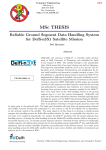
1.2 Operational Characteristics
EHC 105
CRA 211
CPS
CRA 931
DIO Subrack
EHC 105
RIO Subrack
CRP 931
CPS
CPU
EHC 105
Local Subrack
RIO Bus
MB+
MB+
Concept or Modsoft
Figure 1 Typical hardware configuration
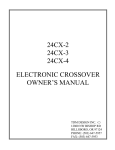
EHC
CPU
Data
State RAM
4xxx
OUT
(13x)
3xxx
IN
(12x)
Exchange
EHC
Program
Parameters (Firmware)
Parameters
The counter module EHC105 needs 13
Out–register (4x...) and 12 In register (3x...) for
configuration.
Figure 2 State RAM diagram as used by the counter
4
Introduction to the EHC 105
20
1.2.1
EHC 105 Counter Channel Principles
Counter 5
{
ÎÎ ÎÎÎÎÎÎÎÎ
ÎÎÎÎÎÎÎÎ
Î
ÎÎÎ
ÎÎ
ÎÎÎÎÎÎÎÎ
ÎÎÎ
Î
ÎÎÎ
ÎÎ
ÎÎÎÎÎÎÎÎ
ÎÎ
ÎÎÎ
ÎÎÎÎÎÎÎÎ
ÎÎ ÎÎÎ
ÎÎ
ÎÎÎ
ÎÎÎ
ÎÎÎÎÎÎÎÎ
ÎÎ
ÎÎÎÎÎÎÎ
ÎÎÎÎÎÎÎÎ
ÎÎÎ
ÎÎÎÎÎÎÎÎ
ÎÎÎÎ
ÎÎÎÎÎÎÎÎ
ÎÎÎÎÎÎÎÎÎÎ
ÎÎÎ
ÎÎÎÎÎÎÎÎÎÎÎ
ÎÎÎ
ÎÎÎÎÎÎÎÎ
ÎÎÎ
ÎÎÎ
ÎÎÎÎÎÎÎÎ
ÎÎ
ÎÎÎ
ÎÎÎ
ÎÎÎÎÎÎÎÎ
ÎÎ ÎÎÎ
ÎÎÎÎÎÎÎÎÎÎ
ÎÎÎ
ÎÎÎ ÎÎÎÎÎÎÎÎÎÎÎ
ÎÎÎ
ÎÎÎÎÎÎÎÎ
Î
VAR
EBUA
Counting Direction
VR1
LS1
C
AND
Load/Start
*)
B
IN2
IN3
IN4
IN5
IN6
IN7
IN8
IN1
OR/
AND
A
AND
OR
D
(SW)
Counter Enable 1
OR
(HW)
24C1
Counting Pulse 1
5C1
Output Set Point 1:
VA11
Set Point 1:
VA1E1
Output Set Point 2:
VA21
Set Point 2:
VA2E1
BEA1
E
Actual Value:
IW
Restart
ST1
F
Counter 1
Operating Mode
Operating Modes 1...B (hex)
Forced Output
Switch–Off
Final Set Point Value:
E/S1
Final Set Point:
E/SE1
OUT1
OUT2
OUT3
OUT4
OUT5
OUT6
OUT7
OUT8
Counter
Watchdog Time:
AND
Counter Input
**)
Timed
Final Set Point:
DE/SE1
Pulse Width:
*) Configurable as either AND or OR. If the gate is not configured the output from
this gate is TRUE.
**) The counting pulse input voltage divider has been schematically simplified
Discrete input signals
State RAM
Discrete output signals
Inversion
Parameters from the Concept/Modsoft configuration dialog
Discrete IN/OUT assignments to the internal counter signals and
possible I/O inversions (through a configuration dialog).
Figure 3 Counter block diagram (counter 1 is depicted)
20
Width: 185 mm
Height: 230 mm
Introduction to the EHC 105
5
1.2.2
IN1 ... 8:
Description of the Individual Signals
Discrete input signals which can be connected and individually inverted to the
counter’s control inputs .
V Each INx signal may be selected several times.
V Every input may be assigned the load/start, restart, or forced Output
switch–off functions.
V Inputs can also be used as counter enable. However in this case the
allocations are defined and may not be changed (i.e. IN1 is allocated
counter 1, IN2 to counter 2, etc.).
V The response times (including firmware scans) are :
h 10 ms for inputs IN1...IN6,
h 5 ms for the IN7 and IN8 inputs.
V Each discrete input can be inverted through the configuration dialogs.
Note: The default is ”Not inverted”. For default assignement refer to page 34,
chapter1.6 Start up characteristics.
24Cx/5Cx (x = 1...5): Discrete inputs for 24/5 VDC counting pulses.
V If the ”Input Signal counts on:” is not selected (”Invert clock” in Concept 2.0)
the counter will count on the ”Neg. Transition”.
V If the selection is made, the counter will count on the ”Pos. Transition”.
Note: The default is ”Neg. Transition”.
VAR:
is a bit within an output register (4x...), which determines if the Output Set
Points will be relative or absolute to Final Set Point Value for all 5 counters.
V ”1” signal: Output Set Point is relative (to the Final Set Point Value)
V ”0” signal: Output Set Point is absolute.
Note: Before configuration, the value is 0.
EBUA:
Is an output register (4x...) bit, which determines module switch–off behavior
for all 5 counters when communication between the controller and EHC 105 is
interrupted.
V ”1” signal: The current output state is retained.
V ”0” signal: All used outputs are set to ”0” level.
6
Introduction to the EHC 105
20
Operating modes 1...B:One of 11 possible operating modes that can be selected for each counter
through a 4x register (Refer to page 31 ore 16).
Note: Before configuration mode is same as mode A. The remaining operating
modes (0, C, D, E, F) are equal to the mode A.
VRx (x = 1...5):
Is a bit within an output register (4x...), which determines the counting direction
of the associated counter. (See also Counting Direction page 14)
”1” signal: Down
”0” signal: Up
Note: Before configuration, the value is 0.
LSx (x = 1...5):
Load/start counter is a bit within an output register (4x...), minimum pulse
width: 3 ms. For more information refer to Figure 4 and Figure 5 on page 12
and 13 Relationship diagrams.
Note: Before configuration, the value is 0.
BEAx (x = 1...5):
Output Switch–Off is a bit within an output register (4x...). The pulse must be
at least 3ms width.
When BEAx is ”1”, it latches the current count in a buffer. While the counter
continues to count, VA1Ex, VA2Ex and E/SEx are reset. This is also true for
any assigned outputs Outx. For more information refer to Figure 4 and
Figure 5 on page 12 and 13 Relationship diagrams.
Note: Before configuration, the value is 0.
STx (x = 1...5):
Counter restart is a bit within an output register (4x...), minimum pulse width:
3 ms.
STx signal releases buffer and counter value of equal current value.
For more information refer to Figure 4 and Figure 5 on page 12 and 13
Relationship diagrams.
Note: Before configuration, the value is 0.
20
Width: 185 mm
Height: 230 mm
Introduction to the EHC 105
7
Counter enable:
These are two enable inputs which have the following functions:
V (SW) counter enable x (x = 1...5): software switch, that enables the counter
and is activated from the Concept/Modsoft configuration screen. In Modsoft
select the option as follow:
h ”Use Input x for counter enable: Yes” : the (HW) counter enable is
effective,
h ”Use Input x for counter enable: No” : the counting pulse is always
enabled.
Note: The default is ”Use Input x for counter enable: No” .
V (HW) counter enable x (x = 1...5): Is a signal that enables the counter, if
”Use Input x for counter enable:” is Yes.
Input channels for this function are predefined. IN1 is allocated to counter 1,
IN2 is allocated to counter 2 etc.
h ”1” signal: counter is enabled (Input not inverted).
h ”0” signal: counter is disabled (Input not inverted).
Note: The default: Input is not selectable for counter enable.
Caution: The pulse counting begins after the first complete pulse
following the counter enable signal. Accordingly, after counting pulse
disable, the next counting pulse will still be registered. As a result during
each count cycle (enable / disable), one pulse will be missing.
Counter Watchdog Timer:This timer monitors incoming pulses and can be enabled throught the
Concept / Modsoft dialog screen:
V Value 0: no monitoring
V Values 1...255: (x 0.1) sec
Note: The default is value 0.
VA1x (x = 1...5):
8
Is the first Output Set Point and can be configured through the Concept /
Modsoft dialog screen.
Value range: 0...(2 exp31) –1
Introduction to the EHC 105
20
Note: The default is value 0.
If relative Output Set Point mode is selected, output Set Point Values are
relative to the Final Set Point Value.
Requirement for that: E/S > VA1 >= VA2 >= 0.
If absolute Output Set Point mode is selected, this value is absolute.
Requirements for that: E/S > VA2 >= VA1 >= 0.
VA1Ex (x = 1...5):
Is a bit within an input register (3x...).
This may be assigned through the Concept / Modsoft dialog screen to any
of the discrete outputs OUT1...OUT8.
Note: Before configuration, the value is 0. For default assignement refer to
page 34, chapter1.6 Start up characteristics.
VA2x (x = 1...5):
Is the second Output Set Point and can be configured through the the Concept
/ Modsoft dialog screens.
Value range: 0...(2 exp31) –1
Note: The default is value 0.
If relative Output Set Point mode is selected, output Set Point Values are
relative to the Final Set Point Value.
Requirement for that: E/S > VA1 >= VA2 >= 0.
If absolute Output Set Point mode is selected, this value is absolute.
Requirements for that: E/S > VA2 >= VA1 >= 0.
VA2Ex (x = 1...5):
Is a bit within an input register (3x...).
This may be assigned through the Concept / Modsoft dialog screen to any
of the discrete outputs OUT1...OUT8.
Note: The default assignement refer to page 34, chapter1.6 Start up
characteristics.
E/Sx (x = 1...5):
Is an output register (4x...) in which the counter’s final (up counter) or inital
(down counter) is entered.
Value range: 0...(2 exp31) –1
Note: Before configuration, the value is 0.
E/SEx (x = 1...5):
20
Width: 185 mm
Height: 230 mm
Final Set Point is a bit within an input register (3x...).
Introduction to the EHC 105
9
This may be assigned through the Concept / Modsoft dialog screen to any
of the discrete outputs OUT1...OUT8.
Note: Before configuration, the value is 0. For default assignement refer to
page 34, chapter1.6 Start up characteristics.
DE/SEx (x = 1...5):
The Timed Final Set Point, settable through the Concept / Modsoft dialog
screen:
This may be assigned through the Concept / Modsoft dialog screen to any
of the discrete outputs OUT1...OUT8.
Note: Before configuration, the value is 0. The default assignement is: No
assignement.
Pulse width:
This defines the length of the Timed Final Set Point pulse. In addition, in
operating mode A, this defines the time for all associated outputs.
Value 0: output DE/SEx is disabled
Values 1...255: (x 0.02) sec.
Note: The default value is 0.
STOP
OUT1...8:
Warning: If in operating mode A, this value equal ”0” there will be no
outputs.
Discrete output signals, which can be assigned and individually inverted to the
counter outputs VA1E (Set Point 1), VA2E (Set Point 2), E/SE (Final Set
Point), and DE/SE (Timed Final Set Point).
Note: The default: outputs are not inverted. The default assignment refer to
page 34, chapter1.6 Start up characteristics.
STOP
10
Warning: Do not select the same output OUT1 ... OUT8 with more than
one Set Point. Even if Modsoft allowed you to do that, such multiple use is
prohibited. Such double assignments lead to unpredictable process
states, and are particularly difficult to diagnose.
Introduction to the EHC 105
20
1.2.3
Output Set Point Mode (Absolute, Relative)
The Output Set Point is configured once for all module counters.
The module operates in absolute or relative Output Set Point Mode.
1.2.3.1
Absolute Output Set Point Mode
In this mode, the value entered in the Concept / Modsoft screen is the actual
Output Set Point.
1.2.3.2
Relative Output Set Point Mode
In this mode, the Output Set Point is the difference between the entered value in
the Concept / Modsoft screen and the Final Set Point Value.
1.2.4
Start and Stop Function Priority Rankings
The prioritazing of signals to start or stop a counter is as follow:
Priority 1
Forced Output Switch–Off, active for BEAx = ”1” (state RAM) OR one of the
configured discrete inputs as ”1”.
Priority 2
Load/start counter, active for LSx = ”1” (state RAM) AND a TRUE evaluation
of the configured discrete inputs.
Priority 3
Restart counter, active for STx = ”1” (state RAM) AND a TRUE evaluation of
the configured discrete inputs.
Note: The user program commands are necessary for starting and restarting
of the counting procedures. Setting of the corresponding discrete inputs is also
required. When no discrete input is assigned to the commands through
”Load/Start and Restart”, the counting procedure is initiated through the output
status word (4x...) bits LSx resp. STx.
20
Width: 185 mm
Height: 230 mm
Introduction to the EHC 105
11
1.2.4.1
Relationship Diagrams of LS1, ST1, and BEA1 for Counter 1
Without hardware input configuration (Load/Start, Restart,
Output–Switch–Off and Counter Enable).
Pulse Input
Signal
Counter Input 1
LS1
BEA1
ST1
Actual Value IW
E/S Value
VA2 Value
Counter
Actual Value
VA1 Value
0
VA1E1
Counter
Outputs
(if configured)
VA2E1
E/SE1
DE/SE1
DE/SE1 pulse width can be specified in the Concept/Modsoft configuration screen.
Figure 4 Counter 1 diagram as event counter, parallel, absolute, output function non inverted and counting up
LS1: With the rising edge from LS1, the actual counting value is set to 0. The
outputs VA1E1, VA2E1 and E/SE1 are set to ”1” signal for the operation mode 1
... 5 and 8,9 or to ”0” signal for operation mode A and B.
BEA1 / ST1: With a ”1” signal at BEA1 the actual value will latch; the counting
continues in an internal memory of the module. Is there on BEA1 a ”0” signal
the counting of the actual value continues with the current contents of the
memory. Is there on ST1 a rising edge the outputs switche on depended from
the actuale value.
12
Introduction to the EHC 105
20
With hardware input configuration (Load/Start, Restart,
Output–Switch–Off and Counter Enable).
Pulse Input
Signal
Counter Input 1
(HW) Counter Enable (IN1)
not inverted
Load/Start or Restart (IN6)
not inverted
LS1
BEA1
ST1
Output Switch–Off (IN8)
not inverted
Actual Value IW
E/S Value
VA2 Value
Counter
Actual Value
VA1 Value
0
VA1E1
Counter
Outputs
(if configured)
VA2E1
E/SE1
DE/SE1
DE/SE1 pulse width can be specified in the Concept/Modsoft configuration dialogs
Figure 5 Counter 1 diagram as event counter, parallel, absolute, with output function non inverted and counting up
Note: The discrete input evaluation for ”Load/Start or Restart” is AND’ed with
the LSx resp. STx signal. The LSx and STx signals operate edge–controlled.
Note: The ”Output Switch–Off” discrete inputs have the same function as the
BEAx bit.
The AND condition is true should there have been no configuration carried out
for ”Load/Start or Restart”; the LSx and STx bits then function alone.
If the discrete input is not inverted, the High signal is active (see figure above).
If discrete input is inverted, the Low signal is active.
LSx and STx bit are always active with the rising ege, it can not be inverted.
20
Width: 185 mm
Height: 230 mm
Introduction to the EHC 105
13
BEAx is always active with the High signal, it can not be inverted.
An active BEA signal set all inverted outputs to a High signal.
If the Outputs are inverted, the state from the signals VA1Ex, VA2Ex and E/SEx
will not inverted.
1.2.5
Counting Direction Determination
The individual counters can function as bidirectional counters, counting up or
down. The counting direction is specified by output status word (4x...) bit VR.
VRx = ”0”: Up–counter, starting with 0, stop at final value E/S.
VRx = ”1”: Down–counter, starting at initial value E/S, stop at 0
Note: Do not change the value of the VRx bit during operation of the counter.
If the value changes, the associated outputs of the counter will be switched off.
14
Introduction to the EHC 105
20
1.2.6
Overview and Relationships of Counter Functionality
Features
Down
Settings overview
Per Module
Per Counter
1
BA = A
BA=operating mode (hex)
Event/Timed
VR =
0
1
BA = 1
VR =
Event/Parallel
0
1
Relative mode
BA = 8
Event/parallel/fast *)
VR =
0
1
Outputs Remain
BA = 2
VR =
1
VAR =
1
0
1
EBUA =
0
BA = 9
VR =
Event/Serial/Fast *)
0
1
VAR =
0
Event/Serial
0
1
BA = B
VR =
Event/Latched
0
1
Outputs
Switch Off
BA = 3
VR =
Differential/Parallel
0
1
Absolute mode
BA = 4
Differential/Serial
VR =
0
1
BA = 5
EBUA and VAR selection have no effect to this
type of counter in operating modes 6 and 7.
1
BA = 6
Repetitive
0
Up
Rate Counter 100ms
VR =
0
1
BA = 7
VR =
*) Fast counters have no
restart function
Rate Counter 1sec
VR =
0
Figure 6 Possible counter settings
20
Width: 185 mm
Height: 230 mm
Introduction to the EHC 105
15
1.3 EHC 105 Counter Types
The EHC 105 module can operate as:
Event counter (with and without fast Final Set Point)
Event counter with Timed or latched outputs
Differential counter (without fast Final Set Point)
Repetitive counter (with fast Final Set Point)
Rate counter
The selection of the various counter types takes place through the operating
mode selections in state RAM. Every counter type can count up and down.
Output Set Point Mode can be set to be relative (to the Final Set Point Value) or
absolute.
Note: For an active counter, any change of the operating mode or counting
direction, switch–off behavior, or type of Set Point triggers an Output
Switch–Off. A change of the operating mode accompanied by load/start is not
possible. (The setting of the load / start bit after changing the operation mode
must be done in the next scan cycle.)
Note: Discrete Output Signal Response Times:
Without fast Final Set Point: typically 3 ms.
With fast Final Set Point: typically 0.5 ms.
Table 1
16
Counter Operating modes
Value (hex)
Meaning
1
Event counter with parallel Set Point activations
2
Event counter with serial Set Point activations
3
Differential counter with parallel Set Point activations (only applies to counters 1
and 3, the Set Point and actual values of counters 2 resp. 4 are inactive)
4
Differential counter with serial Set Point activations (only applies to counters 1
and 3, the Set Point and actual values of counters 2 resp. 4 are inactive)
5
Repetitive counter
6
Rate counter, gate time t = 100 ms
7
Rate counter, gate time t = 1 s
8
Event counter with parallel Set Point activations and fast Final Set Point
9
Event counter with serial Set Point activations and fast Final Set Point
A
(default)
Event counter with timed ”on” outputs, the pulse width setting holds for all employed outputs.
Introduction to the EHC 105
20
Table 1
1.3.1
Counter Operating modes
Value (hex)
Meaning
B
Event counter with latched Set Point outputs.
0, C, D, E, F
as operating mode A
The Event Counter
The event counter is a gate–controlled, bidirectional counter with two or less
Set Points, a Final Set Point and a Timed Final Set Point. It utilizes six different
operating modes. See also Table 5 on page 31.
V Operating mode A: with adjustable ”time on” outputs
h The pulse width configuration applies the same value to all counter
outputs. Outputs are at ”0” signal on start.
V Operating mode 1: with parallel Output Set Point activation
V Operating mode 2: with serial Output Set Point activation
V Operating mode 8: with parallel Output Set Point activation and
fast Final Set Point
V Operating mode 9: with serial Output Set Point activation and
fast Final Set Point
V Operating mode B: with latched Set Point activation
Outputs are at ”0” signal on start.
The value range for all operating modes amounts to: 0...(2 exp 31) – 1, except
the operating mode 5 is 0...(2 exp 16) –1.
20
Width: 185 mm
Height: 230 mm
Introduction to the EHC 105
17
1.3.1.1
Operating modes 1 and 8 (Event counter with relative Output Set Point
Value and parallel Set Point activation)
Pulse Input
Signal
Counter Input
LS
(HW) Counter Enable (IN1)
Actual Value IW
E/S Value
Counter
Actual Value
Value from E/S–VA2
Value from E/S–VA1
0
VA1E
Counter
Outputs
(if configured)
VA2E
E/SE
DE/SE
DE/SE pulse width can be specified in the Concept/Modsoft dialog screen
Figure 7 Counting up (VR = 0)
Pulse Input
Signal
Counter Input
LS
(HW) Counter Enable (IN1)
Actual Value IW
E/S Value
Counter
Actual Value
VA1 Value
VA2 Value
0
VA1E
Counter
Outputs
(if configured)
VA2E
E/SE
DE/SE
DE/SE pulse width can be specified in the Concept/Modsoft dialog screen
Figure 8 Counting down (VR = 1)
18
Introduction to the EHC 105
20
1.3.1.2
Operating modes 2 and 9 (Event counter with relative Output Set Point
Value and serial Set Point activation)
Pulse Input
Signal
Counter Input
LS
(HW) Counter Enable (IN1)
Actual Value IW
E/S Value
Counter
Actual Value
Value from E/S–VA2
Value from E/E–VA1
0
VA1E
Counter
Outputs
(if configured)
VA2E
E/SE
DE/SE
DE/SE pulse width can be specified in the Concept/Modsoft dialog screen
Figure 9 Counting up (VR = 0)
Figure 7 to Figure 9 Event counter with relative and parallel and serial Set Point
activation are typical time diagrams.
That do no take into account the following signals:
BEAx Further information you will find on page 12
STx Further information you will find on page 12
Note: STx has no function in the operating modes 8 and 9.
20
Width: 185 mm
Height: 230 mm
Introduction to the EHC 105
19
1.3.1.3
Operation mode A (Event counter with absolute Output Set Point Value
and timed output activation)
Pulse Input
Signal
Counter Input
LS
(HW) Counter Enable (IN1)
Actual Value IW
E/S Value
Counter
Actual Value
VA2
VA1
0
(VA1E) OUTx
Counter
Outputs
(VA2E) OUTy
(E/SE) OUTz
DE/SE
VA1E
Register bits
VA2E
E/SE
A common pulse width for all outputs can be specified in the Concept/Modsoft dialog screens
Figure 10 Counting up (VR = ”0”)
Note: The activation of the discrete outputs are different from the activation of
the register bits.
20
Introduction to the EHC 105
20
1.3.1.4
Operation–mode B (Event counter with absolute Output Set Point Value
and latched output activation)
Pulse Input
Signal
Counter Input
LS
BEA
(HW) Counter Enable (IN1)
Actual Value IW
E/S Value
Counter
Actual Value
VA2
VA1
0
(VA1E) OUTx
Counter
Outputs
(VA2E) OUTy
(E/SE) OUTz
DE/SE
VA1E
Register bits
VA2E
E/SE
DE/SE pulse width can be specified in the Concept/Modsoft dialog screen
Figure 11 Counting up (VR = 0)
Note: The activation of the discrete outputs are different from the activation of
the register bits.
20
Width: 185 mm
Height: 230 mm
Introduction to the EHC 105
21
1.3.2
The Differential Counter
The differential counter is a gate–controlled counter with up to two Output Set
Points, a Final Set Point and a Timed Final Set Point. A differential counter
consists of two counter channels and meassures the difference of each of their
pulses. It is equipped with two different operating modes:
V Operating mode 3: with parallel Set Point activation
V Operating mode 4: with serial Set Point activation
Counter 1 (clockwise) and 2 (counterclockwise) form a differential counter 1,
while counter 3 (clockwise) and 4 (counterclockwise) form a differential counter
2. This configuration cannot be changed.
The counting value is determined from the difference of the two counters.
Differential counter configuration, control and evaluation is done through the
parameters and values of the first counter with the exception of the counter
input.
The configuration for the respective second counter must be performed
separately. The parameter choices (from the Modsoft / Concept dialog screen)
are:
V Invert Counter Input / Input Signal counts on.
V Use Input for Counter enable / Input for Counter enable.
Note: A fast Final Set Point cannot be set for differential counters. If a counter
is disabled, counter time monitoring is suspended.
V The value ranges are as follows:
h Set Point values: 0...(2 exp 30) –1
h Actual values: –(2 exp 30)...(2 exp 30) –1
Note: The value range allows the differential counter to also be used for
continuous monitoring.
22
Introduction to the EHC 105
20
1.3.2.1
Operating mode 3 (Differential counter with relative Output Set Point Value
and parallel output activation)
Pulse Input Signal
Counter Input 1/3
Counter Input 2/4
Pulse Input Signal
LS
Differential current value
E/S value
Counter
Actual Value
Value from E/S – VA2
Value from E/S – VA1
0
VA1E
Counter
Outputs
(if configured)
VA2E
E/SE
DE/SE
DE/SE pulse width can be specified in the Concept/Modsoft dialog screen
Figure 12 Differential counter with parallel output activation counts up (VR = 0)
20
Width: 185 mm
Height: 230 mm
Introduction to the EHC 105
23
Continuation Operating Mode 3 (Differential counter with relative
Output Set Point Value and parallel output activation)
Pulse Input Signal
Counter Input 1/3
Counter Input 2/4
Pulse Input Signal
LS
Differential current value
E/S value
VA1 value
Counter
Actual Value
Va2 value
0
VA1E
Counter
Outputs
(if configured)
VA2E
E/SE
DE/SE
DE/SE pulse width can be specified in the Concept/Modsoft dialog screen
Figure 13 Differntial counter with parallel output activation counts down (VR = 1)
Figure 12 and Figure 13 ”Differential counter with parallel set–point cutoffs (VR
= 0)” are typical timing diagram that do not take into account the following
signals:
BEAx Further information you will find on page 12
STx Further information you will find on page 12
24
Introduction to the EHC 105
20
1.3.2.2
Operating mode 4 (Differential counter with relative Output Set Point Value
and serial output activation)
Pulse Input Signal
Counter Input 1/3
Counter Input 2/4
Pulse Input Signal
LS
Differential current value
E/S value
Counter
Actual Value
Value from E/S – VA2
Value from E/S – VA1
0
VA1E
Counter
Outputs
(if configured)
VA2E
E/SE
DE/SE
DE/SE pulse width can be specified in the Concept/Modsoft dialog screen
Figure 14 Differential counter with serial output activation counts up (VR = 0)
Figure 14 ”Differential counter with serial set–point cutoffs” is a typical timing
diagram that do not take into the following signals:
BEAxFurther information you will find on page 12
STxFurther information you will find on page 12
20
Width: 185 mm
Height: 230 mm
Introduction to the EHC 105
25
1.3.3
The Repetitive Counter (Operating mode 5)
The repetitive counter is an up / down counter with up to two Output Set Points,
a fast Final Set Point, which acts as a third Set Point and a Timed Final Set
Point.
Operating Mode 5: with serial output activation
As a repetitive counter, every time the Final Set Point value is reached, the
following restrictions apply:
E/Sx values are limited to the value ranges 0...(2 exp 16) –1.
The Final Set Point value cannot be changed when the counter is active.
BEA must be set in advance.
The Final Set Point Value must be equal or greather than 2.
Pulse Input
Signal
Counter Input
LS
Actual Value IW
E/S Value
VA2 Value
Counter
Actual Value
VA1 Value
0
VA1E
Counter
Outputs
VA2E
(if configured)
E/SE
DE/SE
DE/SE pulse width can be specified in the Concept/Modsoft dialog screen
Figure 15 Repetitive counter with serial output activation
Figure 15 ”Repetitive counter” is a typical timing diagram that does not take into
account the following signal:
BEAxFurther information you will find on page 12
STx has no effect in this operating mode refer to page 12 for further
information
26
Introduction to the EHC 105
20
1.3.4
The Rate Counter (Operating mode 6 or 7)
The rate counter counts the number of pulses per unit time. A unit time is
specified with the choice of the operating modes 6 or 7. The read value is then
saved as the actual value.
The determined actual value thus represents the pulse count per unit time, and
can be used to determine velocities, flow rates, or even revolutions.
Inputs and outputs are not processed in this counter type.
THe Watchdog timer function is not supported.
There are two operating modes for the rate counter. These differ only in the
prescribed internal gate time.
Operating mode 6: The gate time t amounts to 100 ms
Operating mode 7: The gate time t amounts to 1 s
20
Width: 185 mm
Height: 230 mm
Introduction to the EHC 105
27
1.4 State RAM Structure
1.4.1
Input Structure
Table 2
State RAM input structure (EHC 105 –> CPU ), word addressing
3x Registers
Relative Address
Content
3x
000
Input Status Word 1
3x+1
001
3x+2
002
3x+3
3x+4
004
3x+5
3x+6
006
3x+7
3x+8
008
3x+9
3x+10
010
3x+11
Input Status Word 2
Low Word
Counter 1
High Word
Actual Value
Low Word
Counter 2
High Word
Actual Value
Low Word
Counter 3
High Word
Actual Value
Low Word
Counter 4
High Word
Actual Value
Low Word
Counter 5
High Word
Actual Value
Quantum local drop:
The relative address relates to the Concept configuration ”In Ref” address,
refer to Configuration Steps in chapter 2.2.2.1, page 39.
Modsoft Configuration:
The relative address relates to the Modsoft configuration ”Input Ref” address,
refer to Configuration Steps, chapter 2.2.3.1, page 42.
Note: Counter actual values are shown as decimal values: in Concept as Dec
(signed 32–bit); in Modsoft as Long Dec (unsigned 32–bit) for CPU Exec 2.0
and greather. This means that negative values can not be displayed correctly.
28
Introduction to the EHC 105
20
Input Status Word 1
Bit
15
14
13
3x
12
11
10
9
8
7
E/SE5 E/SE4 E/SE3 E/SE2 E/SE1 US24
6
SC
5
INDI–
CATE
4
3
2
1
0
ERR5 ERR4 ERR3 ERR2 ERR1
MSB
LSB
Input Status Word 2
Bit
15
14
13
12
11
10
9
8
7
6
5
VA2E5 VA2E4 VA2E3 VA2E2 VA2E1
3x+1
4
3
2
1
0
VA1E5 VA1E4 VA1E3 VA1E2 VA1E1
MSB
LSB
MSB = most significant bit
LSB = least significant bit
Table 3
Signal
Input status word signal explanations
Value
Meaning
Input Status Word 1
ERRx
1
Error in counter x (specified by Indicate, i.e. bit 5 in status word 1)
INDICATE
0
Counter overflow (actual value > 2 exp (16), 2 exp (30) resp. 2 exp (31)–1)
1
Counting pulse error (counter timeout value expired)
SC
1
Discrete output short circuit or overload
US24
1
External power failure (discrete outputs)
E/SEx
1
Final set point signal on counter x is 1 Signal
Input Status Word 2
VA1Ex
1
First Set Point signal on counter x is a 1 Signal
VA2Ex
1
Second Set Point signal on counter x is a 1 Signal
Note: Output inversions (E/SEx, VA1Ex, VA2Ex) are not used on the
corresponding bits in status words 1 and 2.
20
Width: 185 mm
Height: 230 mm
Introduction to the EHC 105
29
1.4.2
Output Structure
Table 4
State RAM output structure (CPU –> EHC 105), word addressing
4x Register
Relative
Address
Content
4x
000
Output Control Word 1
4x+1
001
Output Control Word 2
4x+2
002
Output Control Word 3
4x+3
003
Counter 1
4x+4
Low Word
Stop value
for VR1 = ”0”, Final Set Point Value E/S1
High Word
Initial value
for VR1 = ”1”, Final Set Point Value E/S1
Counter 2
4x+5
005
4x+6
Low Word
Stop value
for VR2 = ”0”, Final Set Point Value E/S2
High Word
Initial value
for VR2 = ”1”, Final Set Point Value E/S2
Counter 3
4x+7
007
4x+8
Low Word
Stop value
for VR3 = ”0”, Final Set Point Value E/S3
High Word
Initial value
for VR3 = ”1”, Final Set Point Value E/S3
Counter 4
4x+9
009
4x+10
Low Word
Stop value
for VR4 = ”0”, Final Set Point Value E/S4
High Word
Initial value
for VR4 = ”1”, Final Set Point Value E/S4
Counter 5
4x+11
011
4x+12
Low Word
Stop value
for VR5 = ”0”, Final Set Point Value E/S5
High Word
Initial value
for VR5 = ”1”, Final Set Point Value E/S5
Quantum local drop: The relative address relates to the Concept configuration
”Out Ref” address, refer to (Configuration Steps chapter 2.2.2.1, page 39).
Modsoft Configuration: The relative address relates to the Modsoft configuration
”Output Ref” address, (refer to Configuration Steps, chapter 2.2.3.1, page 42).
30
Introduction to the EHC 105
20
Output Control Word 1
Bit
15
4x
14
13
12
11
Counter 1 Operating Mode VR1
10
BEA1
9
8
ST1
LS1
7
6
5
4
3
2
EBUA VAR
1
0
FQ
Q
MSB
LSB
Output Control Word 2
Bit
15
4x+1
14
13
12
11
Counter 3 Operating Mode VR3
10
BEA3
9
8
ST3
LS3
7
6
5
4
3
Counter 2 Operating Mode VR2
2
1
0
BEA2
ST2
LS2
MSB
LSB
Output Control Word 3
Bit
15
4x+2
14
13
12
11
Counter 5 Operating Mode VR5
10
BEA5
9
8
ST5
LS5
7
6
5
4
3
Counter 4 Operating Mode VR4
2
1
0
BEA4
ST4
LS4
MSB
LSB
MSB = most significant bit
LSB = least significant bit
Table 5
Signal
Value (hex)
Meaning
Counter x Operating Mode
1
Event counter with parallel Set Point activations
2
Event counter with serial Set Point activations
3
Differential counter with parallel Set Point activations (only
applies to counters 1 and 3, the Set Point and actual values
of counters 2 resp. 4 are inactive)
4
Differential counter with serial Set Point activations (only
applies to counters 1 and 3, the Set Point and actual values
of counters 2 resp. 4 are inactive)
5
Repetitive counter
6
Rate counter, gate time t = 100 ms
7
Rate counter, gate time t = 1 s
8
Event counter with parallel Set Point activations and fast
Final Set Point
9
Event counter with serial Set Point activations and fast Final
Set Point
A
(default)
Event counter with timed ”on” outputs, the pulse width setting holds for all employed outputs.
B
Event counter with latched Set Point outputs.
0, C, D, E, F
as operating modes A
0
Counter x counts up
1
Counter x counts down
BEAx
1
Counter x Output Switch–Off
STx
1
Counter x restart (controlled by rising edge)
LSx
1
Counter x load/start (controlled by rising edge)
EBUA
1
Outputs retain their current state on communication errors
0
Outputs go to ”0” signal on communication errors
VRx
20
Width: 185 mm
Height: 230 mm
Output control word signal explanations
Introduction to the EHC 105
31
Table 5
Output control word signal explanations
Signal
Value (hex)
Meaning
VAR
1
Output Set Points (values) are relative for all counters
0
Output Set Points (values) are absolute for all counters
Q
1
Acknowledgement for all counter channels after an output
short circuit fault signal (SC). (The red LED (F) extinguishes).
FQ
1
Acknowledgement after power failure and counter errors
(ERR1...ERR5 and Indicate). (The red LED (F) extinguishes). If several errors are present, they must be acknowledged individually one after the other.
Caution: If the counter’s operating mode, counting direction, switch–off
behavior, or type of Set Point are changed while the counter’s output
signals are active, the output will be deactivated and the new changes will
take effect.
32
Introduction to the EHC 105
20
1.5 Monitoring Capabilities
1.5.1
Input Signal Monitoring
The EHC 105 can monitor the presence or absence of incoming signals. To
activate signal monitoring, it is necessary to state a value between 1 and 255 in
the Concept / Modsoft dialog screen for ”Clock/Counter Watchdog Time”. This
fixes the counter’s watchdog timers within the limits from 100 ms to 25.5 s. No
monitoring is performed for 0 values.
If a pulse is not detected at the respective input of a running counter within the
declared timeout interval, then the transmitter error flag (INDICATE) is changed
to ”1” and the corresponding error bit (ERR) is on, triggering a Forced Output
Switch–Off and ”F” LED is ON.
Counting pulse monitoring for the respective counter occurs when the counting
pulse is enabled and the counter is running. The prerequisite is the specification
of a watchdog timer: (Refer to page 6ff)
Note: Count pulse monitoring is not supported in operating modes 6 and 7.
Refer to chapter 1.3.2, page 22 differential counters.
1.5.2
Quantum System Bus Monitoring
A ”system active” signal is activated on the Quantum system bus. If the CPU
fails, all outputs are set accordingly and the green ACTIVE status LED turns off.
The status of the outputs in the event of a communication failure between the
controller and the EHC 105 can be selected through the EBUA output register
bit (4x...).
V ”1” signal: The current output state is retained.
V ”0” signal: All employed outputs are set to ”0” level.
1.5.3
US24 Power Monitoring
If the external 24VDC power supply fails during operation, the green ”P” LED
turns off and is shown in the module status byte and the red ”F” LED turns on.
If the power goes on again, the ”P” LED turns on and the ”F” LED turns off.
An Output Switch–Off is not triggered for a running counter.
The discrete output (OUT1...OUT8) status displays (1" to 8") turn off
(independent from the defined output logic).
20
Width: 185 mm
Height: 230 mm
Introduction to the EHC 105
33
1.6 EHC 105 Start–Up Characteristics
At EHC 105 start–up, all actual values are cleared to 0, outputs are deactivated
(i.e. VA1E=VA2E=E/SE =”0”) and the counters are defaulted to up–event
counters, with absolute Output Set Point Values (VAR = ”0”) and outputs in
timed control mode (operating mode A).
Outputs are set to ”0” (EBUA = ”0”) on controller communications failure with
the EHC105.
By default, all counters are enabled.
Table 6
Start–up assignments for discrete I/O
Counter Input/Output
Discrete Signal
Pin Assignments
Counter 1
LS1
(Load and Start)
IN1
21
ST1
(Restart)
IN1
21
BEA1 (Output Switch–Off)
IN6
26
Counting Pulse 1
5C1/24C1
1/11
VA2E1
OUT6
36
E/SE1
OUT1
31
Counter 2
LS2
(Load and Start)
IN2
22
ST2
(Restart)
IN2
22
Counting Pulse 2
5C2/24C2
3/13
E/SE2
OUT2
32
Counter 3
LS3
(Load and Start)
IN3
23
ST3
(Restart)
IN3
23
BEA3
IN7
27
Counting Pulse 3
5C3/24C3
5/15
VA2E3
OUT7
37
E/SE3
OUT3
33
Counter 4
34
LS4
(Load and Start)
IN4
24
ST4
(Restart)
IN4
24
Counting Pulse 4
5C4/24C4
7/17
E/SE4
OUT4
34
Introduction to the EHC 105
20
Table 6
Start–up assignments for discrete I/O
Counter Input/Output
Discrete Signal
Pin Assignments
Counter 5
20
Width: 185 mm
Height: 230 mm
LS5
(Load and Start)
IN5
25
ST5
(Restart)
IN5
25
Counting Pulse 5
5C5/24C5
9/19
BEA5
IN8
28
VA2E5
OUT8
38
E/SE5
OUT5
35
Introduction to the EHC 105
35
36
Introduction to the EHC 105
20
Chapter 2
Configuration
Hardware and Software Prerequisites
Configuration Steps
20
Width: 185 mm
Height: 230 mm
Configuration
37
2.1 Hardware and Software Prerequisites
PC for Concept / Modsoft
Software package: Concept version 2.0 or Modsoft version 2.4
CPU EXEC ≥ version 2.0
Quantum System with any CPU refer to ”Quantum Reference Guide
(840 USE 100 00)”
Note: Althought, this module is also supported with Modsoft 2.32, version 2.4
or greater is required. The screens, described in this document come from
version 2.4.
This module is also supported with Concept 1.13, but we recommand to use
version 2.0 or greater. The screens, described in this document come from
version 2.0.
2.2 Configuration Steps
The steps necessary for configuration are presented here. Where additional
information is necessary, references to the corresponding documentation is
made.
2.2.1
Configuration Steps for Installation
Configure your controller in accordance with your requirements, also with
respect to the EHC 105, as described in the ”Quantum Hardware Reference
Guide (840 USE 100 00)”. Details for connecting signal transmitters to the
EHC 105 can be found within the module description in the appendix A
(Module Description).
Plan and carry out the module cabling in accordance with the module
details (i.e. cable routing, shielding etc.).
Log your terminal assignment plan on the label inlay inside the module I/O
block cover.
38
Configuration
20
2.2.2
2.2.2.1
Configuration using Concept ( 2.0)
Drop configuration (slot and I/O map)
Local Quantum Drop
Drop
Modules: 5
Status Table:
Clear
Prev
Slot
1
2
3
4
5
6
7
8
9
10
11
12
13
Next
Module
CPS 214 00
CPU x13 0x
DDI 353
... 00
DDO 353 00
...
...
...
EHC 105 00
...
...
...
...
...
OK
Module
Bits In: 192 Bits Out: 208
Delete
Params...
Bits In: 224Bits Out: 240
ASCII Port#:
none
Detected
Cute
In Ref
In End
Copy
Out Ref
Paste
Out End
000001 000032
Descrip
DC PS 24V
CPU 1xMB
DC IN 24V
DC OUT 2
400001 400013
HIGH SPEED
100001 100032
300001 300012
Cancel
Poll
Help
Figure 16 Configuration using Concept
Table 7
20
Width: 185 mm
Height: 230 mm
Drop editor terminology explanations (see above)
Term
Meaning
Clear (Drop)
Configuration deletion for all slot resident modules
Delete (Module)
Deletion of the selected module
Params...
Starts the configuration dialog
Slot
Selects the slot for module entry
Module
Starts the module configuration dialog
Detected
Modules recognized on–line
In Ref
State RAM initial address (for input)
In End
State RAM calculated end address (for input)
Out Ref
State RAM initial address (for output)
Out End
State RAM calculated end address (for output)
Description
Short module description
OK
Accepts all inputs
(see next screen)
Configuration
39
2.2.2.2
Configuration of counter characteristics under Concept
The following EHC 105 settings are selected with the Concept dialog screen:
140 EHC 105 00
Inversion of Inputs
No. 1
No. 2
No. 3
No. 4
No. 5
No. 6
No. 7
No. 8
Counter
Outputs
Counter: 1
Preceded Signal 1
Invert Clock
Input No. 1 for Clock Enable
Clock Watchdog Time (x 0.1s):
Output No: 1
Invert
0
Preceded Signal 2
Preceded Setpoint
Output No: 2
Value 1: 11
Invert
Value 2: 5
Final Signal
Inputs
Load/Start or Restart
Output No: 3
Logic Between Start Inputs
Input No: 6
Input No: –
OR
Invert
Dynamic Final Signal
Invert
Input No: –
Output No: 4
Input No: –
Pulse Width (x 0.02 s): 20
Outputs Switch–Off
Input No: 8
Input No: –
OK
Cancel
Help
Figure 17 Concept dialog screen (counter 1 example)
Table 8
40
Configuration
Quantum I/O map terminology explanations
Term
Meaning
Inversion of Inputs
Select inversion of all discrete inputs (IN1...IN8)
Counter
Selection of the individual counters
Invert Clock
Select inversion of the counter inputs
Input No. 1 for Clock
Enable
Select Input 1 to enable counter.
Clock Watchdog Time (x
0.1s):
Counter Watchdog time setting in 0.1s steps,
0 disables counting pulse monitoring
Preceded Setpoint
–Relative
If relative Output Set Point mode is selected, output Set Point Values
are relative to the Final Set Point Value.
Requirement for that: E/S > VA1 >= VA2 >= 0.
–Absolute
If absolute Output Set Point mode is selected, this value is absolute.
Requirements for that: E/S > VA2 >= VA1 >= 0.
Logic Between Start Inputs
Logic function among inputs to Load / Start or Restart the counter.
Input No:
Assignment of up to 3 process inputs for load/start and restart function
control.
Outputs Switch Off
Assignment of up to 3 process inputs to Output Switch–Off
Preceded Signal 1
Assignment (and optional inversion) of a discrete output to the first
set–point.
20
Table 8
20
Width: 185 mm
Height: 230 mm
Quantum I/O map terminology explanations
Term
Meaning
Preceded Signal 2
Assignment (and optional inversion) of a discrete output to the second
set–point.
Final Signal
Assignment (and optional inversion) of a discrete output to the final
set–point.
Dynamic Final Signal
Assignment (and optional inversion) of a discrete output to the timed
final set–point
Pulse Width (x 0.02s):
Setting of the Dynamic Final Signal pulse width (0...255).
0 disables the output.
Configuration
41
2.2.3
2.2.3.1
Configuration under Modsoft ( 2.4)
I / O Map screen
""%
!!
!" !
#"
$ QUANTUM I/O MAP
Type: Local I/O
Head–Slot: 0
Drop: 1
Available: 444
Drop Hold Up Time : 3 x100ms
Module Status Reg: 0
Number of Inputs : 192
Number of Outputs : 208
Slot
Module
Input Ref
Output Ref
Description
101
102
103
104
105
106
107
EHC 105 00
108
300100–300111 400100–400112 High Speed CTR 5CH
109
110
111
112
113
114
115
116
Figure 18 Configuration under Modsoft
Table 9
42
Configuration
Quantum I/O map terminology explanations (see above)
Term
Meaning
F3 ClrDrop
Configuration deletion for all slot resident modules
Slot
Displays the slot for module entry
Module
Starts the module configuration dialog
Input Ref
State RAM initial address (for input)
Output Ref
State RAM initial address (for output)
Description
Short module description
20
2.2.3.2
Configuration of counter characteristics under Modsoft
The following EHC 105 settings are selected with the Modsoft configuration
dialog, (the configuration dialog consists of 10 screen pages, an input and an
output page per counter):
For Inputs
Hex
F1
Bin
GoTo
Quit
F4 I / O Map
F5 Module
F6Editor F7-Lev 8-F8-OFF
F9
140 EHC 105 00: HIGH SPEED COUNTER, 5 Chan Screen 1 of 10
COUNTER 1
Head Slot: 0 Drop: 1
Slot: 8
INPUTS:. . .
(next screen for counter 1 output settings)
Input Signal counts on: Neg Transition Use Input 1 for Counter enable: No
F2
Dec
F3
Counter 1 Watchdog Time = 0
DEC
(*0.1sec.)
Output Setpoint 1, Value 1= 0
DEC
Output Setpoint 2, Value 2= 0
DEC
Counter Starts or Restarts . . .
Input A: 1
Input B:NONE
Input C: NONE
Logic function for inputs to START / RESTART Counter: OR
Freeze Counter's register for PLC update and Switch Outputs off with....
Input D:. 6
or Input E:.NONE
or Input F: NONE
Invert Control Inputs . . .
(applies to all five counters)
No. 1: NO
No. 2: NO
No. 3: NO
No. 4: NO
No. 5: NO
No. 6: NO
No. 7: NO
No. 8: NO
Page up / down for prev / next screen
For Outputs
Hex
F1
Bin
GoTo
Quit
F4 I / O Map
F5 Module
F6Editor F7-Lev 8-F8-OFF
F9
140 EHC 105 00: HIGH SPEED COUNTER, 5 Chan Screen 2 of 10
COUNTER 1 (cont.)
Head Slot: 0 Drop: 1
Slot: 8
.
OUTPUTS:
...
(Prev Screen for this counter’s 1 input settings)
F2
Dec
F3
WARNING: DO NOT SELECT THE SAME OUTPUT WITH MORE THAN ONE SET POINT!
Set Point 1 Linked to Output=
NONE
Invert: NO
Set Point 2 Linked to Output=
6
Invert: NO
Final Set Point Linked to Output=
1
Invert: NO
Timed Final Set Point Linked to Output=
NONE
Invert: NO
Pulse Width for Timed Final Set Point=
0
DEC
(x0.02 sec)
Invert Control Inputs . . .
(applies to all five counters)
No. 1: NO
No. 2: NO
No. 3: NO
No. 4: NO
No. 5: NO
No. 6: NO
No. 7: NO
No. 8: NO
Page up / down for prev / next screen
Figure 19 Modsoft ver. 2.4 configuration dialog (counter 1 example)
20
Width: 185 mm
Height: 230 mm
Configuration
43
Table 10
Modsoft ver. 2.4 configuration dialog terminology explanations (see above)
Term
Meaning
Terms Common to Input & Output Screens:
F1, F2, F3
Hex, Dec, Bin
Variable entry and display in hex, decimal, binary
F4
Page selection
Selection of the individual counters (10 screen pages)
F7
Opening of YES/NO fields
Input Signal counts on:
”Pos.” or ”Neg.” transition of counter enable input
Input Screen Terms:
Use Input 1 for Counter
enable?
Select Input 1 to enable counter.
Counter x Watchdog Time:
Counting pulse watchdog time setting in 0.1s steps.
0 disables counting pulse monitoring.
Output Setpoint 1/2 Values:
–Relative
If relative Output Set Point mode is selected, output Set Point Values
are relative to the Final Set Point Value.
Requirement for that: E/S > VA1 >= VA2 >= 0.
–Absolute
If absolute Output Set Point mode is selected, this value is absolute.
Requirements for that: E/S > VA2 >= VA1 >= 0.
Counter Starts or Restarts
Assignment of up to 3 discrete inputs for load/start (LS) and restart
(ST) function control
Logic function for inputs
to START/RESTART counter:
Logic function among inputs to Load / Start or Restart the counter.
... Switch Outputs Off
Assignment of up to 3 process inputs to output switch–off (BEA)
Invert Control Inputs...
Select inversion of all discrete inputs (IN1...IN8)
Output Screen Terms:
44
Configuration
Set Point 1 Linked to
Output=
Assignment (and optional inversion) of a process output to the first
set–point
Set Point 2 Linked to
Output=
Assignment (and optional inversion) of a discrete output to the second
set–point
Final Set Point Linked to
Output=
Assignment (and optional inversion) of a discrete output to the final
set–point
Timed Final Set Point=
Assignment (and optional inversion) of a discrete output to the timed
final set–point
Pulse Width for Timed
Final Set Point=
Setting of the timed final set–point pulse width (0...255).
0 disables the output.
Invert Control Inputs...
Select inversion of all discrete inputs (IN1...IN8)
20
Chapter 3
Configuration Examples
V Example 1: Event Counter (Up) with parallel Set Point output activation
(counter 1, operatig mode 1)
V Example 2: Repetetive Counter (Up) with serial Set Point output activation
(counter 2, operating mode 5)
V Example 3: Differential Counter (Down) with parallel Set Point output
activation (counter 3 and 4, operating mode 3)
V Example 4: Event Counter (Up, absolute) with Timed Set Point output
activation (counter 4, operating mode A)
Note: For all examples the configuration order is as follow:
h
h
h
h
h
h
20
Width: 185 mm
Height: 230 mm
Hardware Setup
Schematic for counter
Software Settings using Concept
Software Settings using Modsoft
Configuration and Start Counter
Timing Diagram
Configuration Examples
45
3.1 Example 1: Event Counter (Up) with parallel
Set Point output activation, counter 1, mode 1
3.1.1
Specifications
This application describes using the counter as an event counter 1 in operating
mode 1, counting up to 30 counts. See the following specification for counter 1.
Setpoint
Linked Outputs
Active Level
Values
FSP
03
1 –> 0
30 counts
1SP
01
1 –> 0
11 counts
2SP
02
1 –> 0
5 counts
TFSP
04
0 –> 1 (400 ms)
Note: The values for the Set Points are in relative mode.
Input Pulse is 24V, not inverted.
A Field Signal is connected to input 8 and forces output switch–off.
Input 1 is selected to enable the counter.
The OR logic for the inputs sets the counter.
Watchdog timer is shut off.
IN6 is used to Load / Start, Restart counter.
If communication is lost, the counter outputs will be set to 0.
3.1.2
Hardware Setup
Install the EHC 105 module into the local backplane’s slot 8 and secure it, install
the module terminal strip and connect an external 24 VDC supply voltage (+ pin
40/– pin 39).
Connect the Pulse input signal to pin 11 (24VDC)
Module wiring can be found on the next page:
46
Configuration Examples
20
140 EHC 105 00
5C1
N/C
2
1
N/C
4
3
5C2
N/C
6
5
5C3
N/C
8
7
5C4
N/C
10
9
5C5
M11
12
11
24C1
M12
14
13
24C2
M13
16
15
24C3
18
17
24C4
20
19
24C5
22
21
24
23
IN3
26
25
IN5
28
27
30
29
32
31
34
33
36
35
38
37
40
39
M14
M15
IN2
IN4
IN6
IN8
(Common) M10
OUT2
OUT4
OUT6
OUT8
US24
+
+
24 VDC
Pulse Generator
C1
+
IN1
–
24 VDC
To M11
+
–
24 VDC
IN7
M10 (Common)
OUT1
OUT3
OUT5
OUT7
M4 (Return)
–
24 VDC
Figure 20 Wiring for example 1, event counter
20
Width: 185 mm
Height: 230 mm
Configuration Examples
47
3.1.3
Schematic for Example 1, Event Counter
{
VAR = ”1”
EBUA = ”0”
Operating Mode 1
Counter 1
Operating Mode
Counting Direction
VR1 = ”0”
Actual Value:
IW
IN2
LS1
C
AND
IN3
B
IN4
OR
A
IN5
Load and
Start
AND
OUT1
OUT2
Restart
OUT3
ST1
Output Set Point 2:
VA21 = 5
Set Point 2:
VA2E1
BEA1
F
Output Set Point 1:
VA11 = 11
Set Point 1:
VA1E1
OUT4
IN6
OR
E
IN7
D
IN8
(SW)
Forced
Output
Switch–Off
OUT5
Final Set Point Value:
E/S = 30
Final Set Point:
E/SE1
OUT6
Counter Enable 1
OR
IN1
(HW)
24C1
Counting Pulse 1
5C1
AND
Counter
Watchdog Time =0
Counter Input
OUT7
Timed
Final Set Point:
DE/SE1
Puls Width= 20
OUT8
Figure 21 Circuit diagramm
Caution: Do not use outputs OUT1...OUT4 with other counters, as such
multiple useage is prohibited.
48
Configuration Examples
20
3.1.4
Software Settings using Concept
I / O Map screen
Local Quantum Drop
Drop
Modules: 5
Status Table:
Clear
Prev
Slot
1
2
3
4
5
6
7
8
9
10
11
12
13
Module
Bits In: 192 Bits Out: 208
Delete
Params...
Bits In: 224Bits Out: 240
ASCII Port#:
none
Next
Module
CPS 214 00
CPU x13 0x
DDI 353
... 00
DDO 353 00
...
...
...
EHC 105 00
...
...
...
...
...
OK
Cut
Detected
In Ref
In End
Copy
Out Ref
Paste
Out End
000001 000032
Descri
DC PS 24V
CPU 1xMB
DC IN 24V
DC OUT 2
400100 400112
HIGH SPEED
100001 100032
300100 300111
Cancel
Poll
Help
Counter 1 I/O configuration
140 EHC 105 00
Inversion of Inputs
No. 1
No. 2
No. 3
No. 4
No. 5
No. 6
No. 7
No. 8
Counter
Outputs
Counter: 1
Preceded Signal 1
Invert Counter
Input No. 1 for Counter Enable
Counter Watchdog Time (x 0.1s):
Output No: 1
Invert
0
Preceded Signal 2
Preceded Setpoint
Output No: 2
Value 1: 11
Invert
Value 2: 5
Final Signal
Inputs
Load/Start or Restart
Logic Between Start Inputs
Input No: 6
Input No: –
Output No: 3
OR
Input No: –
Invert
Dynamic Final Signal
Output No: 4
Invert
Outputs Switch–Off
Input No: 8
OK
20
Width: 185 mm
Height: 230 mm
Input No: –
Input No: –
Cancel
Pulse Width (x 0.02 s): 20
Help
Configuration Examples
49
3.1.4.1
I / O Configuration (see above)
You must stop the controller before configuring the module.
Use the following selections to configure the counter.
V Counting pulse 1 with falling edge: no inversion (no cross), active–high.
h Counter Watchdog Time (x0,1s) = 0.
V Counter enable assignment to IN1:
h Input No.1 for counter enable is selected (cross).
V Load/start or restart and output switch–off assignments:
h Logic Between Start Inputs: OR.
h Enter IN6 as load/start or restart input, no inversion (no cross).
h Enter IN8 as output switch–off, no inversion (no cross).
V Output assignments, features (dialog screen ):
h Enter OUT1 for Preceded Signal 1, no inversion (no cross).
h Enter OUT2 for Preceded Signal 2, no inversion (no cross).
h Enter OUT3 for Final Signal, no inversion (no cross).
h Enter OUT4 for Dynamic Final Signal, no inversion (no cross).
h Dynamic Final Signal Pulse Width (x0,02 s) = 20.
Note: Check the other counters with their default output assignement,
because multiple usage is prohibited.
V Enter the first and second Preceded Setpoint:
–Preceded Set Points, value 1 = 11, value 2 = 5 .
3.1.4.2
Configuration of Final Signal Value and counter characteristics
From the Data Reference Screen, select the 4x – register, (defined on page
49)(I/O Map screen) and specify Set Point Value.
V Specify Final Signal Value:
h Enter the Final Signal Value (E/S) as 32–bit value (with user program):
–E/S1: 400103 = 30 LD (see also page 31) (Output structure).
V Specify counter characteristics:
h Enter parallel event counter (0001), counting up (0000),
relative Set Point (0001), (with user program):
–400100 – register = 1010 hex (see also page 31) (Output structure).
50
Configuration Examples
20
3.1.5
Software Settings using Modsoft
I / O Map screen
""%
!" !
#"
$ QUANTUM I/O MAP
Type: Local I/O
Head–Slot: 0
Drop: 1
Available: 444
Drop Hold Up Time : 3 x100ms
Module Status Reg: 0
Number of Inputs : 192
Number of Outputs : 208
Slot
Module
Input Ref
Ourput Ref
Description
101
102
103
104
105
106
107
EHC 105 00
108
300100–300111 400100–400112 EHC10500 High Speed
109
110
111
112
113
114
!!
Figure 22 Configuration under Modsoft
3.1.5.1
I / O Configuration (see below)
You must stop the controller before configuring the module.
Use the following selection to configure the counter.
V Input Signal counts on: neg. transition.
V Counter 1 Watchdog Time (x0,1sec) = 0
V Counter enable assignment to IN1, (dialog screen 1):
h Use Input1 for counter enable: Yes.
V Load/start or restart and output switch–off assignments,(dialog screen 1):
h Logic function for inputs to Start / Restart Counter: OR.
h Enter IN6 as Starts or Restarts Counter, no inversion.
h Enter IN8 as Freeze Counter’s register for PLC update and Switch
Outputs off with..., (no inversion of IN8).
V Enter the first and second output Set Points (dialog screen 1)
–Output Set Points, value 1 = 11, value 2 = 5 .
V Output assignments, (dialog screen 2):
h Enter OUT1 for Set Point 1, no inversion.
h Enter OUT2 for Set Point 2, no inversion.
h Enter OUT3 for Final Set Point, no inversion.
h Enter OUT4 for Timed Final Set Point, no inversion.
h Enter Pulse Width for Timed Final Set Point (x0,02 sec) = 20.
20
Width: 185 mm
Height: 230 mm
Configuration Examples
51
Note: Check the other counters with their default output assignement,
because multiple usage is prohibited.
Counter 1 I/O Configuration
For Inputs
Hex
F1
Bin
GoTo
Quit
F4 I / O Map
F5 Module
F6Editor F7-Lev 8-F8-OFF
F9
140 EHC 105 00: HIGH SPEED COUNTER, 5 Chan Screen 1 of 10
COUNTER 1
Head Slot: 0 Drop: 1
Slot: 8
INPUTS:. . .
(next screen for counter 1 output settings)
Input Signal counts on: Neg Transition Use Input 1 for Counter enable: Yes
F2
Dec
F3
Counter 1 Watchdog Time = 0
DEC
(*0.1sec.)
Output Setpoint 1, Value 1= 11
DEC
Output Setpoint 2, Value 2=5
DEC
Counter Starts or Restarts . . .
Input A: 6
Input B:NONE
Input C: NONE
Logic function for inputs to START / RESTART Counter: OR
Freeze Counter's register for PLC update and Switch Outputs off with....
Input D:. 8
or Input E:.NONE
or Input F: NONE
Invert Control Inputs . . .
(applies to all five counters)
No. 1: NO
No. 2: NO
No. 3: NO
No. 4: NO
No. 5: NO
No. 6: NO
No. 7: NO
No. 8: NO
Page up / down for prev / next screen
For Outputs
Hex
F1
Bin
GoTo
Quit
F4 I / O Map
F5 Module
F6Editor F7-Lev 8-F8-OFF
F9
140 EHC 105 00: HIGH SPEED COUNTER, 5 Chan Screen 2 of 10
COUNTER 1 (cont.)
Head Slot: 0 Drop: 1
Slot: 8
.
OUTPUTS:
...
(Prev Screen for this counter’s 1 input settings)
F2
Dec
F3
WARNING: DO NOT SELECT THE SAME OUTPUT WITH MORE THAN ONE Set Point!
Set Point 1 Linked to Output=
1
Invert: NO
Set Point 2 Linked to Output=
2
Invert: NO
Final Set Point Linked to Output=
3
Invert: NO
Timed Final Set Point Linked to Output= 4
Invert: NO
Pulse Width for Timed Final Set Point=
20
DEC
Invert Control Inputs . . .
(applies to all five counters)
No. 1: NO
No. 2: NO
No. 4: NO
No. 5: NO
No. 7: NO
No. 8: NO
Page up / down for prev / next screen
(x0.02 sec)
No. 3: NO
No. 6: NO
Figure 23 Modsoft dialog screen
52
Configuration Examples
20
3.1.5.2
Configuration of Final Set Point Value and counter characteristics
(see above)
From the Data Reference Screen for this counter select the 4x – registers,
(defined in Figure 22 on page 51) and specify Set Point Value.
V Specify Set Point Value:
h Enter the Final Set Point Value (E/S) as 32–bit value (with user program):
–E/S1: 400103 = 30 LD (see also page 31)
V Specify counter characteristics as:
h Enter parallel event counter (0001), counting up (0000),
relative Set Point (0001), (with user program):
–400100 – register = 1010 hex (see also page 31)
3.1.6
Start Counter 1
Start the controller, then from module data reference screen:
Step 1
Load/start counter:
–Activate (High) discrete input 6 (pin 26) .
–Enter LS1 bit in 400100 – register (D8 = ”1” resp. 1110 hex) (with user
program), (see also page 31) (Output structure).
Effect
The outputs switch to ”1” signal and the counter’s actual value is set to 0:
–300101 – register:
VA1E1(D0) = OUT1 = ”1” signal
VA2E1(D8) = OUT2 = ”1” signal
–300100 – register:
E/SE1(D8) = OUT3 = ”1” signal;
–300102 –register:
counter’s actual value = 0
Step 2
Enter ”1” signal on discrete input IN1 (pin 21, counter enable). This enables
the counter 1.
Effect
Counter 1 counts the pulses at counter input 1:
–at actual value 19 = 30–11 OUT1 switches off,
–at actual value 25 = 30–5 OUT2 switches off,
–at actual value 30 OUT3 switches off and
–the Timed Final Set Point (Dynamic Final Signal) output OUT4 switches on
for 400 ms.
If the counter has not reached the Final Set Point Value (Final Signal Value), the
outputs OUT1 .. OUT4 can be switched off with an external ”1” signal connected
to input IN8 or through the 400100 – register BEA1 bit (with D10 = ”1” resp.
1410 hex, since the operating mode must be retained). All outputs and the input
20
Width: 185 mm
Height: 230 mm
Configuration Examples
53
status word bits (300100 – register (D8), 300101–register (D0 and D8))
switches to ”0” signal. See also page 13, Figure 5Relationship diagram.
A restart is possible through discrete input IN6 and a rising edge at the
400100 – register ST1 bit (D9, resp. 1210 hex), provided that the Final Set Point
Value (actual value 30 in our example) has not been reached.
You can Restart only after output switch–off (BEA). Refer to page 12
Relationship diagram.
3.1.7
Example 1 Timing Diagram
Pulse Generator
Pulses
Counter Input (clock Input) 1 (24C1)
Load and Start / Restart (IN6)
LS1
(HW) Counter (Clock) Enable (IN1)
Actual Value IW1
E/S1 Value
VA21 Value
VA11 Value
5
0
Counter
Actual Value
11
VA1E1 (OUT1)
Counter
Outputs
VA2E1 (OUT2)
E/SE1 (OUT3)
30
DE/SE1 (OUT4)
DE/SE1 pulse width can be specified in the Concept/Modsoft dialog screen
Figure 24 Event counter with parallel output activation (up)
Note: If pulses continue to appear at counter input 1 after reaching the Final
Set Point Value (30), the pulses will also be counted and displayed as the
current actual value in the 300102– register as a 32–bit value.
54
Configuration Examples
20
When the counter is reset (Load/Start) the counting value is set to 0 and the
outputs became active again.
Note: If the counter’s operating mode, counting direction, switch–off behavior,
or type of Set Point are changed while the counter’s output signals are active,
the output will be deactivated and the new changes will take effect.
20
Width: 185 mm
Height: 230 mm
Configuration Examples
55
3.2 Example 2: Repetitive Counter (Up) with serial
setpoint output activation, counter 2, mode 5
3.2.1
Specifications
This application describes using the counter 2 as an repetitive counter with
serial setpoint output activation counter 2, mode 5, counting up to 30 counts.
See the following specification for counter 2.
Setpoint
Linked Outputs
Active Level
Values
FSP
03
1 –> 0
30 counts
1SP
01
1 –> 0
11 counts
2SP
02
1 –> 0
5 counts
TFSP
04
0 –> 1 (400 ms)
Note: The values for the Set Points are in relative mode.
Input Pulse is 24V, not inverted.
A Field Signal is connected to input 8 and forces output switch–off.
Input 2 is not selected to enable the counter.
The OR logic for the inputs sets the counter.
Watchdog timer is shut off.
IN2 is used to Load / Start, Restart counter.
If communication is lost, the counter outputs will be set to 0.
3.2.2
Hardware Setup
Install the EHC 105 module into the local backplane’s slot 8 and secure it.
Install the module terminal strip and connect an external 24 VDC supply voltage
(+ pin 40/– pin 39).
Connect the Pulse input signal to pin 13 (24VDC)
Module wiring can be found on the next page:
56
Configuration Examples
20
140 EHC 105 00
5C1
N/C
2
1
N/C
4
3
5C2
N/C
6
5
5C3
N/C
8
7
5C4
N/C
10
9
5C5
M11
12
11
24C1
M12
14
13
24C2
16
15
24C3
18
17
24C4
20
19
24C5
22
21
24
23
IN3
26
25
IN5
28
27
30
29
32
31
34
33
36
35
38
37
40
39
M13
M14
M15
IN2
IN4
IN6
IN8
(Common) M10
OUT2
OUT4
OUT6
OUT8
US24
+
24 VDC
Pulse Generator
C2
+
+
IN1
–
24 VDC
To M12
+
–
24 VDC
IN7
M10 (Common)
OUT1
OUT3
OUT5
OUT7
M4 (Return)
–
24 VDC
Figure 25 Wiring for example 2, repetitive counter
20
Width: 185 mm
Height: 230 mm
Configuration Examples
57
3.2.3
Schematic for Example 2, Repetitive Counter
Counter 5
{
VAR = ”1”
EBUA = ”0”
Actual Value
Operating Mode
Operating Mode 5
Counting Direction
VR2 = ”0”
Actual Value:
IW
IN2
C
IN3
LS2
AND
*)
Load and
Start
B
IN4
A
OR/
AND
AND
IN5
OUT1
OUT2
Restart
OUT3
ST2
Output Set Point 2:
VA22 = 5
Set Point 2:
VA2E2
BEA2
F
Output Set Point 1:
VA12 = 11
Set Point 1:
VA1E2
OUT4
IN6
OR
E
IN7
D
IN8
(SW)
Counter Enable 2
24C2
Counting Pulse 2
5C2
OUT5
Final Set Point Value:
E/S2 = 30
Final Set Point:
E/SE2
OUT6
OR
IN1
(HW)
Forced
Output
Switch–Off
AND
Counter Watchdog Time:
=0
Timed
Counter Input
Final Set Point:
DE/SE2
Pulse Width:
= 20
OUT7
OUT8
Figure 26 Circuit diagram
Caution: Do not use outputs OUT1...OUT4 with other counters, as such
multiple useage is prohibited.
58
Configuration Examples
20
3.2.4
Software Settings using Concept
I / O Map screen (refer to example 1, page 49)
Counter 2 I/O Configuration
140 EHC 105 00
Inversion of Inputs
No. 1
No. 2
No. 3
No. 4
No. 5
No. 6
No. 7
No. 8
Counter
Outputs
Counter: 2
Preceded Signal 1
Invert Counter
Input No. 2 for Counter Enable
Counter Watchdog Time (x 0.1s):
Output No: 1
Invert
0
Preceded Signal 2
Preceded Setpoint
Output No: 2
Value 1: 11
Invert
Value 2: 5
Final Signal
Inputs
Load/Start or Restart
Logic Between Start Inputs
Input No: 2
Input No: –
Output No: 3
OR
Input No: –
Invert
Dynamic Final Signal
Output No: 4
Invert
Outputs Switch–Off
Input No: 8
OK
3.2.4.1
Input No: –
Input No: –
Pulse Width (x 0.02 s): 20
Cancel
Help
I / O Configuration (see above)
You must stop the controller before configuring the module.
Use the following selections to configure the counter.
V Counting pulse 2 with falling edge: no inversion (no cross), active–high.
h Counter Watchdog Time (x0,1s) = 0.
V Input 2 For Counter Enable is not selected (no cross) .
V Load/start or restart and output switch–off assignments:
h Logic Between Start Inputs: OR.
h Enter IN2 as load/start or restart input, no inversion (no cross).
h Enter IN8 as output switch–off, no inversion (no cross).
V Output assignments, features (dialog screen ):
h Enter OUT1 for Preceded Signal 1, no inversion (no cross).
h Enter OUT2 for Preceded Signal 2, no inversion (no cross).
h Enter OUT3 for Final Signal, no inversion (no cross).
h Enter OUT4 for Dynamic Final Signal, no inversion (no cross).
20
Width: 185 mm
Height: 230 mm
Configuration Examples
59
h Dynamic Final Signal Pulse Width (x0,02 s) = 20.
Note: Check the other counters with their default output assignement,
because multiple usage is prohibited.
V Enter the first and second Preceded Setpoint:
–Preceded Set Points, value 1 = 11, value 2 = 5 .
3.2.4.2
Configuration of Final Signal Value and counter characteristics
(see above)
From the Data Reference Screen for this counter select the 4x – register,
(defined on page 49)(I/O Map screen) and specify Set Point Value.
V Specify Final Signal Value:
h Enter the Final Signal Value (E/S) as 32–bit value (with user program):
–E/S2: 400105 = 30 LD (see also page 31) (Output structure).
V Specify counter characteristics:
h Enter repetitive counter (0101), counting up (0000):
–400101 – register = 0050 hex (mode) (see also page 31),
relative Set Point (0001), (with user program):
–400100 – register = 0010 hex (relative).
60
Configuration Examples
20
3.2.5
Software Settings using Modsoft
I / O Map screen (refer to example 1, page 51)
Counter 2 I/O Configuration
For Inputs
Hex
F1
Bin
GoTo
Quit
F4 I / O Map
F5 Module
F6Editor F7-Lev 8-F8-OFF
F9
140 EHC 105 00: HIGH SPEED COUNTER, 5 Chan Screen 3 of 10
COUNTER 2
Head Slot: 0 Drop: 1
Slot: 8
INPUTS:. . .
(next screen for counter 2 output settings)
Input Signal counts on: Neg Transition Use Input 2 for Counter enable: NO
F2
Dec
F3
Counter 2 Watchdog Time = 0
DEC
(*0.1sec.)
Output Setpoint 1, Value 1=11
DEC
Output Setpoint 2, Value 2=5
DEC
Counter Starts or Restarts . . .
Input A: 2
Input B:NONE
Input C: NONE
Logic function for inputs to START / RESTART Counter: OR
Freeze Counter's register for PLC update and Switch Outputs off with....
Input D:. 8
or Input E:.NONE
or Input F: NONE
Invert Control Inputs . . .
(applies to all five counters)
No. 1: NO
No. 2: NO
No. 3: NO
No. 4: NO
No. 5: NO
No. 6: NO
No. 7: NO
No. 8: NO
Page up / down for prev / next screen
For Outputs
Hex
F1
Bin
GoTo
Quit
F4 I / O Map
F5 Module
F6Editor F7-Lev 8-F8-OFF
F9
140 EHC 105 00: HIGH SPEED COUNTER, 5 Chan Screen 4 of 10
COUNTER 2 (cont.)
Head Slot: 0 Drop: 1
Slot: 8
.
OUTPUTS:
...
(Prev Screen for this counter’s 2 input settings)
F2
Dec
F3
WARNING: DO NOT SELECT THE SAME OUTPUT WITH MORE THAN ONE SET POINT!
Set Point 1 Linked to Output=
1
Invert: NO
Set Point 2 Linked to Output=
2
Invert: NO
Final Set Point Linked to Output=
3
Invert: NO
Timed Final Set Point Linked to Output=
4
Invert: NO
Pulse Width for Timed Final Set Point=
20
DEC
(*0.02):
Invert Control Inputs . . .
(applies to all five counters)
No. 1: NO
No. 2: NO
No. 3: NO
No. 4: NO
No. 5: NO
No. 6: NO
No. 7: NO
No. 8: NO
Page up / down for prev / next screen
Figure 27 Modsoft I/O configuration
20
Width: 185 mm
Height: 230 mm
Configuration Examples
61
3.2.5.1
I / O Configuration (see above)
You must stop the controller before configuring the module.
Use the following selections to configure the counter.
V Input Signal counts on: neg. transition.
h Counter 2 Watchdog Time (x0,1sec) = 0
V Counter enable assignment to IN2, (dialog screen 3):
h Use Input 2 for counter enable: No
V Load/start or restart and output switch–off assignments,(dialog screen 3):
h Logic function for inputs to Start / Restart Counter: OR.
h Enter IN2 as Counter Starts or Restarts, no inversion.
h Enter IN8 as Freeze Counter’s register for PLC update and Switch
Outputs off with..., (no inversion IN8).
V Enter the first and second output Set Points (dialog screen 3)
–Output Set Points, value 1 = 11, value 2 = 5 .
V Output assignments, (dialog screen 4):
h Enter OUT1 for Set Point 1, no inversion.
h Enter OUT2 for Set Point 2, no inversion.
h Enter OUT3 for Final Set Point, no inversion.
h Enter OUT4 for Timed Final Set Point, no inversion.
h Enter Pulse Width for Timed Final Set Point (x0,02 sec) = 20.
Note: Check the other counters with their default output assignement,
because multiple usage is prohibited.
3.2.5.2
Configuration of Final Set Point Value and counter characteristics
(see above)
From the Data Reference Screen for this counter, select the 4x – register
(defined in Figure 22 on page 51) and specify Set Point Value.
V Specify Set Point Value:
h Enter the Final Set Point Value (E/S) as 32–bit value (with user program):
–E/S2: 400105 = 30 LD (see also page 31)
V Specify counter characteristics as:
h Enter repetetive counter (0101), counting up (0000):
–400101 – register = 0050 hex (mode), (see also page 31),
relative Set Point (0001), (with user program):
–400100 – register = 0010 hex (relative).
62
Configuration Examples
20
3.2.6
Start Counter 2
Start the controller, then from module data reference screen:
Step 1
Load/start counter:
–Activate (High) discrete input 2 (pin 22) .
–Enter LS2 bit in 400101 – register (D0 = ”1” resp. 0051 hex) (with user
program), (see also page 31) (Output structure).
Effect
The outputs switch to ”1” signal and the counter’s actual value is set to 0:
–300101 – register:
VA1E2(D1) = OUT1 = ”1” signal
VA2E2(D9) = OUT2 = ”0” signal
–300100 – register:
E/SE2 (D9) = OUT3 = ”0” signal;
–300104 –register:
counter’s actual value = 0
Note: The counter input is inherently enabled, as there has been no discrete
input assigned.
Effect
20
Width: 185 mm
Height: 230 mm
Counter 2 counts the pulses at counter input 2:
–at actual value 19 = 30–11 OUT1 switches off and the OUT2 switches on,
–at actual value 25 = 30–5 OUT2 switches off and the OUT3 switches on,
–at actual value 30 OUT3 switches off and OUT1 switches on and
–the Timed Final Set Point (Dynamic Final Signal) output OUT4 switches on
for 400 ms and
–the counters actual value is set to 0 and
–the counting procedure repeats.
Configuration Examples
63
3.2.7
Example 2 Timing Diagram
Pulse Input
Signal
Counter Input (Clock Input) 2
Load and Start / Restart (IN2)
LS2
Actual Value IW 2
E/S2 Value
VA22 Value
5
11
VA12 Value
Counter
Actual Value
30
0
VA1E2
Counter
Outputs
VA2E2
E/SE2
DE/SE2
DE/SE2 pulse width can be specified in the Concept/Modsoft dialog screen
Figure 28 Repetitive counter
Note: The output set points are relative to terminal value E/S = 30.
Note: A restart through discrete input IN2 and the ST2 bit in the 4x +1 –
register = 0052 hex (D1) with rising edge is not possible in this operating mode.
Note: OUT1 .. OUT4 can be switched off with an external ”1” signal connected
to input IN8 or through the 400101 – register BEA2 bit (with D2 = ”1” resp. 0054
hex, since the operating mode must be retained). This means all outputs and
the input status word bits (300100 – register (D9), 300101–register (D1 and
D9)) switche to ”0” signal. See also page 13, Figure 5 Relationship diagram.
Note: If the counter’s operating mode, counting direction, switch–off behavior,
or type of Set Point are changed while the counter’s output signals are active,
the output will be deactivated and the new changes will take effect.
64
Configuration Examples
20
3.3 Example 3: Differential Counter (Down) with
parallel Set Point output activation, mode 3
3.3.1
Specifications
This application describes using counter 3 and 4 as a differential counter with
parallel Set Point output activation, counting down from 30 to 0. See the
following specification for counter 3.
Setpoint
Linked Outputs
Active Level
Values
FSP
03
1 –> 0
30 counts (E/S3)
1SP
01
1 –> 0
11 counts
2SP
02
1 –> 0
5 counts
TFSP
04
0 –> 1 (400 ms)
Note: The values for the Set Points are in relative mode.
Note: For this application the FSP is the starting value for the down counter.
Input Pulse is 24V, not inverted.
There is no configuration from the Forced Output Switch–Off logic to a
discrete Input.
No counter enable comes from discrete input IN3.
The OR logic for the inputs sets the counter.
Watchdog timer is shut off.
If communication is lost, the counter outputs will be set to 0.
3.3.2
Hardware Setup
Install the EHC 105 module into the local backplane’s slot 8 and secure it.
Install the module terminal strip and connect an external 24 VDC supply voltage
(+ pin 40/– pin 39).
Connect the Pulse input signal from two pulse generators to pin 15 and 17
(24VDC)
20
Width: 185 mm
Height: 230 mm
Configuration Examples
65
Module wiring can be found on page 66:
140 EHC 105 00
5C1
N/C
2
1
N/C
4
3
5C2
N/C
6
5
5C3
N/C
8
7
5C4
N/C
10
9
5C5
M11
12
11
24C1
M12
14
13
24C2
M13
16
15
24C3
18
17
24C4
20
19
24C5
22
21
M14
M15
IN2
IN4
IN6
IN8
(Common) M10
OUT2
OUT4
OUT6
OUT8
US24
+
–
24 VDC
Pulse Generator
C3
+
24 VDC
Pulse Generator
C4
IN1
+
23
26
25
IN5
28
27
30
29
32
31
34
33
36
35
38
37
40
39
+
24 VDC
+
IN3
24
To M13
–
24 VDC
To M14
IN7
M10 (Common)
OUT1
OUT3
OUT5
OUT7
M4 (Return)
–
24 VDC
Figure 29 Wiring for example 3, differential counter
66
Configuration Examples
20
3.3.3
Schematic for Example 3, Differential Counter
{
VAR = ”1”
EBUA = ”0”
Operating Mode 3
Counter 3
Operating Mode
Counting Direction
VR3 = ”1”
Actual Value:
IW
IN2
C
IN3
LS3
AND
*)
Load and
Start
Output Set Point 1:
VA13 = 11
Set Point 1:
VA1E3
B
IN4
A
OR/
AND
AND
IN5
OUT2
Restart
OUT3
ST3
Output Set Point 2:
VA23 = 5
Set Point 2:
VA2E3
BEA3
F
OUT1
OUT4
IN6
OR
E
IN7
D
IN8
(SW)
Forced
Output
Switch–Off
OUT5
Final Set Point Value:
E/S3 = 30
Final Set Point:
E/SE3
OUT6
Counter Enable 3
OR
Counter Watchdog
Time: =0
Counter Input 3
IN1
(HW)
AND
24C3
Counting Pulse 3
5C3
Counter Enable 4
(SW)
24C4
Counting Pulse 4
5C4
OUT7
Timed
Final Set Point:
DE/SE3
Pulse Width:
= 20
OUT8
OR
AND
Counter Watchdog
Time: =0
Counter Input 4
Figure 30 Circuit diagram
Caution: Do not use outputs OUT1...OUT4 with other counters, as such
multiple useage is prohibited.
Note: The differential counter consists of counter 3 and 4. For this application,
counter 3 is the master and its configuration also applies to counter 4. The input
and output asignements, Watchdog Time and the Set Point values for counter 4
20
Width: 185 mm
Height: 230 mm
Configuration Examples
67
were ignored.
3.3.4
Software Settings using Concept
I / O Map screen (refer to example 1, page 49)
Counter 3 I/O Configuration
140 EHC 105 00
Inversion of Inputs
No. 1
No. 2
No. 3
No. 4
No. 5
No. 6
No. 7
No. 8
Counter
Outputs
Counter: 3
Preceded Signal 1
Invert Counter
Input No. 3 for Counter Enable
Counter Watchdog Time (x 0.1s):
Invert
Output No: 1
0
Preceded Signal 2
Preceded Setpoint
Invert
Output No: 2
Value 1: 11
Value 2: 5
Final Signal
Inputs
Load/Start or Restart
Logic Between Start Inputs
Input No: –
Input No: –
Invert
Output No: 3
OR
Input No: –
Dynamic Final Signal
Invert
Output No: 4
Outputs Switch–Off
Input No: –
OK
3.3.4.1
Input No: –
Input No: –
Pulse Width (x 0.02 s): 20
Cancel
Help
I / O Configuration Counter 3 (see above)
You must stop the controller before configuring the module.
Use the following selections to configure the counter.
V Counting pulse 3 with falling edge: no inversion (no cross), active–high.
h Counter Watchdog Time (x0,1s) = 0.
V Input 3 for Counter Enable ist not selected (no cross).
V Load/start or restart and output switch–off assignments:
h Logic Between Start Inputs: OR.
h There is no Input selected for load/start or restart counter.
h There is no Input selected for output switch–off.
V Output assignments, features (dialog screen ):
h Enter OUT1 for Preceded Signal 1, no inversion (no cross).
68
Configuration Examples
20
h
h
h
h
Enter OUT2 for Preceded Signal 2, no inversion (no cross).
Enter OUT3 for Final Signal, no inversion (no cross).
Enter OUT4 for Dynamic Final Signal, no inversion (no cross).
Dynamic Final Signal Pulse Width (x0,02 s) = 20.
Note: Check the other counters with their default output assignement,
because multiple usage is prohibited.
V Enter the first and second Preceded Setpoint:
–Preceded Set Points, value 1 = 11, value 2 = 5 .
3.3.4.2
Configuration of Final Signal Value and
counter characteristics for Counter 3 (see above)
From the Data Reference Screen for this counter select the 4x – register,
(defined on page 49)(I/O Map screen) and specify Set Point Value.
V Specify Final Signal Value:
h Enter the Final Signal Value (E/S) as 32–bit value (with user program):
–E/S3: 400107 = 30 LD (see also page 31) (Output structure).
V Specify counter characteristics:
h Enter parallel differential counter (0011), counting down (1000):
–400101 – register = 3800 hex,
relative Set Point (0001), (with user program):
–400100 – register = 0010 hex (see also page 31) (Output structure).
Caution: For counter 4, only the selections ”Invert Counter” and ”Input
No. 4 for Counter Enable” are useable. All other assignements were
ignored.
20
Width: 185 mm
Height: 230 mm
Configuration Examples
69
3.3.5
Software Settings using Modsoft
I / O Map screen (refer to example 1, page 51)
Counter 3 I / O Configuration
For Inputs
Hex
F1
Bin
GoTo
Quit
F4 I / O Map
F5 Module
F6Editor F7-Lev 8-F8-OFF
F9
140 EHC 105 00: HIGH SPEED COUNTER, 5 Chan Screen 5 of 10
COUNTER 3
Head Slot: 0 Drop: 1
Slot: 8
INPUTS:. . .
(next screen for counter 3output settings)
Input Signal counts on: Neg Transition Use Input 3 for Counter enable: NO
F2
Dec
F3
Counter 3 Watchdog Time =0
DEC
(*0.1sec.)
Output Setpoint 1, Value 1= 11
DEC
Output Setpoint 2, Value 2= 5
DEC
Counter Starts or Restarts . . .
Input A: NONE
Input B:NONE
Input C: NONE
Logic function for inputs to START / RESTART Counter: OR
Freeze Counter's register for PLC update and Switch Outputs off with....
Input D:NONE.
or Input E:.NONE
or Input F: NONE
Invert Control Inputs . . .
(applies to all five countĆ
ers)
No. 1: NO
No. 2: NO
No. 3: NO
No. 4: NO
No. 5: NO
No. 6: NO
Page up / down
No. 7: NO
No. 8:for
NOprev / next screen
For Outputs
Hex
F1
Bin
GoTo
Quit
F4 I / O Map
F5 Module
F6Editor F7-Lev 8-F8-OFF
F9
140 EHC 105 00: HIGH SPEED COUNTER, 5 Chan Screen 6 of 10
COUNTER 3 (cont.)
Head Slot: 0 Drop: 1
Slot: 8
.
OUTPUTS:
...
(Prev Screen for this counter’s 3 input settings)
F2
Dec
F3
WARNING: DO NOT SELECT THE SAME OUTPUT WITH MORE THAN ONE SET POINT!
Set Point 1 Linked to Output=
1
Invert: NO
Set Point 2 Linked to Output=
2
Invert: NO
Final Set Point Linked to Output=
3
Invert: NO
Timed Final Set Point Linked to Output=
4
Invert: NO
Pulse Width for Timed Final Set Point=
20
DEC
(*0.02):
Invert Control Inputs . . .
(applies to all five counters)
No. 1: NO
No. 2: NO
No. 3: NO
No. 4: NO
No. 5: NO
No. 6: NO
No. 7: NO
No. 8: NO
Page up / down for prev / next screen
Figure 31 Modsoft dialog screen
70
Configuration Examples
20
3.3.5.1
I / O Configuration (see above)
You must stop the controller before configuring the module.
Use the following selections to configure the counter.
V Input Signal counts on: neg. transition.
h Counter 3 Watchdog Time (x0,1sec) = 0
V Use Input3 for counter enable: No (dialog screen 1).
V Load/start or restart and output switch–off assignments,(dialog screen 1):
h Logic function for inputs to Start / Restart Counter: OR.
h There is no Input selected for Starts or Restarts Counter.
h There is no Input selected for Freeze Counter’s register for PLC update
and Switch Outputs off.
V Enter the first and second output Set Points (dialog screen 1)
–Output Set Points, value 1 = 11, value 2 = 5 .
V Output assignments, (dialog screen 2):
h Enter OUT1 for Set Point 1, no inversion.
h Enter OUT2 for Set Point 2, no inversion.
h Enter OUT3 for Final Set Point, no inversion.
h Enter OUT4 for Timed Final Set Point, no inversion.
h Enter Pulse Width for Timed Final Set Point (x0,02 sec) = 20.
Note: Check the other counters with their default output assignement,
because multiple usage is prohibited.
3.3.5.2
Configuration of Final Set Point Value and counter characteristics
(see above)
From the Data Reference Screen for this counter select the 4x – register,
(defined in Figure 22 on page 51) and specify Set Point Value.
V Specify Set Point Value:
h Enter the Final Set Point Value (E/S) as 32–bit value (with user program):
–E/S3: 400107 = 30 LD (see also page 31)
V Specify counter characteristics as:
h Enter parallel differential counter (0011), counting down (1000):
–400101 – register = 3800 hex,
relative Set Point (0001), (with user program):
–400100 – register = 0010 hex (see also page 31).
20
Width: 185 mm
Height: 230 mm
Configuration Examples
71
Caution: For counter 4, only the selections ”Input Signal counts on:”
and ”Use Input 4 for Counter Enable” are useable. All other assignements
were ignored. The references of 3x– and 4x–register for counter 4 can not
be used.
3.3.6
Start Differential Counter
Start the controller, then from module data reference screen:
Step 1
Load/start counter:
–Enter LS3 bit in 400101– register (D8 = ”1” resp. 3900 hex)
(with user program), (see also page 31) (Output structure).
Effect
This enables the differential counter.
Effect
The outputs switch to ”1” signal and the counter’s actual value is set to 0:
–300101 – register:
VA1E3(D2) = OUT1 = ”1” signal
VA2E3(D10) = OUT2 = ”1” signal
–300100 – register:
E/SE3 (D10) = OUT3 = ”1” signal.
–300106 –register:
counter’s actual value = 30
Note: The register bits VA1E4 = VA2E4 = E/SE4
from counter 4 are always = 0
Effect
The pulses for counter 3 count up and the pulses for counter 4 count down
(Counter / Clock input 3 / 4):
–at actual difference value11 OUT1 switches off,
–at actual difference value 5 OUT2 switches off,
–at actual difference value 0 OUT3 switches off and
–the Timed Final Set Point (Dynamic Final Signal) output OUT4 switches on
for 400 ms.
If the counter has not reached the Final Set Point Value (Final Signal Value), the
outputs OUT1 .. OUT4 can be switched off with a ”1” signal in the 400101 –
register BEA3 bit (with D10 = ”1” resp. 3C00 hex, since the operating mode
must be retained). That means all outputs and the input status word bits
(300100 – register (D10), 300101–register (D2 and D10)) switche to ”0” signal.
See also page 13, Figure 5Relationship diagram.
A restart is possible through a rising edge at the 400101 – register ST3 bit (D9,
resp. 3A00 hex), provided that the Final Set Point Value (actual value 0 in our
72
Configuration Examples
20
example) has not been reached.
You can Restart only after output switch–off (BEA). Refer to page
12Relationship diagram..
3.3.7
Example 3 Timing Diagram
Counter / Clock Input 3
Pulse Input
Signal
Counter / Clock Input 4
Pulse Input
Signal
LS3
Actual Difference Value
E/S3 Value
VA13 Value
Counter
Actual Value
VA23 Value
0
30
11*)
5*)
*)
Output Set Points may
be Crossed Several Times
VA1E3
VA2E3
Counter
Outputs
E/SE3
DE/SE3
DE/SE3 pulse width can be specified in the Concept/Modsoft dialog creen
Figure 32 Differential counter with parallel set–point cutoffs (VR = ”1”)
Note: If pulses continue to appear at counter inputs 3 / 4 after reaching the
Final Set Point Value (0), the pulses will also be counted and displayed as the
current actual value in the 300106– register as a 32–bit value.
When the counter is reset (Load/Start) the counting value is set to 30 and the
outputs became active again.
Note: If the counter’s operating mode, counting direction, switch–off behavior,
or type of Set Point are changed while the counter’s output signals are active,
the output will be deactivated and the new changes will take effect.
20
Width: 185 mm
Height: 230 mm
Configuration Examples
73
3.4 Example 4: Event Counter (Up, Absolute) with
Timed Set Point output activation, mode A
3.4.1
Specifications
This application describes using the counter 4 as an event counter with Timed
Set Point output activation, counting up to 30 counts. See the following
specification for conter 4.
Setpoint
Linked Outputs
Active Level
Values
FSP
07
0 –> 1 (2 sec)
30 counts
1SP
05
0 –> 1 (2 sec)
5 counts
2SP
06
0 –> 1 (2 sec)
11 counts
TFSP
08
0 –> 1 (2 sec)
Note: The values for the Set Points are in relative mode.
Input Pulse is 24V, not inverted.
A Field Signal is connected to input 8 and forces output switch–off.
Input 4 is selected to enable the counter.
The OR logic for the inputs sets the counter.
Watchdog timer is shut off.
IN7 is used to Load / Start, Restart counter.
If communication is lost, the counter outputs will be set to 0.
3.4.2
Hardware Setup
Install the EHC 105 module into the local backplane’s slot 8 and secure it.
Install the module terminal strip and connect an external 24 VDC supply voltage
(+ pin 40/– pin 39).
Connect the Pulse input signal to pin 17 (24VDC)
Module wiring can be found on the next page:
74
Configuration Examples
20
140 EHC 105 00
5C1
N/C
2
1
N/C
4
3
5C2
N/C
6
5
5C3
N/C
8
7
5C4
N/C
10
9
5C5
M11
12
11
24C1
M12
14
13
24C2
M13
16
15
24C3
M14
18
17
24C4
20
19
24C5
22
21
24
23
IN3
26
25
IN5
28
27
30
29
32
31
34
33
36
35
38
37
40
39
M15
IN2
IN4
IN6
IN8
(Common) M10
OUT2
OUT4
OUT6
OUT8
US24
+
To M14
24 VDC
+
–
24 VDC
Pulse Generator
C4
+
IN1
+
–
24 VDC
IN7
M10 (Common)
OUT1
OUT3
OUT5
OUT7
M4 (Return)
–
24 VDC
Figure 33 Wiring for example 1, event counter
20
Width: 185 mm
Height: 230 mm
Configuration Examples
75
3.4.3
Schematic for Example 4, Event Counter 4
{
VAR = ”1”
EBUA = ”0”
Operating Mode A
Counter 4
Operating Mode
Counting Direction
VR4 = ”0”
Actual Value:
IW
IN2
C
IN3
B
IN4
LS4
Load and
Start
OR/
AND
A
IN5
AND
*)
AND
OUT1
OUT2
Restart
OUT3
ST4
Output Set Point 2:
VA24 = 11
Set Point 2:
VA2E4
BEA4
F
Output Set Point 1:
VA14 = 5
Set Point 1:
VA1E4
OUT4
IN6
OR
E
IN7
D
IN8
(SW)
Forced
Output
Switch–Off
OUT5
Final Set Point Value:
E/S4 = 30
Final Set Point:
E/SE4
OUT6
Counter Enable 4
OR
IN4
(HW)
24C4
Counting Pulse 4
5C4
AND
Counter Watchdog Time:
=0
Timed
Counter Input
Final Set Point:
DE/SE4
Pulse Width:
= 100
OUT7
OUT8
Figure 34 Circuit diagram
Caution: Do not use outputs OUT1...OUT4 with other counters, as such
multiple useage is prohibited.
76
Configuration Examples
20
3.4.4
Software Settings using Concept
I / O Map screen (refer to example 1, page 49)
Example 4 I/O Configuration
140 EHC 105 00
Inversion of Inputs
No. 1
No. 2
No. 3
No. 4
No. 5
No. 6
No. 7
No. 8
Counter
Outputs
Counter: 4
Preceded Signal 1
Invert Counter
Input No. 4 for Counter Enable
Counter Watchdog Time (x 0.1s):
Output No: 5
Invert
0
Preceded Signal 2
Preceded Setpoint
Output No: 6
Value 1: 5
Invert
Value 2: 11
Final Signal
Inputs
Load/Start or Restart
Logic Between Start Inputs
Input No: 7
Input No: –
Output No: 7
OR
Input No: –
Invert
Dynamic Final Signal
Output No: 8
Invert
Outputs Switch–Off
Input No: 8
OK
3.4.4.1
Input No: –
Input No: –
Pulse Width (x 0.02 s): 100
Cancel
Help
I / O Configuration (see above)
You must stop the controller before configuring the module.
These are the selections to configure the counter.
V Counting pulse 1 with falling edge: no inversion, active–high.
h Counter Watchdog Time (x0,1s) = 0.
V Counter enable assignment to IN4:
h Input 4 for counter enable is selected.
V Load/start or restart and output switch–off assignments:
h Logic Between Start Inputs: OR.
h Enter IN7 as load/start or restart input, no inversion (no cross).
h Enter IN8 as output switch–off, no inversion (no cross).
V Output assignments, features (dialog screen ):
h Enter OUT5 for Preceded Signal 1, no inversion (no cross).
h Enter OUT6 for Preceded Signal 2, no inversion (no cross).
h Enter OUT7 for Final Signal, no inversion (no cross).
h Enter OUT8 for Dynamic Final Signal, no inversion (no cross).
20
Width: 185 mm
Height: 230 mm
Configuration Examples
77
h Dynamic Final Signal Pulse Width (x0,02 s) = 100.
Note: Check the other counters with their default output assignement,
because multiple usage is prohibited.
V Enter the first and second Preceded Setpoint:
–Preceded Set Points, value 1 = 5, value 2 = 11 .
3.4.4.2
Configuration of Final Signal Value and counter characteristics
(see above)
From the Data Reference Screen for this counter select the 4x – register,
(defined on page 49)(I/O Map screen) and specify Set Point Value.
V Specify Final Signal Value:
h Enter the Final Signal Value (E/S) as 32–bit value (with user program):
–E/S4: 400109 = 30 LD (see also page 31) (Output structure).
V Specify counter characteristics:
h Enter parallel timed event counter (1010), counting up (0000):
–400102 – register = 00A0 hex (see also page 31) (Output structure).,
absolute Set Point (0000), (with user program):
–400100 – register = 0000 hex.
78
Configuration Examples
20
3.4.5
Software Settings using Modsoft
I / O Map screen (refer to example 1)
Example 4 I/O Configuration
For Inputs
Hex
F1
Bin
GoTo
Quit
F4 I / O Map
F5 Module
F6Editor F7-Lev 8-F8-OFF
F9
140 EHC 105 00: HIGH SPEED COUNTER, 5 Chan Screen 7 of 10
COUNTER 4
Head Slot: 0 Drop: 1
Slot: 8
INPUTS:. . .
(next screen for counter 1 output settings)
Input Signal counts on: Neg Transition Use Input 4 for Counter enable: Yes
F2
Dec
F3
Counter 1 Watchdog Time = 0
DEC
(*0.1sec.)
Output Setpoint 1, Value 1= 5
DEC
Output Setpoint 2, Value 2= 11
DEC
Counter Starts or Restarts . . .
Input A: 7
Input B:NONE
Input C: NONE
Logic function for inputs to START / RESTART Counter: OR
Freeze Counter's register for PLC update and Switch Outputs off with....
Input D:. 8
or Input E:.NONE
or Input F: NONE
Invert Control Inputs . . .
(applies to all five countĆ
ers)
No. 1: NO
No. 2: NO
No. 3: NO
No. 4: NO
No. 5: NO
No. 6: NO
Page up / down
No. 7: NO
No. 8:for
NOprev / next screen
For Outputs
Hex
F1
Bin
GoTo
Quit
F4 I / O Map
F5 Module
F6Editor F7-Lev 8-F8-OFF
F9
140 EHC 105 00: HIGH SPEED COUNTER, 5 Chan Screen 8 of 10
COUNTER 4 (cont.)
Head Slot: 0 Drop: 1
Slot: 8
.
OUTPUTS:
...
(Prev Screen for this counter’s 4 input settings)
F2
Dec
F3
WARNING: DO NOT SELECT THE SAME OUTPUT WITH MORE THAN ONE SET POINT!
Set Point 1 Linked to Output=
5
Invert: NO
Set Point 2 Linked to Output=
6
Invert: NO
Final Set Point Linked to Output=
7
Invert: NO
Timed Final Set Point Linked to Output=
8
Invert: NO
Pulse Width for Timed Final Set Point=
100
DEC
(*0.02):
Invert Control Inputs . . .
(applies to all five counters)
No. 1: NO
No. 2: NO
No. 3: NO
No. 4: NO
No. 5: NO
No. 6: NO
No. 7: NO
No. 8: NO
Page up / down for prev / next screen
Figure 35 Modsoft dialog screen
20
Width: 185 mm
Height: 230 mm
Configuration Examples
79
3.4.5.1
I / O Configuration (see above)
You must stop the controller before configuring the module.
Use the following selections to configure the counter.
V Input Signal counts on: neg. transition.
h Counter 4 Watchdog Time (x0,1sec) = 0
V Counter enable assignment to IN4, (dialog screen 7):
h Use Input4 for counter enable: Yes.
V Load/start or restart and output switch–off assignments,(dialog screen 7):
h Logic function for inputs to Start / Restart Counter: OR.
h Enter IN7 as Starts or Restarts Counter, no inversion.
h Enter IN8 as Freeze Counter’s register for PLC update and Switch
Outputs off (no inversion of IN8).
V Enter the first and second output Set Points (dialog screen 7)
–Output Set Points, value 1 = 5, value 2 = 11 .
V Output assignments, (dialog screen 8):
h Enter OUT5 for Set Point 1, no inversion.
h Enter OUT6 for Set Point 2, no inversion.
h Enter OUT7 for Final Set Point, no inversion.
h Enter OUT8 for Timed Final Set Point, no inversion.
h Enter Pulse Width for Timed Final Set Point (x0,02 sec) = 100.
Note: Check the other counters with their default output assignement,
because multiple usage is prohibited.
3.4.5.2
Configuration of Final Set Point Value and counter characteristics
(see above)
From the Data Reference Screen for this counter select the 4x – register,
(defined in Figure 22 on page 51) and specify Set Point Value.
V Specify Set Point Value:
h Enter the Final Set Point Value (E/S) as 32–bit value (with user program):
–E/S4: 400109 = 30 LD (see also page 31)
V Specify counter characteristics as:
h Enter timed event counter (1010), counting up (0000):
–400102 – register = 00A0 hex (see also page 31),
absolute Set Point (0000), (with user program):
–400100 – register = 0000 hex.
80
Configuration Examples
20
3.4.6
Start Counter 4
Start the controller, then from module data reference screen:
Step 1
Load/start counter:
–Activate (High) discrete input 7 (pin 27) .
–Enter LS4 bit in 400102 – register (D0 = ”1” resp. 00A1 hex) (with user
program), (see also page 31) (Output structure).
Effect
The register for outputs switch to ”1” signal and the counter’s actual value is
set to 0:
–300101 – register:
VA1E4(D3) = ”1” signal
VA2E4(D11) = ”1” signal
–300100 – register:
E/SE4(D11) = ”1” signal;
–All outputs switches off (Out 5, 6, 7, 8).
–Counter’s actual value = 0.
Step 2
Enter ”1” signal on discrete input IN4 (pin 24, counter enable). This enables
the counter 4.
Effect
Counter 4 counts the pulses at counter input 4:
–at actual value 5, OUT5 switches on for 2 sec,
–at actual value 11, OUT6 switches on for 2 sec,
–at actual value 30, OUT7 switches on for2 sec and
–the timed output OUT8 also switches on for 2 sec.
Note: The register signals from counter 4 have following states:
–at actual value 5 = VA1E4 switches off,
–at actual value 11 = VA2E4 switches off,
–at actual value 30 = E/SE4 switches off.
If the counter has not reached the Final Set Point Value (Final Signal Value), the
outputs OUT5 .. OUT8 can be switched off with an external ”1” signal connected
to input IN8 or through the 400102 – register BEA4 bit (with D2 = ”1” resp. 00A4
hex, since the operating mode must be retained). That means all outputs and
the input status word bits (300100 – register (D11), 300101–register (D3 and
D11)) switche to ”0” signal. See also page 20, Figure 10Operating mode A.
A restart is possible through discrete input IN7 and a rising edge at the
400102 – register ST4 bit (D1, resp. 00A1 hex), provided that the Final Set
Point Value (actual value 30 in our example) has not been reached.
You can Restart only after output switch–off (BEA). Refer to page
12Relationship diagram.
20
Width: 185 mm
Height: 230 mm
Configuration Examples
81
3.4.7
Example 4 Timing Diagram
Pulse Input
Signal
Counter (Clock) Input 4 (24C4)
Load and Start / Restart (IN7)
LS4
(HW) Counter Enable (IN4)
Actual Value IW4
E/S4 Value
Counter
Actual Value
VA24 Value
VA14 Value
0
OUT5
Counter
Outputs
OUT6
OUT7
DE/SE4 (OUT8)
5
VA1E4
Register bits
VA2E4
11
E/SE4
30
A common pulse width for all outputs can be specified in the Concept/Modsoft dialog screen
Figure 36 Counting up (VR = 0)
Note: If pulses continue to appear at counter input 4 after reaching the Final
Set Point Value (30), the pulses will also be counted and displayed as the
current actual value in the 300108– register as a 32–bit value.
When the counter is reset (Load/Start) the counting value is set to 0, the outputs
became inactive and the register bits will be active again.
Note: If the counter’s operating mode, counting direction, switch–off behavior,
or type of Set Point are changed while the counter’s output signals are active,
the output will be deactivated and the new changes will take effect.
82
Configuration Examples
20
Chapter 4
Concept EHC 105 Derived Data
Types
Derived data types simplify access to the EHC 105’s input and output signals.
The EHC 105 is mapped to word registers. The derived data type structures
provided are composed of bytes and double words (WORD 32). Should you
wish to have access to individual bits, the corresponding bytes must first be
converted to bit strings.
The following derived data types are available for the EHC 105:
Table 11
20
Width: 185 mm
Height: 230 mm
EHC 105 derived data types
Derived Data Types
Valid for
Memory Utilization
EHC105_IN
EHC 105 input data
12 input words
EHC105_OUT
EHC 105 output data
13 output words
Concept EHC 105 Derived Data Types
83
Table 12
EHC105_IN: EHC 105 input data
Element
Data Type
Function
error
BYTE
Error flag status byte
Bit 0 = 1: Counter 1 error (ERR1)
Bit 1 = 1: Counter 2 error (ERR2)
Bit 2 = 1: Counter 3 error (ERR3)
Bit 3 = 1: Counter 4 error (ERR4)
Bit 4 = 1: Counter 5 error (ERR5)
Bit 5 = 1: Clock error, Bit 5 = 0: Counter overflow
Bit 6 = 1: Output short circuit
Bit 7 = 1: External power failure
Final
BYTE
Switch–off signals status byte
Bit 0 = 1: Counter 1 Final Set Point (E/SE1)
Bit 1 = 1: Counter 2 Final Set Point (E/SE2)
Bit 2 = 1: Counter 3 Final Set Point (E/SE3)
Bit 3 = 1: Counter 4 Final Set Point (E/SE4)
Bit 4 = 1: Counter 5 Final Set Point (E/SE5)
Set Point 1
BYTE
Switch–off signals status byte
Bit 0 = 1: Counter 1 1st Set Point (VA1E1)
Bit 1 = 1: Counter 2 1st Set Point (VA1E2)
Bit 2 = 1: Counter 3 1st Set Point (VA1E3)
Bit 3 = 1: Counter 4 1st Set Point (VA1E4)
Bit 4 = 1: Counter 5 1st Set Point (VA1E5)
Set Point 2
BYTE
Switch–off signals status byte
Bit 0 = 1: Counter 1 2nd Set Point (VA2E1)
Bit 1 = 1: Counter 2 2nd Set Point (VA2E2)
Bit 2 = 1: Counter 3 2nd Set Point (VA2E3)
Bit 3 = 1: Counter 4 2nd Set Point (VA2E4)
Bit 4 = 1: Counter 5 2nd Set Point (VA2E5)
actual
ARRAY[1..5]
OF WORD32
Actual Values
1st WORD 32: Counter 1 Actual Value 1
2nd WORD 32: Counter 2 Actual Value 2
3rd WORD 32: Counter 3 Actual Value 3
4th WORD 32: Counter 4 Actual Value 4
5th WORD 32: Counter 5 Actual Value 5
Note: Further information see chapter 1.4.1, starting page 28Input Structure.
84
Concept EHC 105 Derived Data Types
20
Table 13
EHC105_OUT: EHC 105 Output Data
Element
Data Type
Function
quit
BYTE
Bit 0 = 1: Output short circuit acknowledgement (Q)
Bit 1 = 1: Acknowledgement for under voltage and counter errors
(FQ).
Bit 2 = Don’t care.
Bit 3 = Don’t care.
Bit 4 = 1: Set–point cutoff in ”relative” mode, otherwise ”absolute”
(VAR).
Bit 5 = 1: All output states retained on failure (EBUA).
Bit 6 = Don’t care.
Bit 7 = Don’t care.
control
ARRAY[1..5]
OF BYTE
BYTE 1 to 5: Control bytes Counters 1 through 5
Bit 0 = 1: Load/start (LSx)
Bit 1 = 1: Restart (STx)
Bit 2 = 1: Output switch–off (BEAx)
Bit 3 = 0: Up–counter, Bit 3 = 1: Down–counter (VRx)
Bits 4..7: Counter operation mode (see Table 1 , page 16)
Final
ARRAY[1..5]
OF WORD32
Final Set Point Values
1st WORD 32: Counter 1 Final Set Point Value (E/S1)
2nd WORD 32: Counter 2 Final Set Point Value (E/S2)
3rd WORD 32: Counter 3 Final Set Point Value (E/S3)
4th WORD 32: Counter 4 Final Set Point Value (E/S4)
5th WORD 32: Counter 5 Final Set Point Value (E/S5)
Note: Further information see chapter 1.4.2 , starting page 30 Output
Structure.
20
Width: 185 mm
Height: 230 mm
Concept EHC 105 Derived Data Types
85
86
Concept EHC 105 Derived Data Types
20
Appendix A
Module Description
20
Breite: 185 mm
Höhe: 230 mm
Module Description
87
88
Module Description
20
140 EHC 105 00
High–Speed Counter
Module Description
The following hardware–specific details are presented here for the EHC 105
counter module:
Module View
Features
Operations
Configuration
Technical Specifications
20
Width: 185 mm
Height: 230 mm
140 EHC 105 00
89
Figure 37
EHC 105 module front view
1
2
3
4
Positions of the User–Accessable Parts
1 Color Code
2 LED Status Display
3 I/O Block Mounting Screws
4 I/O Block
5 Terminal Block
6 Label Inlay (Inner Side)
7 I/O Block Cover
8 Standard–Size Module (Housing)
5
6
7
8
3
90
140 EHC 105 00
20
1 Features
The EHC 105 module is a high–speed counter with the following features:
Counted value processing for 5 pulse generators (counter inputs isolated
from one another)
(5 VDC, fmax = 100 kHz for cable lengths of up to 100 m)
(24 VDC, fmax = 20 kHz for cable lengths of up to 100 m)
8 isolated inputs and outputs with LED status display
Short circuit–proof output
Backplane provides the internal 5 VDC supply
Configuration assignment is made by the CPU
1.1
1.1.1
Hardware
Voltage Supply
The EHC 105 module is supplied by the Quantum–Bus with VCC = 5 VDC. The
isolated I/O and the counter inputs are an exception. They receive the working
voltage US24 = 24 VDC provided by an external power supply. The green (P)
LED lights when US24 is present.
In addition, if the 24 VDC is not present, status bit 7 is set and the F–LED turns
on. If the 24 VDC is present again, status bit 7 is reset and the F–LED turns off.
Note: The alternatively available 5 VDC counter inputs may also be used.
1.1.2
20
Width: 185 mm
Height: 230 mm
Hot Swap
As for all Quantum module, you can remove and insert the module during bus
operation. However, module reconfiguration is required.
140 EHC 105 00
91
1.1.3
Counter Inputs:
STOP
Discrete Inputs
The module is equipped with 5 counter and 8 discrete inputs, each of which can
be assigned different functions.
The counter inputs are isolated from one another and from the discrete I/O.
Each counter input is present in two variations, whereby 5C1...5C5 are for 5
VDC signals and 24C1...24C5 for 24 VDC signals.
Warning: Only transmitters with 5 VDC output signals may be
connected to 5C1...5C5. From each counter input only one connection
(either 5 VDC or 24 VDC) may be utilized.
There is exactly one reference potential per counter input (M11...M15) i.e.:
5 VDC transmitter on counter 4: using terminals 5C4 and M14
24 VDC transmitter on counter 4: using terminals 24C4 and M14
Every counter is assigned a hardware–related input (IN1...IN5) as counter
enable (gate function). Whether the input is to be used as counter enable can
be selected separately for each counter channel through the configuration
dialogs of Concept or Modsoft. The input may be used for other functions,
should it not be allocated as counter enable. The counter input is then always
enabled.
All input signals are displayed by green LEDs. (Refer to LED Status Display)
Discrete Inputs
Discrete inputs are isolated from the back plane, counter inputs and the
outputs.
The discrete inputs can be assigned the following functions:
Counter enable (gate function)
Counter load/start (outputs set)
Counter restart (outputs set)
Output switch–off trigger (resets outputs VA1Ex, VA2Ex and E/SEx)
Input signal states can be inverted
The ”load/start” resp. ”restart” functions are ”AND”ed with the LSx resp. STx
state RAM bits.
Note: If no hardware input is utilized for ”load/store” resp. ”restart”, then the
”AND” condition is met if the bit in state RAM is set.
92
140 EHC 105 00
20
In the event counter (modes 1 and 2) and differential counter (modes 3 and 4)
operating modes, the ”restart” command is only possible after an ”output
switch–off” (BEAx).
The ”restart” command is not possible in the repetitive counter (mode 5),
velocity counter (modes 6 and 7), and event counter with fast output switch–off
(modes 8 and 9) operating modes.
The functions can be chosen in the Concept I/O mapping list with the ”Params”
button or through the Modsoft configuration screens.
Every input is assigned a green LED in the LED status display.
1.1.4
Discrete Outputs
The module has 8 discrete outputs. All outputs are short circuit and
overload–proof (Imax = 500 mA), and have potential isolation in respect to the
inputs and back plane (I/O bus).
The outputs can be assigned the following functions:
First Set Point (timed for mode A)
Second Set Point (timed for mode A)
Final Set Point (timed for mode A)
Timed Final Set Point (with choice of pulse width)
Output signal states can be inverted
The functions can be chosen in the Concept I/O map with the ”Params” button
or through the Modsoft configuration screens.
Display: green LEDs (refer to LED Status Display)
Short circuit of one or more outputs leads to a fault message (the red LED (F)
lights). As soon as the short circuit has been neutralized, the outputs can be
returned to normal operation per collective reset signal ”Q”.
Note: At power–up (back plane 5 VDC) all discrete outputs are inactive. On
master station failure all outputs are deactivated. (The outputs go to ”0” with
positive logic and ”1” with negative logic).
20
Width: 185 mm
Height: 230 mm
140 EHC 105 00
93
1.1.5
Counter
5 equivalent, independently usable counters with the following functions are
utilized:
32–bit event counter with 6 modes
32–bit differential counter (2 configurable counter pairs) with 2 modes
16–bit repetitive counter
32–bit (velocity counter) with 2 modes
1.1.6
94
Jumpers
The module is delivered without jumpers. The module’s contact strips are only
used for test purposes.
140 EHC 105 00
20
1.1.7
LED Status Display
LED Status Display Front View (LED Numbering)
R
1
2
3
4
5
6
7
8
ACTIVE
1
C1
2
C2
3
C3
4
C4
5
C5
6
7
8
F
P
Status displays:
V R(eady) LED (green):
–lights when the module is ready (firmware initialization has been
completed)
V P(ower) LED (green):
–lights when the US24 working voltage is present
V ACTIVE LED (green):
–lights as soon as the PLC communication becomes active
V LEDs "1 to "8 (green):
–display the signal states of the discrete inputs IN1...IN 8
V LEDs 1" to 8" (green):
–display the signal states of the discrete outputs OUT1...OUT8
V LEDs "C1 to "C5 (green):
–light with the clock frequency applied to clock–inputs 5C1 resp. 24C1 to
5C5 resp. 24C5
Fault display:
V F(ault) LED (red) lights on the following faults:
– 24 VDC supply voltage (US24) is not present
–short circuit on one of the OUTn outputs
–pulse monitoring has tripped (Indicate bit = ”1” and ERRx = ”1”)
–counter overflow (Indicate bit = ”0” and ERRx = ”1”)
20
Width: 185 mm
Height: 230 mm
140 EHC 105 00
95
2 Operation
The module can operate in the following modes:
Event counter with parallel Set Point output activation
Event counter with parallel Set Point output activation and fast Final
Set Point
Event counter with serial Set Point activation
Event counter with serial Set Point activation and fast Final Set Point
Event counter with timed Set Point output activation
Event counter with latched Set Point output avtivation
Differential counter with parallel Set Point output activation
Differential counter with serial Set Point output activation
Repetitive counter
Rate counter with 100ms gate time
Rate counter with 1s gate time
Note: For the operating mode assignments to their mode identifiers, refer
to Table 1 resp. page 16.
Module outputs assigned to the final set–point of those operating modes making
use of the fast final set–point are processed particularly fast:
without fast Final Set Point: typically 3 ms
with fast Final Set Point: typically 0.5 ms
96
140 EHC 105 00
20
3 Configuration
3.1
Cabling
V Shielded, twisted pair cable is to be utilized for pulse generator connection
to the counter inputs.
h JE–LiYCY 2 X 2 X 0.5 (Order no.: 424 234 035)
h JE–LiYCY 5 X 2 X 0.5 (Order no.: 424 238 059)
V The shield should have a short connection (< 20 cm) with ground at one
cable end.
V Be sure not to install the cabling together with power lines or other similar
sources of electrical disturbance. Clearance > 0.5 m.
V Input connecting cables, bulk
h JE–LiYCY 2 X 2 X 0.5 twisted pair, (Order no.: 424 234 035).
h JE–LiYCY 5 X 2 X 0.5 twisted pair, (Order no.: 424 238 059).
Note: Pay attention to cable length dependencies upon transmitter
frequencies and output type .
20
Width: 185 mm
Height: 230 mm
140 EHC 105 00
97
Table 14
Max. cut–off frequencies in respect to transmitter output type and cable length
Transmitter
Output
Circuit Diagram
Push–pull driver
80 mA
NPN driver
(open collector)
NPN driver
(open collector)
SN 75 176
line driver
98
140 EHC 105 00
1KΩ
100Ω
Transmitter
Output Level
(VDC)
Cable Length
(m)
Max.
Transmitter
Frequency kHz
24
24
24
30
100
300
35
20
10
24
24
24
30
100
300
35
20
10
5
5
30
300
100
100
5
5
30
300
100
100
20
3.2
3.2.1
Connection and Signal Allocation (I/O Block)
Wiring diagram for 5Cx counter inputs
140 EHC 105 00
M11
M12
M13
The Mxx terminals
also apply for 24
VDC transmitters
M14
5C1
2
1
4
3
6
5
5C3
8
7
5C4
+
10
9
5C5
5 VDC
To M11 ... M15
12
11
14
13
16
15
18
17
20
19
22
21
24
23
26
25
28
27
30
29
32
31
34
33
36
35
38
37
40
39
5C2
5 VDC Counter
Input Signals
C1...C5
–
M15
The terminals 29 and 30
are internally connected
Figure 38 5 VDC counter inputs
20
Width: 185 mm
Height: 230 mm
140 EHC 105 00
99
3.2.2
Wiring diagram for 24Cx counter inputs
140 EHC 105 00
M11
M12
M13
The Mxx terminals
also apply for 5
VDC transmitters
M14
2
1
4
3
6
5
8
7
10
9
12
11
14
13
16
15
18
17
20
19
22
21
24
23
26
25
28
27
30
29
32
31
34
33
36
35
38
37
40
39
M15
24C1
24C2
24 VDC Counter
Input Signals
C1...C5
24C3
24C4
24C5
+
–
24 VDC
To M11...M15
The terminals 29 and 30
are internally connected
Figure 39 24V counter inputs
100
140 EHC 105 00
20
3.2.3
Wiring diagram for discrete inputs and outputs
140 EHC 105 00
N/C: No Connection
5C1
N/C
2
1
N/C
4
3
5C2
N/C
6
5
5C3
N/C
8
7
5C4
N/C
10
9
5C5
M11
12
11
24C1
M12
14
13
24C2
M13
16
15
24C3
M14
18
17
24C4
20
19
24C5
22
21
24
23
IN3
26
25
IN5
28
27
30
29
32
31
34
33
36
35
38
37
40
39
M15
IN2
IN4
IN6
IN8
(Common) M10
OUT2
OUT4
OUT6
OUT8
US24
+
The terminals 29 and 30
are internally connected
+
IN1
–
24 VDC
IN7
M10 (Common)
OUT1
OUT3
OUT5
OUT7
M4 (Return)
–
24 VDC
Figure 40 Discrete signals
20
Width: 185 mm
Height: 230 mm
140 EHC 105 00
101
4 Technical Specifications
Specifications
Number of channels
5 counter inputs, 8 discrete inputs and 8 digital outputs
LEDs
Active
F
R (Green)
Module is ready
1 ... 8 (Green – lft column)
Discrete Inputs (IN1 ... IN8)
C1 ... C5 (Green – middle column)Counter Inputs (C1 ... C5)
1 ... 8 (Green – right column)
Discrete Outputs (OUT1 ... OUT8)
P (Green)
Required
Addressing
12 Words In
13 Words Out
Counter Inputs
Count Frequency
(100KHz)
@5 VDC, further information see cable length Table 14 page 98.
Count Frequency
(20KHz)
@24 VDC, further information see cable length Table 14, page 98.
Count to Output
Assertion Delay (Max)
3ms
Input current
7 mA for 24 VDC, 8 mA for 3,1VDC
Duty Cycle
1:1
Data Formats
16 Bit Counter: 65.535 Decimal
32 Bit Counter: 2.147.483.647 Decimal
Delay Time (typical)
t = 0,002 ms
Max. Continous Input
Voltage
30 VDC for 24 VDC Counter Inputs
Discrete Inputs
102
VREF Supply
+24VDC
Off State (VDC)
–3,0 ... 5,0
Delay Time (typical)
IN1 ... IN6
IN7, IN8
ton = 2,2 ms, toff = 1ms
ton = 0,006 ms, toff = 0,3 ms
Input current (typical)
5 mA
140 EHC 105 00
ON State (VDC)
15,0 ... 30,0
20
Discrete Outputs
Switch ON
20 ... 30 VDC
Switch OFF
0 VDC (ground reference)
Max Load Current
(each output)
0,5 A
Output Off State
Leackage
0,1 mA max @ 30 VDC
Output On State Voltage
Drop
1,5 VDC @ 0,5 A
Miscellaneous
Isolation (Channel to
Bus)
500 VAC rms for 1 minute
Fault Detection
Loss of output field power, output short circuit
Power Dissipation
6W
Bus Currend Required
250 mA
External 24 VDC Power
Supply
19,2 ... 30 VDC, 24 VDC nominal, 60 mA reqired plus the load current
for each output.
External Fusing
User discretion
Compatibility
Programming Software: see page 38.
Quantum Controllers: see page 38.
Note: The 5Cx and 24Cx counter inputs may be used alternatively.
20
Width: 185 mm
Height: 230 mm
140 EHC 105 00
103
104
140 EHC 105 00
20
Index
707 982.21
Breite: 185 mm
Höhe: 230 mm
Index
105
106
Index
707 982.21
Index
B
BEAx / LSx /STx, 11, 12, 13, 19, 24, 25, 26
C
Control words, 31
Counter enable, description, 8
Counter Input (24Cx/5Cx), description, 6
Counting direction (VRx), description, 7
D
Data structure, output, 85
Discrete outputs, description, 10
E
EHC 105 Cabling, 97
EHC 105 Configuration, Cabling, 97
EHC 105 Connection Schemes
24 VDC Signal Transmitter, 99
5 VDC Signal Transmitter, 99
Discrete I/O, 99
EHC 105 Counter, 94
EHC 105 Counter Inputs, 92
EHC 105 Discrete Inputs, 92
EHC 105 Discrete Outputs, 93
EHC 105 Features, 91
EHC 105 Functional Details, 96
EHC 105 Gate Inputs, 92
EHC 105 Input Functions, 92
EHC 105 Inputs
Counter Inputs, 92
Discrete Inputs, 92
Functions, 92
Gate Inputs, 92
Transmitter Inputs, 92
EHC 105 Module Description, 89
EHC 105 Output Functions, 93
EHC 105 Outputs, Functions, 93
EHC 105 Technical Specifications, 102
EHC 105 Transmitter Inputs, 92
EHC 105 Voltage Supply, 91
EHC 105 Working Voltage, 91
000000.22
Breite: 185 mm
Höhe: 230 mm
Example
Differential
Concept, 68
Modsoft, 70
Start, 72
Event
Concept, 49
Modsoft, 51
Start, 53
Repetetive
Concept, 59
Modsoft, 61
Start, 63
Timed Event
Concept, 77
Modsoft, 79
Start, 81
F
Final Set Point (E/SEx)), description, 9
Final Set Point Value (E/Sx)), description, 9
Forced Output Switch off (BEAx), description, 7
I
Input, description, 6
L
LED, description, 95
Load/start counter (LSx), description, 7
O
Operating mode, description, 7, 15
Operating modes, 16
Output Set Point 1 (VA1x), description, 8
Output Set Point 2 (VA2x), description, 9
P
Pulse width, description, 10
Index
107
Switch off behavior (EBUA), description, 6
R
Relative, absolute mode (VAR), description, 6
Restart counter (STx), description, 7
S
Screens
Concept, 39, 40
Modsoft, 42, 43
Set Point 1 (VA1Ex), description, 9
Set Point 2 (VA2Ex), description, 9
State RAM
Input, 28
Output, 30
Status words, 29
108
T
Terms Modsoft/Concept, 3
Timed Final Set Point (DE/SEx)), description, 10
Index
V
Value ranges
Dif. Counter, 22
Event counter, 17
Rep. counter, 26
W
Watchdog Timer, description, 8
000000.22